EP0488293B1 - Verfahren zur Pfannenstandentgasung mit einer die Pfanne umgebenden Induktionszusatzheizung - Google Patents
Verfahren zur Pfannenstandentgasung mit einer die Pfanne umgebenden Induktionszusatzheizung Download PDFInfo
- Publication number
- EP0488293B1 EP0488293B1 EP91120407A EP91120407A EP0488293B1 EP 0488293 B1 EP0488293 B1 EP 0488293B1 EP 91120407 A EP91120407 A EP 91120407A EP 91120407 A EP91120407 A EP 91120407A EP 0488293 B1 EP0488293 B1 EP 0488293B1
- Authority
- EP
- European Patent Office
- Prior art keywords
- ladle
- molten metal
- vacuum
- induction heater
- enclosed container
- Prior art date
- Legal status (The legal status is an assumption and is not a legal conclusion. Google has not performed a legal analysis and makes no representation as to the accuracy of the status listed.)
- Expired - Lifetime
Links
Images
Classifications
-
- C—CHEMISTRY; METALLURGY
- C22—METALLURGY; FERROUS OR NON-FERROUS ALLOYS; TREATMENT OF ALLOYS OR NON-FERROUS METALS
- C22B—PRODUCTION AND REFINING OF METALS; PRETREATMENT OF RAW MATERIALS
- C22B9/00—General processes of refining or remelting of metals; Apparatus for electroslag or arc remelting of metals
- C22B9/04—Refining by applying a vacuum
-
- C—CHEMISTRY; METALLURGY
- C21—METALLURGY OF IRON
- C21C—PROCESSING OF PIG-IRON, e.g. REFINING, MANUFACTURE OF WROUGHT-IRON OR STEEL; TREATMENT IN MOLTEN STATE OF FERROUS ALLOYS
- C21C7/00—Treating molten ferrous alloys, e.g. steel, not covered by groups C21C1/00 - C21C5/00
- C21C7/10—Handling in a vacuum
Definitions
- the present invention relates to a vacuum refining apparatus according to the precharacterizing part of claim 1.
- the invention further relates to a vacuum refining method suitable for refining a relatively small amount of molten metal, such as steel, special steel and stainless steel.
- a conventional method for producing metals such as special steel includes a process of refining raw materials, such as a mass of molten metal obtained by melting a scrap in an arc furnace, or a mass of molten iron tapped from a blast furnace. While various methods have been proposed for the refining of the metals, these methods suffer from some problem as described below.
- LF method refining method
- VLF method vacuum ladle refining method
- the ladle which contains the molten metal is fluid-tightly closed by a top lid, and heating electrodes are inserted through the top lid into the ladle, so that the molten metal is heated by an electric arc generated by the electrodes, and thus slag-refined. Then, the electrodes are removed, and the top lid is replaced by another lid which permits degassing of the molten metal under vacuum.
- this method it is difficult to maintain a suitable degree of vacuum, since the ladle cannot be kept under vacuum during arc-heating, and the molten metal cannot be heated during degassing thereof. Therefore, the above method does not provide a sufficiently high degree of degassing effect. Further, this method requires two kinds of top lids so as to perform heating and degassing operations separately, resulting in a rather complicated refining process and an increase in the cost for preparing the refining apparatus including the ladle and the top lids.
- an induction heating technique instead of the above-described electrode arc heating technique.
- a coil is disposed around a ladle which contains a mass of molten metal, and an electric power having a given frequency is supplied to the coil so as to heat the molten metal in the ladle by induced electric current.
- an upper opening of the ladle is fluid-tightly closed by a top lid, and the air is sucked from the ladel so that the interior of the ladle is kept under vacuum.
- a generic vacuum refining apparatus comprising a ladle which is placed in a vacuum container, wherein the ladle is provided with a bridge-supported overhead induction heater mounted on the edge of the ladle.
- the ladle is handled together with the overhead induction heater.
- an additional induction device is provided.
- the apparatus is further provided with evacuating means for achieving a vacuum below 6666 Pa.
- the degassing of the molten metal can be significantly enhanced, whereby a high-quality metallic material can be obtained with improved efficiency. Further, the amount of refining gas can be reduced according to the present refining method, as compared with the conventional AOD method, for example.
- the molten metal may be stirred in the ladle by an induced electric current which is generated by the induction heater, and/or inert gas which is blown into the molten metal. Further, a flux for making a slag and/or at least one alloy component may be added to the molten metal.
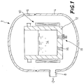
- FIG. 1 there is schematically shown a vacuum refining apparatus which is suitably used for effecting the vacuum refining method according to the present invention.
- reference numeral 2 denotes a vacuum container made of a suitable metallic material, which consists of a container body 4, and a removable lid member 6 for fluid-tightly closing an upper opening of the container body 4.
- the container body 4 is formed with a suction port 8 which is connected to a vacuum source such as a vacuum pump (not shown).
- a vacuum source such as a vacuum pump (not shown).
- an induction heater 10 in the form of a cylindrical coil made of a suitable material.
- This induction heater 10 is supplied through a power cable with an electric power having a predetermined frequency in a range of 10 - 100Hz, so as to effect induction heating as described later.
- a ladle 12 which is charged with a mass of molten metal 14 to be refined.
- An insulated segmented type ladle having a shell structure is used to practice the principle of the present invention.
- a mass of molten metal is refined in the following manner according to the present invention.
- the molten metal 14 to be refined is poured into the ladle 12.
- the molten metal 14 is produced by melting metal in a steel-making furnace such as an ordinary arc furnace or AOD furnace, or in a steel-making secondary smelting furnace.
- the lid member 6 of the vacuum container 2 is opened, and the ladle 12 is put into the vacuum container 2 such that the ladle 12 is located inside the diameter of the cylindrical coil of the induction heater 10 which is installed in place within the container 2.
- the lid member 6 is closed so as to maintain the vacuum container 2 in an air-tight condition. Then, the air in the container 2 is sucked through the suction port 8, by means of an external vacuum pump or other vacuum source.
- the degree of vacuum in the vacuum container 2 is appropriately selected within a range of about 13.3 - 1333.2 Pa (0.1 - 10 Torr). In some cases, however, the degree of vacuum in the container 2 is favorably controlled to be 13.3 Pa (0.1 Torr) or lower, in view of the properties of the molten steel to be refined.
- an electric power is supplied to the induction heater 10 so that the molten metal 14 in the ladle 12 is heated by induced electric current from the heater 10.
- the molten metal 14 is vacuum degassed by simultaneously evacuating and heating the metal 14.
- the molten metal 14 may be advantageously stirred by induced electric current generated by the induction heater 10.
- a suitable inert gas may be blown into the molten metal 14 as needed, through a porous plug 15 formed through the bottom wall of the ladle 12, so that the molten metal 14 is stirred by the inert gas.
- flux for making slag, and/or an alloy component(s) may be added to the molten metal 14 as needed, the temperature of the molten metal 14 is adjusted.
- the ladle 12 which contains the thus refined molten metal 14 is taken out of the vacuum container 2, and transferred to a desired location of casting where the molten metal 14 is tapped out of the ladle 12, through a sliding nozzle 16 formed through the bottom wall of the ladle 12.
- the ladle 12 which contains the molten metal 14 to be refined is accommodated in the vacuum container 2 which is held in a desired vacuum state. Therefore, the degree of vacuum of the atmosphere in the ladle 12 receiving the molten metal 14 may be easily controlled to a sufficiently high level. Further, since it takes a relatively short time to heat the molten metal 14 by the induction heater 10, it is possible to effectively reduce the refining time, while maintaining a sufficiently high level of degassing of the molten metal 14, such as deoxidation and dehydrogenation, until the melt 14 is tapped out of the ladle 12.
- the vacuum refining as described above may be combined with the conventional AOD method.
- a SUS steel for example, is refined first by the AOD method, and then by the instant vacuum refining method, the amount of Ar gas as a refining gas blown into the steel can be reduced, since the blowing of the Ar gas is required only during a reducing process following a decarbonizing or decarburizing process.
- a melt of 5 t of SUS304 was prepared by an AOD furnace, and the obtained steel melt was refined under vacuum by the vacuum refining apparatus as illustrated in Fig. 1.
- the ladle (12) receiving the molten steel (14) was set in position inside the cylindrical coil of the induction heater (10) installed in the vacuum container (2). Then, the container (2) was closed in a fluid-tight condition. Thereafter, the vacuum container (2) was evacuated by sucking the air in the container (2) through the suction port (8) by means of a vacuum pump. With the vacuum container (2) held under about 133.3 Pa (1.0 Torr) of vacuum, an electric power is supplied to the induction heater (10) so as to heat the molten steel (14) in the ladle (12) by induced electric current. At the same time, Ar gas was introduced into the molten steel (14) through the porous plug (15). In this manner, the molten steel (14) was refined for about 10 minutes.
- the lid member (6) of the vacuum container (2) was opened, and the ladle (12) was taken out of the container (2).
- the refined molten steel (14) in the ladle (12) was tapped at 1580°C into a casting mold, to produce two ingots each having 2.5 t. Thereafter, these ingots were hot-rolled into blooms, which were then rolled by a small rolling mill, so as to produce round steel bars having a diameter of 20mm.
- a melt of 5 t of SCM415 was prepared by an AF furnace, and the obtained steel melt was refined under vacuum by the vacuum refining apparatus as illustrated in Fig. 1.
- the molten steel (14) tapped out of the AF furnace at 1650°C was poured into the ladle (12), and was induction-heated under about 133.3 Pa (1 Torr) of vacuum within the vacuum container (2), in the same manner as in Example 1.
- flux such as CaO, CaF 2 and Al 2 O 3 was added by 5-25 kg per ton of the molten steel (14) while being heated.
- the molten metal (14) was refined for about 20 minutes.
- the vacuum container (2) was opened, and the ladle (12) was taken out of the container (2).
- the molten steel (14) was tapped out of the ladle (12) at 1640°C, and was cast into two ingots similar to those obtained in Example 1. These ingots were then hot-rolled into blooms, which were then rolled by a small rolling mill, so as to produce round steel bars having a diameter of 20mm.
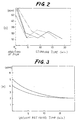
- a mass of molten steel (SUS403) was heated under vacuum in the vacuum refining apparatus as shown in Fig. 1.
- the vacuum refining of the steel was effected at 1550°C under 666.6 Pa (5 Torr) of vacuum, with the molten steel stirred by bubbling of Ar gas as well as by induced electric current generated by the induction heater (10).
- the graph of Fig. 3 indicates the hydrogen concentration in the molten steel with respect to the vacuum refining time.
Landscapes
- Chemical & Material Sciences (AREA)
- Engineering & Computer Science (AREA)
- Materials Engineering (AREA)
- Metallurgy (AREA)
- Organic Chemistry (AREA)
- Manufacturing & Machinery (AREA)
- Mechanical Engineering (AREA)
- Treatment Of Steel In Its Molten State (AREA)
- Furnace Details (AREA)
- Manufacture And Refinement Of Metals (AREA)
Claims (7)
- Unterdruckfrischgerät zum Frischen einer Masse einer Metallschmelze, die aus einem Stahlherstellungsofen oder einem Stahlherstellungsnachschmelzofen erhalten wird, mit- einer Pfanne (12) zum Aufnehmen der Masse der Metallschmelze (14);- einer Induktionsheizung (10) zum Heizen der Metallschmelze in der Pfanne durch einen elektrischen Induktionsstrom;- einem geschlossenen Behälter (2) zum Unterbringen der Induktionsheizung und der Pfanne darin; und- einer Vakuumherstelleinrichtung zum Herstellen eines Unterdrucks in dem geschlossenen Behälter,dadurch gekennzeichnet, daß
die Pfanne (12) einen Mantelaufbau hat, der elektrisch voneinander isolierte Segmente und einen durch eine Bodenwand der Pfanne gebildeten porösen Pfropfen (15) umfaßt, durch den ein Inertgas in die Metallschmelze geblasen wird, wobei die Pfanne relativ zu der um die Pfanne herum angeordneten und in dem geschlossenen Behälter (2) befestigten Induktionsheizung (10) bewegbar ist, und wobei die Unterdruckherstelleinrichtung eine Einrichtung zum Herstellen eines Unterdrucks in dem geschlossenen Behälter auf ein Unterdruckausmaß unter 1333,2 Pa (10 Torr) ist. - Unterdruckfrischgerät nach Anspruch 1, wobei die Induktionsheizung (10) eine zylindrische Spule aufweist, die mit einem elektrischen Strom zum Erzeugen des elektrischen Induktionsstroms versorgt wird.
- Unterdruckfrischgerät nach Anspruch 1 oder 2, wobei der geschlossene Behälter (2) aus einem Behälterkörper (4) mit einer Öffnung und einem Deckelelement (6) zum fluiddichten Verschließen der Öffnung des Behälterkörpers besteht, wobei der Behälterkörper eine Saugöffnung (8) hat, durch die die Luft in dem geschlossenen Behälter durch die Unterdruckherstelleinrichtung abgesaugt wird.
- Unterdruckfrischverfahren zum Frischen einer Masse einer Metallschmelze, die aus einem Stahlherstellungsofen oder einem Stahlherstellungsnachschmelzofen erhalten wird, mit den folgenden Schritten:- Gießen der Metallschmelze (14) in eine Pfanne (12), die elektrisch voneinander isolierte Segmente umfaßt;- Einführen der mit der Metallschmelze gefüllten Pfanne in einen geschlossenen Behälter (2), so daß die Pfanne im Inneren einer in dem geschlossenen Behälter (2) befestigten Induktionsheizung (10) angeordnet ist;- Herstellen eines Vakuums in dem geschlossenen Behälter auf ein Unterdruckausmaß unter 1333,2 Pa (10 Torr);- Induktionsheizen der Metallschmelze in der Pfanne durch die Induktionsheizung während der geschlossene Behälter unter einem Unterdruck gehalten wird, um so die Metallschmelze zu frischen, und Umrühren der Metallschmelze durch ein Inertgas, das in die Metallschmelze durch eine Bodenwand der Pfanne geblasen wird; und- Herausnehmen der Pfanne aus dem geschlossenen Behälter, wobei die Induktionsheizung in dem geschlossenen Behälter verbleibt.
- Unterdruckfrischverfahren nach Anspruch 4, das desweiteren den Schritt des Umrührens der Metallschmelze in der Pfanne durch einen Induktionsstrom aufweist, der durch die Induktionsheizung (10) erzeugt wird.
- Unterdruckfrischverfahren nach Anspruch 4 oder 5, das desweiteren den Schritt des Hinzufügens eines Flußmittels zum Erzeugen einer Schlacke zu der Metallschmelze aufweist.
- Unterdruckfrischverfahren nach einem der Ansprüche 4 bis 6, das desweiteren den Schritt des Hinzufügens einer Legierungskomponente zu der Metallschmelze aufweist.
Applications Claiming Priority (2)
| Application Number | Priority Date | Filing Date | Title |
|---|---|---|---|
| JP339101/90 | 1990-11-30 | ||
| JP2339101A JPH04202710A (ja) | 1990-11-30 | 1990-11-30 | 真空精錬方法 |
Publications (2)
| Publication Number | Publication Date |
|---|---|
| EP0488293A1 EP0488293A1 (de) | 1992-06-03 |
| EP0488293B1 true EP0488293B1 (de) | 1997-03-26 |
Family
ID=18324270
Family Applications (1)
| Application Number | Title | Priority Date | Filing Date |
|---|---|---|---|
| EP91120407A Expired - Lifetime EP0488293B1 (de) | 1990-11-30 | 1991-11-28 | Verfahren zur Pfannenstandentgasung mit einer die Pfanne umgebenden Induktionszusatzheizung |
Country Status (5)
| Country | Link |
|---|---|
| US (1) | US5160531A (de) |
| EP (1) | EP0488293B1 (de) |
| JP (1) | JPH04202710A (de) |
| AT (1) | ATE150798T1 (de) |
| DE (1) | DE69125347T2 (de) |
Families Citing this family (4)
| Publication number | Priority date | Publication date | Assignee | Title |
|---|---|---|---|---|
| DE4328045C2 (de) * | 1993-08-20 | 2001-02-08 | Ald Vacuum Techn Ag | Verfahren zum Entkohlen von kohlenstoffhaltigen Metallschmelzen |
| US5851262A (en) * | 1994-11-25 | 1998-12-22 | Hitachi Metals, Ltd. | Method of refining molten metal |
| KR100920172B1 (ko) * | 2009-03-03 | 2009-10-06 | 대교엔지니어링(주) | 진공 탈가스 장치 및 이를 이용한 진공 탈가스 방법 |
| CN111172355A (zh) * | 2020-01-10 | 2020-05-19 | 中冶赛迪工程技术股份有限公司 | 一种感应加热单嘴真空精炼炉及洁净钢冶炼工艺 |
Family Cites Families (9)
| Publication number | Priority date | Publication date | Assignee | Title |
|---|---|---|---|---|
| GB912924A (en) * | 1958-06-16 | 1962-12-12 | Heraeus Gmbh W C | Improvements in or relating to the vacuum-degasification of molten metals |
| US3185565A (en) * | 1962-11-16 | 1965-05-25 | Pennsalt Chemicals Corp | Method and apparatus for safe operation of vacuum chambers |
| SE311533B (de) * | 1963-11-11 | 1969-06-16 | Asea Ab | |
| FR1475783A (fr) * | 1966-02-04 | 1967-04-07 | Est Aciers Fins | Installation pour l'élaboration et la coulée continue de l'acier |
| US4743302A (en) * | 1986-06-06 | 1988-05-10 | Vlsi Packaging Materials, Inc. | Low melting glass composition |
| US4780134A (en) * | 1986-09-23 | 1988-10-25 | A. Finkl & Sons Co. | Simplified method and apparatus for treating molten steel |
| US4762554A (en) * | 1986-11-10 | 1988-08-09 | Lazcano Navarro Arturo | Process to eliminate hazardous components from the electric arc furnace flue dust and recovering of metals |
| US4945071A (en) * | 1989-04-19 | 1990-07-31 | National Starch And Chemical Investment Holding Company | Low softening point metallic oxide glasses suitable for use in electronic applications |
| US5013697A (en) * | 1990-06-21 | 1991-05-07 | Johnson Matthey Inc. | Sealing glass compositions |
-
1990
- 1990-11-30 JP JP2339101A patent/JPH04202710A/ja active Pending
-
1991
- 1991-11-21 US US07/795,837 patent/US5160531A/en not_active Expired - Fee Related
- 1991-11-28 EP EP91120407A patent/EP0488293B1/de not_active Expired - Lifetime
- 1991-11-28 AT AT91120407T patent/ATE150798T1/de not_active IP Right Cessation
- 1991-11-28 DE DE69125347T patent/DE69125347T2/de not_active Expired - Fee Related
Also Published As
| Publication number | Publication date |
|---|---|
| DE69125347T2 (de) | 1997-09-04 |
| ATE150798T1 (de) | 1997-04-15 |
| EP0488293A1 (de) | 1992-06-03 |
| US5160531A (en) | 1992-11-03 |
| JPH04202710A (ja) | 1992-07-23 |
| DE69125347D1 (de) | 1997-04-30 |
Similar Documents
| Publication | Publication Date | Title |
|---|---|---|
| US6238453B1 (en) | Producing stainless steels in parallel operated vessels | |
| EP0752478B1 (de) | Verfahren zum raffinieren von metall | |
| US3501290A (en) | Method of treating molten metal with arc heat and vacuum | |
| US4462878A (en) | Method of treating and refining liquid metal alloys by direct current electric arc heating | |
| EP0725151A1 (de) | Verfahren und vorrichtung zum feinen von metallschmelzen | |
| US5160531A (en) | Vaccum refining method utilizing induction heater around a ladle in a vacuum container | |
| US4027095A (en) | Hermetically sealed arc furnace | |
| US4154602A (en) | Method of denitriding a high chromium molten steel with a minimum chromium loss | |
| GB2281312A (en) | Process for decarburizing carbon-containing molten metal | |
| US3961779A (en) | Apparatus and method for refining a metal melt | |
| CN114921611A (zh) | 一种生产大型优质合金结构钢和优质碳素结构钢钢锭的工艺方法 | |
| KR100399220B1 (ko) | 전기강판제조용용강정련방법 | |
| JPS5887234A (ja) | 真空溶解精錬法 | |
| JPH04318118A (ja) | 極低炭・極低硫鋼の製造方法 | |
| JP2983327B2 (ja) | 真空精錬装置 | |
| KR102925195B1 (ko) | 강괴의 제조방법 | |
| SU506186A1 (ru) | Способ выплавки нержавеющих сталей | |
| US4655826A (en) | Method for post-melting treatment of molten steel | |
| JPS6318645B2 (de) | ||
| KR920004700B1 (ko) | 레이들 정련법 및 장치 | |
| JP4132918B2 (ja) | 低炭素フェロボロンの製造方法 | |
| Kumar et al. | Reducing Al consumption in steelmaking | |
| JPH05337607A (ja) | 取鍋収容容器 | |
| JP3684445B2 (ja) | 高純度高Ni鋼の製造方法 | |
| JP3465801B2 (ja) | Fe−Ni系合金溶湯の精錬方法 |
Legal Events
| Date | Code | Title | Description |
|---|---|---|---|
| PUAI | Public reference made under article 153(3) epc to a published international application that has entered the european phase |
Free format text: ORIGINAL CODE: 0009012 |
|
| AK | Designated contracting states |
Kind code of ref document: A1 Designated state(s): AT DE FR GB IT SE |
|
| 17P | Request for examination filed |
Effective date: 19921009 |
|
| 17Q | First examination report despatched |
Effective date: 19921113 |
|
| GRAG | Despatch of communication of intention to grant |
Free format text: ORIGINAL CODE: EPIDOS AGRA |
|
| GRAH | Despatch of communication of intention to grant a patent |
Free format text: ORIGINAL CODE: EPIDOS IGRA |
|
| GRAH | Despatch of communication of intention to grant a patent |
Free format text: ORIGINAL CODE: EPIDOS IGRA |
|
| GRAA | (expected) grant |
Free format text: ORIGINAL CODE: 0009210 |
|
| AK | Designated contracting states |
Kind code of ref document: B1 Designated state(s): AT DE FR GB IT SE |
|
| REF | Corresponds to: |
Ref document number: 150798 Country of ref document: AT Date of ref document: 19970415 Kind code of ref document: T |
|
| REF | Corresponds to: |
Ref document number: 69125347 Country of ref document: DE Date of ref document: 19970430 |
|
| ET | Fr: translation filed | ||
| PLBE | No opposition filed within time limit |
Free format text: ORIGINAL CODE: 0009261 |
|
| STAA | Information on the status of an ep patent application or granted ep patent |
Free format text: STATUS: NO OPPOSITION FILED WITHIN TIME LIMIT |
|
| 26N | No opposition filed | ||
| PGFP | Annual fee paid to national office [announced via postgrant information from national office to epo] |
Ref country code: SE Payment date: 19981105 Year of fee payment: 8 |
|
| PGFP | Annual fee paid to national office [announced via postgrant information from national office to epo] |
Ref country code: FR Payment date: 19981110 Year of fee payment: 8 |
|
| PGFP | Annual fee paid to national office [announced via postgrant information from national office to epo] |
Ref country code: GB Payment date: 19981204 Year of fee payment: 8 |
|
| PGFP | Annual fee paid to national office [announced via postgrant information from national office to epo] |
Ref country code: AT Payment date: 19991112 Year of fee payment: 9 |
|
| PG25 | Lapsed in a contracting state [announced via postgrant information from national office to epo] |
Ref country code: GB Free format text: LAPSE BECAUSE OF NON-PAYMENT OF DUE FEES Effective date: 19991128 |
|
| PG25 | Lapsed in a contracting state [announced via postgrant information from national office to epo] |
Ref country code: SE Free format text: LAPSE BECAUSE OF NON-PAYMENT OF DUE FEES Effective date: 19991129 |
|
| PGFP | Annual fee paid to national office [announced via postgrant information from national office to epo] |
Ref country code: DE Payment date: 19991129 Year of fee payment: 9 |
|
| EUG | Se: european patent has lapsed |
Ref document number: 91120407.1 |
|
| GBPC | Gb: european patent ceased through non-payment of renewal fee |
Effective date: 19991128 |
|
| PG25 | Lapsed in a contracting state [announced via postgrant information from national office to epo] |
Ref country code: FR Free format text: LAPSE BECAUSE OF NON-PAYMENT OF DUE FEES Effective date: 20000731 |
|
| REG | Reference to a national code |
Ref country code: FR Ref legal event code: ST |
|
| PG25 | Lapsed in a contracting state [announced via postgrant information from national office to epo] |
Ref country code: AT Free format text: LAPSE BECAUSE OF NON-PAYMENT OF DUE FEES Effective date: 20001128 |
|
| PG25 | Lapsed in a contracting state [announced via postgrant information from national office to epo] |
Ref country code: DE Free format text: LAPSE BECAUSE OF NON-PAYMENT OF DUE FEES Effective date: 20010801 |
|
| PG25 | Lapsed in a contracting state [announced via postgrant information from national office to epo] |
Ref country code: IT Free format text: LAPSE BECAUSE OF NON-PAYMENT OF DUE FEES;WARNING: LAPSES OF ITALIAN PATENTS WITH EFFECTIVE DATE BEFORE 2007 MAY HAVE OCCURRED AT ANY TIME BEFORE 2007. THE CORRECT EFFECTIVE DATE MAY BE DIFFERENT FROM THE ONE RECORDED. Effective date: 20051128 |