EP0488292A2 - Système de mesure de valeurs de forme tridimensionelle - Google Patents
Système de mesure de valeurs de forme tridimensionelle Download PDFInfo
- Publication number
- EP0488292A2 EP0488292A2 EP91120406A EP91120406A EP0488292A2 EP 0488292 A2 EP0488292 A2 EP 0488292A2 EP 91120406 A EP91120406 A EP 91120406A EP 91120406 A EP91120406 A EP 91120406A EP 0488292 A2 EP0488292 A2 EP 0488292A2
- Authority
- EP
- European Patent Office
- Prior art keywords
- light
- slit
- image
- scattered
- detecting
- Prior art date
- Legal status (The legal status is an assumption and is not a legal conclusion. Google has not performed a legal analysis and makes no representation as to the accuracy of the status listed.)
- Withdrawn
Links
Images


Classifications
-
- G—PHYSICS
- G01—MEASURING; TESTING
- G01B—MEASURING LENGTH, THICKNESS OR SIMILAR LINEAR DIMENSIONS; MEASURING ANGLES; MEASURING AREAS; MEASURING IRREGULARITIES OF SURFACES OR CONTOURS
- G01B11/00—Measuring arrangements characterised by the use of optical techniques
- G01B11/24—Measuring arrangements characterised by the use of optical techniques for measuring contours or curvatures
- G01B11/25—Measuring arrangements characterised by the use of optical techniques for measuring contours or curvatures by projecting a pattern, e.g. one or more lines, moiré fringes on the object
- G01B11/2518—Projection by scanning of the object
- G01B11/2522—Projection by scanning of the object the position of the object changing and being recorded
-
- G—PHYSICS
- G01—MEASURING; TESTING
- G01B—MEASURING LENGTH, THICKNESS OR SIMILAR LINEAR DIMENSIONS; MEASURING ANGLES; MEASURING AREAS; MEASURING IRREGULARITIES OF SURFACES OR CONTOURS
- G01B11/00—Measuring arrangements characterised by the use of optical techniques
- G01B11/24—Measuring arrangements characterised by the use of optical techniques for measuring contours or curvatures
- G01B11/25—Measuring arrangements characterised by the use of optical techniques for measuring contours or curvatures by projecting a pattern, e.g. one or more lines, moiré fringes on the object
- G01B11/2518—Projection by scanning of the object
Definitions
- This invention relates to a non-contacting three-dimensional shape data reading system for reading data representing a three-dimensional shape of a material object without contacting the object and to a three-dimensional image data input system for reading image data on a region of an object having a two-dimensional spread.
- a conventional three-dimensional measuring instrument for measuring a micro-height of an object, which is provided with an XY table and a contacting element for measuring the height (namely, the dimension in Z-direction) of the object.
- the dimension in each of X-, Y- and Z-directions of the object is measured or read, putting the object on the XY table and bringing the contacting element into contact with the object.
- Such a three-dimensional measuring instrument has drawbacks in that it is very time-consuming to measure or obtain three dimensional data on a region having a spread and in that there is a limit to a pitch in X- and Y-directions due to the size of the contacting element.
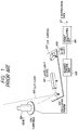
- reference numeral 601 designates a laser light source for emitting laser beams (hereunder sometimes referred to as spot-laser-light); 602 an oscillation mirror for converting the spot-laser-light into what is called slit-light which is equivalent to light emitted from a slit; 603 the slit-light; 604 an object to be measured; 606 a turntable for rotating the object put thereon; 607 a charge-coupled-device (CCD) camera; 608 an analog-to-digital (A/D) converter for converting an output signal of the CCD camera 607 into a digital signal; 609 a scanner control unit for controlling the entire system; 610 a height calculating unit for calculating the height of the object from an image formed by the slit-light 603, namely, scattered light; and 611 a signal representing three-dimensional data
- the spot-laser light emitted from the laser source 601 is converted by the oscillation mirror 602 into the slit-light 603 which is irradiated on the object 604. Furthermore, the object 604 put on the turntable 606 rotates together with the turntable, receiving the slit-light 603.
- the CCD camera 607 picks up, namely, receives the scattered slit-light corresponding to each scene of the object, which is rotating, in synchronization with the rotation of the object. In this case, as the result of taking a picture of a scene by using the CCD camera 607, unevennesses corresponding to ruggednesses of the surface of the object 604 are shown in an image formed by the scattered slit-light.
- the A/D converter 608 converts a signal outputted from the CCD camera 607 to a digital signal and further transmits the digital signal to the height calculating unit 610. Then, in the height calculating unit 610, the digital picture signal is stored in a memory thereof. Further, in each vertical scanning direction, a point Q (u q , w q ), at which the luminance has a maximum value, is found and an image of a point to be measured (hereunder referred to simply as a measuring point) is considered as formed at the found point.
- the coordinates of the measuring point Q are calculated as follows. For simplicity of calculation, it is assumed that the CCD camera 607 is set and the slit-light is propagated in an orthogonal coordinates system as illustrated in FIG. 2.
- a point of intersection of the slit-light 603 and the CCD camera 607 is set to be an origin 0(0,0,0).
- an XZ-plane is placed in such a manner to meet at right angle with the slit-light 603.
- the direction, in which the slit-light 603 advances, is included in a YZ-plane, and the CCD camera 607 is mounted on the XZ-plane.
- P(x p , y p , z p ), B(l, 0, z o ), A(0, 0, z o ) and Q(u q , w q ) denote the coordinates of a measuring point P, the coordinates of the position of the CCD camera 607, the coordinates of a point A of intersection of the perpendicular from the position of the CCD camera 607 and the YZ-plane and the coordinates of the position Q of an image of the measuring point P formed on the light receiving plane of the CCD camera 607, respectively.
- the following equations (1) holds and the coordinates of the measuring point P can be obtained therefrom.
- three-dimensional data regarding a surface of the object, on which the laser slit-light is irradiated can be obtained. Further, three-dimensional data on the entire object can be obtained by finding three-dimensional data corresponding to each angle of rotation of the object by rotating the object together with the turntable.
- Such a conventional instrument cannot receive slit-light scattered from a surface, on which the slit-light is not irradiated, or another surface, which is not seen from the CCD camera, of the object.
- the present invention is created to eliminate such a defect of the conventional instrument.
- an object of the present invention to a three-dimensional image data input system which can obtain higher quality three-dimensional data by eliminating a surface, on which slit-light is not irradiated, and another surface, which is not seen from the CCD camera, of an object to be measured.
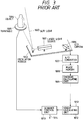
- FIG. 3 is a diagram for showing the construction of this conventional non-contacting three-dimensional shape data reading system.
- reference numeral 1001 designates a laser light source for generating a laser beam or spot-laser-light; 1002 an oscillation mirror for converting spot-laser-light into slit-light; 1003 the slit-light; 1004 an object to be measured; 1005 a turntable for rotating the object put thereon; 1006 a CCD camera for reading light (hereunder sometimes referred to simply as scattered light) obtained by scattering the slit-light 1003; 1007 an A/D converter for converting an output signal of the CCD camera 1006 into a digital signal; 1008 an image memory for storing an image signal; 1009 a centroid calculating unit for calculating the centroid of a picture formed by the scattered slit-light from the object (namely, calculating the "center of gravity" in case of regarding the luminance at each point of the picture as the "mass" thereof); 1012 a height calculating
- the spot-laser-light emitted from the laser light source 1001 is transformed by the oscillation mirror 1002 into the slit-light 1003 which is then irradiated on the object 1004.
- the object 1004 rotates around the axis of rotation of the turntable 1005, receiving the slit-light.
- the CCD camera 1006 receives the scattered slit-light corresponding to each scene of the object, which is rotating, in synchronization with the rotation of the object.
- the centroid calculating unit 1009 finds the centroid of the picture, which is represented by the image signal and is formed by the slit-light scattered from the object, in each vertical scanning direction by regarding the luminance at each point of the picture as the "mass" thereof.
- the height calculating unit 1012 calculates three-dimensional coordinates of the measuring point according to principles of trigonometry by using the length of the ground line or vase line (namely, the distance between the slit-light and the CCD camera), the sectional angle (namely, the angle determined by the slight-light and the optical axis of the CCD camera) and an angle determined by the optical axis of the CCD camera and a segment drawn from the position of the CCD camera to the measuring point by regarding the centroid as the measuring point.
- three-dimensional shape data representing the shape of the object are obtained correspondingly to the slit-light.
- three-dimensional shape data on the entire object can be obtained by controlling and synchronizing a rotation of the turntable and the calculation by means of the scanner control unit 1013.
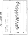
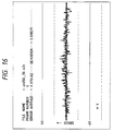
- this conventional three-dimensional shape data reading system performs a centeroid-calculating operation on sampled data represented by the image signal and calculates the coordinates of the measuring point by regarding the centroid as the center of the image formed by the scattered slit-light.
- the three-dimensional data include periodic errors as shown in FIG. 4.
- This conventional three-dimensional shape data reading system has encountered a problem of how to reduce such errors.
- the present invention is accomplished to solve such a problem of the prior art.
- a three-dimensional image data input system which comprises a slit-light source for generating slit-light, a turntable for rotating an object to be measured, a top reflection mirror provided over the object in such a manner to meet at right angles with a beam of the slit-light, a camera for taking an image formed by the scattered slit-light from the object and another image formed by light obtained by reflecting the scattered slit-light on the same pickup plane and a distance calculating unit for calculating a distance between a measuring point of the object and an origin on the basis of an electric signal outputted from the camera indicating a position of an image, which is formed by the slit-light scattered from the object, of the measuring point of the object and another electric signal outputted from the camera indicating a position of another image, which is formed by light obtained by reflecting the slit-light scattered from the object by the top reflection mirror.
- a three-dimensional image data input system which comprises a slit-light source for generating slit-light, a moving mechanism for moving an object to be measured, a top reflection mirror provided over the object in such a manner to meet at right angles with a beam of the slit-light, a camera for taking an image formed by the scattered slit-light from the object and another image formed by light obtained by reflecting the scattered slit-light on the same pickup plane and a distance calculating unit for calculating a distance between a measuring point of the object and an origin on the basis of an electric signal outputted from the camera indicating a position of an image, which is formed by the slit-light scattered from the object, of the measuring point of the object and another electric signal outputted from the camera indicating a position of another image, which is formed by light obtained by reflecting the slit-light scattered from the object by the top reflection mirror.
- three-dimensional data on top and side surfaces of the object corresponding to a beam of the slit-light can be obtained. Because these two pieces of the three-dimensional data are complemented with each other, high-precision three-dimensional data can be obtained by synthsizing these data. Consequently, good-quality three-dimensional data can be obtained by eliminating a surface, on which the slit-light is not irradiated, and another surface, which is not seen from the CCD camera, of the object.
- a three-dimensional shape data reading system which comprises a slit-light source for generating slit-light, a moving mechanism for moving an object to be measured, a camera for taking an image formed by scattered slit-light from the object, an A/D converter for converting a luminance signal into a digital image signal, an image memory for storing the image signal, a centeroid detecting unit for detecting the centroid of a picture formed by the slit-light scattered by the object from the image signal stored in the image memory, phase shift amount detecting unit for detecting a phase shift amount between the center of the picture formed by the scattered slit-light and a sampling pitch, a center detecting unit for detecting the center of the picture by correcting the centroid from the phase shift amount and a height calculating unit for calculating three-dimensional coordinates of a measuring point of the object from the detected center.
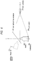
- a three-dimensional image data input system of the present invention is characterized by comprising a top reflection mirror, which meets at right angles with as beam of slit-light and is provided over an object to be measured, in addition to the composing elements of tee conventional three-dimensional image data input system.
- reference numeral 203 represents slit-light
- 204 a top reflection mirror
- 205 an objected to be measured
- 206 a turntable
- 207 a CCD camera.
- FIG. 7 illustrates how the CCD camera of FIG. 6 takes a picture of the object.
- reference numeral 305 denotes a real image of the object; 307 a pickup plane (namely, a taking plane) of the CCD camera; 312 a virtual image of the object; 313 a real image formed by scattered slit-light; and 314 a virtual image formed by the scattered slit-light.
- FIG. 8(b) illustrates an example of three-dimensional data regarding a side surface of the object, which are obtained correspondingly to a beam of the slit-light.
- FIG. 8(a) illustrates an example of three-dimensional data regarding a top surface of the object, which are obtained correspondingly to a beam of the slit-light.
- FIG. 6 shows a view taken from the positive direction along X-axis.
- an image 305 of the object and a real image 313, which is formed by the scattered slit-light are formed on a lower half of the pickup plane of the CCD camera 207 and a virtual image 312 of the object and a virtual image, which is formed by the scattered slit-light, are formed on an upper half of the pickup plane thereof as illustrated in FIG. 7.
- a point having maxium luminance in each vertical scanning direction is detected from the images formed on the lower half. Then three-dimensional image data regarding a side surface of the object can be obtained by regarding the detected point as an image of a measuring point of the object and calculating the equation (1). Similarly, a point having maxium luminance in each vertical scanning direction is detected from the images formed on the upper half. Then three-dimensional image data regarding a virtual image of a top surface of the object can be obtained by regarding the detected point as a virtual image of a measuring point of the object and calculating the equation (1).
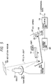
- reference numeral 101 a laser light source for generating spot-laser-light; 102 an oscillation mirror for converting the spot-laser-light to slit-light; 103 the slit-light; 104 an object to be measured; 105 a top reflection mirror provided over the object 104; 106 a turntable for rotating the object 104; 107 a CCD camera for reading or receiving light obtained by scattering the slit-light or by reflecting the scatterd slit-light by the top reflection mirror; 108 an A/D converter for converting an output signal of the CCD camera 107 into a digital signal; 109 a scanner control unit for controlling the entire system; 110 a height calculating unit for calculating the height of the object from the digital signal; and 111 a signal representing three-dimensional data obtained by this system.
- the spot-laser-light from the source 101 is converted by the oscillation mirror 102 into the slit-light 103. Further, the slit-light is irradiated on the side surface of the object 104. Moreover, light obtained by reflecting the slit-light 103 by means of the top reflection mirror 105 is irradiated on the top surface of the object 104.
- the top reflection mirror 105 is provided orthogonally to a beam of the slit-light 103 in such a manner that a beam of the slit-light 103 and a beam obtained by reflecting the beam of the slit-light by use of the top reflection mirror 105 are on the same plane.
- the CCD camera 107 forms the real image of the object and that formed by the scattered slit-light on the lower half of the pickup plane thereof and also forms the virtual image of the object 104 and that formed from the light obtained by reflecting the slit-light by means of the top reflection mirror on the upper half of the pickup plane thereof.
- Luminance data are transmitted through the A/D converter 108 to the height calculating unit 110.
- the scanner control unit 109 controls the entire system in such a manner to synchronize the rotation of the turntable, the reading operation of the CCD camera 107 and the height calculating operation of the height calculating unit 110 with one another.
- the height calculating unit 110 is comprised of a microcomputer, a memory and an input/output (I/O) interface and obtains three-dimensional image data by performing the following procedure by executing software. Namely, digital luminance data corresponding to the slit-light at the time of turning the object an angle of ⁇ from the reference coordinate are inputted to the memory thereof through the I/O interface. As illustrated in FIG. 7, data regarding the virtual image 312 of the object and that 314 formed by the scattered slit-light are stored in an upper half of a corresponding storage region of the memory. Further, a point Q(u q , w q ) having maximum luminance in each vertical scanning direction is detected from the images formed on the lower half.
- the first embodiment can obtain good-quality three-dimensional image data.
- reference numeral 701 a laser light source for generating spot-laser-light; 702 an oscillation mirror for converting the spot-laser-light to slit-light; 703 the slit-light; 704 an object to be measured; 705 a top reflection mirror provided over the object 704; 706 a general purpose single axis carrier for moving the object 704; 707 a CCD camera for reading or receiving light obtained by scattering the slit-light 703 or by reflecting the scattered slit-light by the top reflection mirror; 708 an A/D converter for converting an output signal of the CCD camera 707 into a digital signal; 709 a scanner control unit for controlling the entire system; 710 a height calculating unit for calculating the height of the object from the digital signal; and 711 a signal representing three-dimensional data obtained by this system.
- the spot-laser-light from the source 701 is converted by the oscillation mirror 702 into the slit-light 703. Further, the slit-light is irradiated on the side surface of the object 704. Moreover, light obtained by reflecting the slit-light 703 by means of the top reflection mirror 705 is irradiated on the top surface of the object 704.
- the top reflection mirror 705 is provided orthogonally to a beam of the slit-light 703 in such a manner that a beam of the slit-light 703 and a beam obtained by reflecting the beam of the slit-light by use of the top reflection mirror 105 are on the same plane.
- the CCD camera 707 forms the real image of the object and that formed by the scattered slit-light on the lower half of the pickup plane thereof and also forms the virtual image of the object 704 and that formed from the light obtained by reflecting the slit-light by means of the top reflection mirror on the upper half of the pickup plane thereof.
- Luminance data are transmitted through the A/D converter 708 to the height calculating unit 710.
- the scanner control unit 709 controls the entire system in such a manner to synchronize the movement of the single axis carrier, the reading operation of the CCD camera 707 and the height calculating operation of the height calculating unit 710 with one another.
- the height calculating unit 710 is comprised of a microcomputer, a memory and an input/output (I/O) interface and obtains three-dimensional image data by performing the following procedure by executing software. Namely, digital luminance data corresponding to the slit-light at the time of moving the object by a distance d from the reference coordinate are inputted to the memory thereof through the I/O interface. As illustrated in FIG. 7, data regarding the virtual image 312 of the object and that 314 formed by the scattered slit-light are stored in an upper half of a corresponding storage region of the memory. Further, a point Q(u q , w q ) having maximum luminance in each vertical scanning direction is detected from the images formed on the lower half.
- the second embodiment can also obtain good-quality three-dimensional image data.
- FIGS. 10 to 16 Next, a third embodiment of the present invention will be described in detail hereinbelow by referring to FIGS. 10 to 16.
- the third embodiment utilizes the property of a periodic error.
- the property of the periodic error can be analyzed by the following experiment. Namely, assuming that the intensity of slit-light has a normal distribution, the relation between a phase shift amount from the median of the normal distribution to a sampling pitch and an error from the centroid of sampled shape data to the median of the normal distribution as illustrated in FIG. 11 is obtained as the result of a computer simulation.
- FIG. 11 shows the result of the simulation in case of sampling a shaded portion of the normal distribution of FIG. 12.
- the phase shift amount means an amount of shift of the shaded portion from the median of the normal distribution. As is seen from FIG. 11, the larger the phase shift amount from the median of the normal distribution to a sampling pitch becomes, the larger the error becomes.
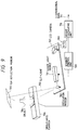
- FIG. 10 is a diagram for showing the construction of the third embodiment (namely, a three-dimensional shape data reading system embodying the present invention).
- reference numeral 801 designates a laser light source for generating a laser beam or spot-laser-light; 802 an oscillation mirror for converting spot-laser-light into slit-light; 803 the slit-light; 804 an object to be measured; 805 a turntable for rotating the object put thereon; 806 a CCD camera for reading scattered light obtained by scattering the slit-light 803; 807 an A/D converter for converting an output signal of the CCD camera 806 into a digital signal; 808 an image memory for storing an image signal; 809 a centroid calculating unit for calculating the centroid of a picture formed by the slit-light scattered from the object and represented by the image signal; 810 a phase shift amount detecting unit for detecting a phase shift amount between the center of the picture formed by the scattered slit-light and a
- the spot-laser-light emitted from the laser light source 801 is transformed by the oscillation mirror 802 into the slit-light 803 which is then irradiated on the object 804.
- the object 804 rotates around the axis of rotation of the turntable 805, receiving the slit-light 803.
- the CCD camera 806 receives the scattered slit-light corresponding to each scene of the object, which is rotating, in synchronization with the rotation of the object.
- the centroid calculating unit 809 finds the centroid u q of the picture, which is represented by the image signal and is formed by the slit-light scattered from the object, in each vertical scanning line w q by regarding the luminance at each point of the picture as the "mass" thereof.
- the center of the picture by correcting the centroid from the phase shift amount is detected by performing the following method. Namely, in each vertical scanning line to be measured, a point (hereunder sometimes referred to as a maximum point) having maximum luminance and points respectively placed at both sides of the maximum point are detected. Further, let d i , d i-1 and d i+1 designate the luminance of the maximum point and those of the points respectively placed at both sides of the maximum point.
- This error function y is a hyperbolic function as illustrated in FIG. 15.
- k represents a parameter for controlling a maximal point and a minimal point; and
- c a parameter for controlling a maximal value and a minimal value.
- These parameters k and c are pre-set in this system before the calculation of the center.
- FIG. 16 is a graph showing three-dimensional shape data obtained by the third embodiment, which are measured under the same condition as in case of FIG. 4. As is apparent from comparison of FIG. 16 with FIG. 4, a periodic error as shown in FIG. 4 is eliminated in case of FIG. 16.
- the third embodiment obtains higher-precision three-dimensional shape data.
- the centroid detecting unit, the phase shift amount unit, the center detecting unit and the height calculating unit are implemented by executing software in a microcomputer. These units, however, may be implemented by using hardware technique based on recent digital circuit techniques (or using firmware). Further, in the phase shift amount unit, any other equations having the same functions as the equations (4) and (5) have may be employed. Moreover, in the center detecting unit, any other equations having the same function as the equation (6) has may be employed.
- a correction amount for correcting the centeroid may be preliminarily calculated regarding the phase shift amount and stored in the memory and thereafter, when calculating the center, the preliminarily stored correction amount may be referred by employing, for instance, what is called a table lookup method.
- a three-dimensional shape data reading system provided with a slit-light source for generating slit-light, a moving mechanism for moving an object to be measured, a camera for taking an image formed by scattered slit-light from the object, an analog-to-digital converter for converting a luminance signal into a digital image signal, an image memory for storing the image signal, a centeroid detecting unit for detecting the centroid of a picture formed by the slit-light scattered by the object from the image signal stored in the image memory, phase shift amount detecting unit for detecting a phase shift amount between the center of the picture formed by the scattered slit-light and a sampling pitch, a center detecting unit for detecting the center of the picture by correcting the centroid from the phase shift amount and a height calculating unit for calculating three-dimensional coordinates of the object from the detected center.
- a slit-light source for generating slit-light
- a camera for taking an image formed by scattered slit-light from the object
Landscapes
- Engineering & Computer Science (AREA)
- Computer Vision & Pattern Recognition (AREA)
- Physics & Mathematics (AREA)
- General Physics & Mathematics (AREA)
- Length Measuring Devices By Optical Means (AREA)
Applications Claiming Priority (4)
| Application Number | Priority Date | Filing Date | Title |
|---|---|---|---|
| JP2334008A JPH04127006A (ja) | 1990-06-20 | 1990-11-29 | 三次元画像入力装置 |
| JP334008/90 | 1990-11-29 | ||
| JP3088490A JPH0737889B2 (ja) | 1991-04-19 | 1991-04-19 | 三次元形状読み取り装置 |
| JP88490/91 | 1991-04-19 |
Publications (2)
| Publication Number | Publication Date |
|---|---|
| EP0488292A2 true EP0488292A2 (fr) | 1992-06-03 |
| EP0488292A3 EP0488292A3 (en) | 1993-01-20 |
Family
ID=26429856
Family Applications (1)
| Application Number | Title | Priority Date | Filing Date |
|---|---|---|---|
| EP19910120406 Withdrawn EP0488292A3 (en) | 1990-11-29 | 1991-11-28 | Three-dimensional shape data reading system |
Country Status (1)
| Country | Link |
|---|---|
| EP (1) | EP0488292A3 (fr) |
Cited By (10)
| Publication number | Priority date | Publication date | Assignee | Title |
|---|---|---|---|---|
| FR2700611A1 (fr) * | 1993-01-18 | 1994-07-22 | Matra Sep Imagerie Inf | Procédé et dispositif de contrôle dimensionnel du profil de produits longs. |
| DE4418264A1 (de) * | 1993-05-25 | 1994-12-01 | Toyota Motor Co Ltd | Optische 3D-Meßvorrichtung zum Messen des Kammervolumens eines Zylinderkopfes und Kammervolumenkorrekturverfahren für einen Zylinderkopf einer Kraftmaschine |
| GB2311853A (en) * | 1996-04-05 | 1997-10-08 | Mitutoyo Corp | Optical gauge |
| US5742311A (en) * | 1992-07-24 | 1998-04-21 | Canon Kabushiki Kaisha | Replaceable ink cartridge |
| US6332675B1 (en) | 1992-07-24 | 2001-12-25 | Canon Kabushiki Kaisha | Ink container, ink and ink jet recording apparatus using ink container |
| SG91884A1 (en) * | 1998-02-27 | 2002-10-15 | Matsushita Electric Ind Co Ltd | Component recognizing method and apparatus |
| EP2023078A1 (fr) * | 2007-08-06 | 2009-02-11 | Kabushiki Kaisha Kobe Seiko Sho | Système de mesure de forme de pneu |
| CN112254638A (zh) * | 2020-10-15 | 2021-01-22 | 天目爱视(北京)科技有限公司 | 一种可俯仰调节的智能视觉3d信息采集设备 |
| CN113049184A (zh) * | 2021-04-06 | 2021-06-29 | 中国人民解放军63853部队 | 一种质心测量方法、设备及存储介质 |
| CN114264248A (zh) * | 2021-11-29 | 2022-04-01 | 中国石油大学(华东) | 一种单目旋转结构光三维测量方法 |
Citations (2)
| Publication number | Priority date | Publication date | Assignee | Title |
|---|---|---|---|---|
| FR2534372A1 (fr) * | 1982-10-06 | 1984-04-13 | Renault | Dispositif optique pour identifier le profil d'un objet de revolution |
| EP0258810A2 (fr) * | 1986-08-30 | 1988-03-09 | Kabushiki Kaisha Maki Seisakusho | Méthode et appareil pour inspecter les apparences des articles |
-
1991
- 1991-11-28 EP EP19910120406 patent/EP0488292A3/en not_active Withdrawn
Patent Citations (2)
| Publication number | Priority date | Publication date | Assignee | Title |
|---|---|---|---|---|
| FR2534372A1 (fr) * | 1982-10-06 | 1984-04-13 | Renault | Dispositif optique pour identifier le profil d'un objet de revolution |
| EP0258810A2 (fr) * | 1986-08-30 | 1988-03-09 | Kabushiki Kaisha Maki Seisakusho | Méthode et appareil pour inspecter les apparences des articles |
Non-Patent Citations (1)
| Title |
|---|
| VDI - ZEITSCHRIFT vol. 132, no. 7, July 1990, DÜSSELDORF pages 49 - 52 VON EDGAR BUDZYNSKI, RUDOLF M. ARETZ '3D-DIGITALISIERUNG VON FREIFORFLÄCHEN MIT LASER' * |
Cited By (25)
| Publication number | Priority date | Publication date | Assignee | Title |
|---|---|---|---|---|
| US6390578B1 (en) | 1992-07-24 | 2002-05-21 | Canon Kabushiki Kaisha | Ink container, ink and ink jet recording apparatus using ink container |
| US6299298B1 (en) | 1992-07-24 | 2001-10-09 | Canon Kabushiki Kaisha | Chambered liquid container having communication path |
| US5742311A (en) * | 1992-07-24 | 1998-04-21 | Canon Kabushiki Kaisha | Replaceable ink cartridge |
| US6332675B1 (en) | 1992-07-24 | 2001-12-25 | Canon Kabushiki Kaisha | Ink container, ink and ink jet recording apparatus using ink container |
| US6394590B1 (en) | 1992-07-24 | 2002-05-28 | Canon Kabushiki Kaisha | Replaceable liquid container |
| US6231172B1 (en) | 1992-07-24 | 2001-05-15 | Canon Kabushiki Kaisha | Ink container, ink and ink jet recording apparatus using ink container |
| US6012808A (en) * | 1992-07-24 | 2000-01-11 | Canon Kabushiki Kaisha | Ink container, ink and ink jet recording apparatus using ink container |
| US6095642A (en) * | 1992-07-24 | 2000-08-01 | Canon Kabushiki Kaisha | Ink container, ink and ink jet recording apparatus using ink container |
| FR2700611A1 (fr) * | 1993-01-18 | 1994-07-22 | Matra Sep Imagerie Inf | Procédé et dispositif de contrôle dimensionnel du profil de produits longs. |
| DE4418264A1 (de) * | 1993-05-25 | 1994-12-01 | Toyota Motor Co Ltd | Optische 3D-Meßvorrichtung zum Messen des Kammervolumens eines Zylinderkopfes und Kammervolumenkorrekturverfahren für einen Zylinderkopf einer Kraftmaschine |
| US5517311A (en) * | 1993-05-25 | 1996-05-14 | Toyota Jidosha Kabushiki Kaisha | Optical 3D measuring apparatus used for measuring chamber volume of a cylinder head and chamber volume correcting method for a cylinder head of an engine |
| US5856874A (en) * | 1996-04-05 | 1999-01-05 | Mitutoyo Corporation | Optical gauge with adjustable light path bending mirror |
| GB2311853B (en) * | 1996-04-05 | 2000-02-23 | Mitutoyo Corp | Optical gauge |
| GB2311853A (en) * | 1996-04-05 | 1997-10-08 | Mitutoyo Corp | Optical gauge |
| SG91884A1 (en) * | 1998-02-27 | 2002-10-15 | Matsushita Electric Ind Co Ltd | Component recognizing method and apparatus |
| US6606788B1 (en) | 1998-02-27 | 2003-08-19 | Matsushita Electric Industrial Co., Ltd. | Component recognizing method and apparatus |
| EP2023078A1 (fr) * | 2007-08-06 | 2009-02-11 | Kabushiki Kaisha Kobe Seiko Sho | Système de mesure de forme de pneu |
| EP2172737A1 (fr) | 2007-08-06 | 2010-04-07 | Kabushiki Kaisha Kobe Seiko Sho | Système de mesure de forme de pneu |
| US7755772B2 (en) | 2007-08-06 | 2010-07-13 | Kobe Steel, Ltd. | Tire shape measuring system |
| CN102425997A (zh) * | 2007-08-06 | 2012-04-25 | 株式会社神户制钢所 | 轮胎形状测定装置 |
| CN102425997B (zh) * | 2007-08-06 | 2014-08-13 | 株式会社神户制钢所 | 轮胎形状测定装置 |
| CN112254638A (zh) * | 2020-10-15 | 2021-01-22 | 天目爱视(北京)科技有限公司 | 一种可俯仰调节的智能视觉3d信息采集设备 |
| CN113049184A (zh) * | 2021-04-06 | 2021-06-29 | 中国人民解放军63853部队 | 一种质心测量方法、设备及存储介质 |
| CN114264248A (zh) * | 2021-11-29 | 2022-04-01 | 中国石油大学(华东) | 一种单目旋转结构光三维测量方法 |
| CN114264248B (zh) * | 2021-11-29 | 2023-05-09 | 中国石油大学(华东) | 一种单目旋转结构光三维测量方法 |
Also Published As
| Publication number | Publication date |
|---|---|
| EP0488292A3 (en) | 1993-01-20 |
Similar Documents
| Publication | Publication Date | Title |
|---|---|---|
| US8300986B2 (en) | Image measurement apparatus for creating a panoramic image | |
| US5909285A (en) | Three dimensional inspection system | |
| EP0335035B1 (fr) | Méthode et appareil pour mesurer la forme d'une surface tri-dimensionnelle courbée | |
| Bergmann | New approach for automatic surface reconstruction with coded light | |
| EP1596158B1 (fr) | Dispositif pour déterminer la forme d'un objet en trois dimensions | |
| USRE43895E1 (en) | Scanning apparatus and method | |
| US8639025B2 (en) | Measurement apparatus and control method | |
| US8923603B2 (en) | Non-contact measurement apparatus and method | |
| US5991437A (en) | Modular digital audio system having individualized functional modules | |
| EP0391532A2 (fr) | Appareil pour mesurer des formes courbées tridimensionnelles | |
| US6055054A (en) | Three dimensional inspection system | |
| US8416427B2 (en) | Three-dimensional surface measuring scanner | |
| US6172755B1 (en) | Three dimensional measurement system and pickup apparatus | |
| EP0488292A2 (fr) | Système de mesure de valeurs de forme tridimensionelle | |
| Amiri Parian et al. | Integrated laser scanner and intensity image calibration and accuracy assessment | |
| JPH10124704A (ja) | 立体モデル作成装置、立体モデル作成方法および立体モデル作成プログラムを記録した媒体 | |
| Gruen et al. | Real-time photogrammetry at the digital photogrammetric station (DIPS) of ETH Zurich | |
| Clark et al. | Measuring range using a triangulation sensor with variable geometry | |
| KR100379948B1 (ko) | 3차원 형상 측정방법 | |
| JPH04127006A (ja) | 三次元画像入力装置 | |
| JPH06323820A (ja) | 3次元形状測定方法 | |
| KR920010548B1 (ko) | 3차원 곡면 형상의 측정방법 및 장치 | |
| JPH04320905A (ja) | 三次元形状読み取り装置 | |
| JPH01250705A (ja) | 3次元曲面形状の測定方法及び装置 | |
| JPH06103166B2 (ja) | 視覚装置における実寸法計測方法 |
Legal Events
| Date | Code | Title | Description |
|---|---|---|---|
| PUAI | Public reference made under article 153(3) epc to a published international application that has entered the european phase |
Free format text: ORIGINAL CODE: 0009012 |
|
| 17P | Request for examination filed |
Effective date: 19911128 |
|
| AK | Designated contracting states |
Kind code of ref document: A2 Designated state(s): DE FR GB |
|
| PUAL | Search report despatched |
Free format text: ORIGINAL CODE: 0009013 |
|
| AK | Designated contracting states |
Kind code of ref document: A3 Designated state(s): DE FR GB |
|
| STAA | Information on the status of an ep patent application or granted ep patent |
Free format text: STATUS: THE APPLICATION IS DEEMED TO BE WITHDRAWN |
|
| 18D | Application deemed to be withdrawn |
Effective date: 19940601 |