EP0488284A2 - Strahlungspyrometer - Google Patents
Strahlungspyrometer Download PDFInfo
- Publication number
- EP0488284A2 EP0488284A2 EP19910120397 EP91120397A EP0488284A2 EP 0488284 A2 EP0488284 A2 EP 0488284A2 EP 19910120397 EP19910120397 EP 19910120397 EP 91120397 A EP91120397 A EP 91120397A EP 0488284 A2 EP0488284 A2 EP 0488284A2
- Authority
- EP
- European Patent Office
- Prior art keywords
- radiation thermometer
- air
- pressurizing chamber
- circumferential portion
- air tight
- Prior art date
- Legal status (The legal status is an assumption and is not a legal conclusion. Google has not performed a legal analysis and makes no representation as to the accuracy of the status listed.)
- Granted
Links
Images


Classifications
-
- G—PHYSICS
- G01—MEASURING; TESTING
- G01J—MEASUREMENT OF INTENSITY, VELOCITY, SPECTRAL CONTENT, POLARISATION, PHASE OR PULSE CHARACTERISTICS OF INFRARED, VISIBLE OR ULTRAVIOLET LIGHT; COLORIMETRY; RADIATION PYROMETRY
- G01J5/00—Radiation pyrometry, e.g. infrared or optical thermometry
- G01J5/02—Constructional details
- G01J5/021—Probe covers for thermometers, e.g. tympanic thermometers; Containers for probe covers; Disposable probes
-
- G—PHYSICS
- G01—MEASURING; TESTING
- G01J—MEASUREMENT OF INTENSITY, VELOCITY, SPECTRAL CONTENT, POLARISATION, PHASE OR PULSE CHARACTERISTICS OF INFRARED, VISIBLE OR ULTRAVIOLET LIGHT; COLORIMETRY; RADIATION PYROMETRY
- G01J5/00—Radiation pyrometry, e.g. infrared or optical thermometry
- G01J5/02—Constructional details
- G01J5/04—Casings
- G01J5/046—Materials; Selection of thermal materials
-
- G—PHYSICS
- G01—MEASURING; TESTING
- G01J—MEASUREMENT OF INTENSITY, VELOCITY, SPECTRAL CONTENT, POLARISATION, PHASE OR PULSE CHARACTERISTICS OF INFRARED, VISIBLE OR ULTRAVIOLET LIGHT; COLORIMETRY; RADIATION PYROMETRY
- G01J5/00—Radiation pyrometry, e.g. infrared or optical thermometry
- G01J5/02—Constructional details
- G01J5/06—Arrangements for eliminating effects of disturbing radiation; Arrangements for compensating changes in sensitivity
- G01J5/068—Arrangements for eliminating effects of disturbing radiation; Arrangements for compensating changes in sensitivity by controlling parameters other than temperature
-
- G—PHYSICS
- G01—MEASURING; TESTING
- G01J—MEASUREMENT OF INTENSITY, VELOCITY, SPECTRAL CONTENT, POLARISATION, PHASE OR PULSE CHARACTERISTICS OF INFRARED, VISIBLE OR ULTRAVIOLET LIGHT; COLORIMETRY; RADIATION PYROMETRY
- G01J5/00—Radiation pyrometry, e.g. infrared or optical thermometry
- G01J5/02—Constructional details
- G01J5/08—Optical arrangements
- G01J5/084—Adjustable or slidable
- G01J5/0843—Manually adjustable
Definitions
- the present invention relates to a radiation thermometer as claimed in the preamble of claim 1, used for measuring the temperature of an object, such as highly glossy metals, exhibiting a low infrared emissivity.
- thermo-couple injures the glossy metallic surface, so that in general a noncontact-type radiation thermometer has been used.
- the object to be measured is a glossy metal exhibiting a low emissivity
- a black tape or a black paint have been applied to its surface in order to indirectly measure the temperature of said object on the basis of a radiation dosage and an emissivity of infrared rays from said black tape or black paint brought into thermal equilibrium with the object.
- a radiation thermometer has been provided at a pointed end thereof with an infrared radiation member 1 made of an elastic material, such as silicon rubber, and having a sectional shape convex toward the side of an object 3 to be measured, a thin film portion 1a crossing an optical axis P, and a thick-walled circumferential portion 1b.
- an infrared radiation member 1 made of an elastic material, such as silicon rubber, and having a sectional shape convex toward the side of an object 3 to be measured, a thin film portion 1a crossing an optical axis P, and a thick-walled circumferential portion 1b.
- thermometer it is not necessary to apply or to remove a black tape or a black paint to or from the surface of the object to be measured.
- a more effective radiation thermometer can be obtained having a reduced diameter of the minimum measurable spot (a narrow filed of view of an infrared detector).
- the thin film portion 1a is pressed against said surface S of the object 3 by the elastic stability of said thick-walled circumferential portion 1b of the infrared radiation member 1, and area of the thin film portion 1a pressed against the surface of the object 3 is increased which leads to an imperfect adhesion between the thin film portion 1a and the object 3 and thus a problem has occurred in that it is difficult to obtain a good re-productivity.
- the present invention has been achieved paying attention to the above described points and it is an object of the present invention to provide a radiation thermometer capable of surely sticking a thin film portion to a surface of an object to be measured and thus measuring a temperature of said object with high accuracy even though the minimum measurable spot is large.
- the invention is characterized by
- An embodiment of the invention is characterized by a pressurizing chamber having an air intake for generating an internal pressure within said air tight room which may be higher than a pressure of the open air, said pressurizing chamber is connected with a circumferential portion of said infrared radiation member.
- the air tight room is formed within the infrared radiation member and said internal pressure within the air tight room is higher than said pressure of the open air, so that the thin film portion can be surely adhered to the surface of the object to be measured by the internal pressure when the thin film portion is pressed against the surface of the object to be measured even though an area of the thin film portion of the infrared radiation member is large and thus the superior contact condition can be obtained.
- an air is sent in the air tight room from said pressurizing chamber by pressing the pressurizing chamber under the condition that said air intake is closed to return to the condition that said internal pressure within the air tight room is higher than said pressure of the open air even though air is leaked from the air tight room due to the repeated use of said radiation thermometer and the like and thus the internal pressure is lowered.
- reference numeral 1 designates an infrared radiation member mounted on a hood 2 disposed at a pointed end of a radiation thermometer.
- Said infrared radiation member 1 is made of a heat-resisting elastic material, such as silicon rubber, and has a sectional shape convex toward the side of an object 3 to be measured and at least a portion crossing an optical axis P and formed of a thin film 1a.
- An inside diameter of a circumferential portion 1b of the infrared radiation member 1 is set so as to be slightly smaller than an outside diameter of said hood 2 and said circumferential portion 1b is elastically engaged with the hood 2 by pressedly engaging it with the hood 2 against an elastic stability thereof to form an air tight room 4 therewithin. Further, a volume of said airtight room 4 is reduced by gradually engaging the circumferential portion 1b with the hood 2 against said elastic stability in the above described manner to make the internal pressure higher than a pressure of the open air.
- Reference numeral 2a designates a circular projection formed on an outer circumferential surface of the hood 2.
- Reference numeral 5 designates a collecting lens included in a body 6 of the radiation thermometer
- reference numeral 7 designates an infrared detector
- reference numeral 8 designates an amplifier for amplifying an electric measuring signal supplied from said infrared detector
- reference numeral 9 designates an operator for calculating a temperature of said object 3 to be measured on the basis of the amplified measuring signal and an emissivity of the infrared radiation member 1
- reference numeral 10 designates a display for displaying the calculated temperature.
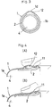
- Figs. 2, 3 show an example of a radiation thermometer according to a second embodiment.
- This radiation thermometer is characterized in that an infrared radiation member 1 is provided with a pressurizing chamber 12 having an air intake 11 and positioned at the circumferential portion 1b of said member 1. Said chamber 12 is used for generating within an air tight room 4 an internal pressure which is higher than a pressure of the open air.
- reference numeral 13 designates an air tight packing disposed between a hood 2 and a body 6.
- the circumferential portion 1b may be thick-walled and a part of the thick-walled portion may be hollowed.
- the circumferential portion 1b is thick-walled and provided with a thin-walled swollen portion 1d swollen out from a part thereof and said thin-walled swollen portion 1d is provided with said air intake 11 opened therein to form the pressurizing chamber 12 between the thin-walled swollen portion 1d and said hood 2.
- Other constructions are same as in the preferred embodiment of the first invention, so that their description is omitted.
- a thin film 1a can be surely adhered to a surface S of an object 3 to be measured over a wide range in the same manner as in the first embodiment by pressing said thin film 1a of said infrared radiation member 1 against said surface S of said object 3 to be measured even in the case where the minimum measurable spot is set so as to be large.
- the internal pressure can be easily and speedily returned to the original high level by conducting the similar operation.
- the present invention can exhibit the following effects on account of the above described constructions: According to the first embodiment, since the air tight room is formed within the infrared radiation member and the internal pressure within the air tight room is higher than the pressure of the open air, the thin film portion can be surely adhered to the surface of the object to be measured by pressing the thin film portion against the surface of the object to be measured and thus a superior conact condition can be achieved even in the case where the area of the thin film portion of the infrared radiation member is increased and the minimum measurable spot is large.
- the internal pressure within the air tight room can be easily and speedily returned to the condition that it is higher than the pressure of the open air by pressing the pressurizing chamber under the condition that the air intake is closed in case the air is leaked from the air tight room due to the repeated use of the radiation thermometer.
Landscapes
- Physics & Mathematics (AREA)
- General Physics & Mathematics (AREA)
- Spectroscopy & Molecular Physics (AREA)
- Radiation Pyrometers (AREA)
Applications Claiming Priority (2)
| Application Number | Priority Date | Filing Date | Title |
|---|---|---|---|
| JP2333566A JP3012316B2 (ja) | 1990-11-29 | 1990-11-29 | 放射温度計 |
| JP333566/90 | 1990-11-29 |
Publications (3)
| Publication Number | Publication Date |
|---|---|
| EP0488284A2 true EP0488284A2 (de) | 1992-06-03 |
| EP0488284A3 EP0488284A3 (en) | 1993-01-13 |
| EP0488284B1 EP0488284B1 (de) | 1995-01-25 |
Family
ID=18267482
Family Applications (1)
| Application Number | Title | Priority Date | Filing Date |
|---|---|---|---|
| EP91120397A Expired - Lifetime EP0488284B1 (de) | 1990-11-29 | 1991-11-28 | Strahlungspyrometer |
Country Status (4)
| Country | Link |
|---|---|
| US (1) | US5188459A (de) |
| EP (1) | EP0488284B1 (de) |
| JP (1) | JP3012316B2 (de) |
| DE (1) | DE69107028D1 (de) |
Families Citing this family (21)
| Publication number | Priority date | Publication date | Assignee | Title |
|---|---|---|---|---|
| JP3052379B2 (ja) * | 1990-12-29 | 2000-06-12 | オムロン株式会社 | 耳式放射体温計 |
| JP2712024B2 (ja) * | 1992-09-19 | 1998-02-10 | 株式会社堀場製作所 | 鼓膜温度計用検鏡カバー |
| US5411032A (en) * | 1993-06-18 | 1995-05-02 | Infra-Temp Inc. | Electronic thermometer probe cover |
| TW410272B (en) * | 1996-05-07 | 2000-11-01 | Thermoscan Lnc | Enhanced protective lens cover |
| CA2251268A1 (en) * | 1996-05-07 | 1997-11-13 | Thermoscan, Inc. | Protective cover for an infrared thermometer |
| US6030117A (en) | 1996-11-12 | 2000-02-29 | Trutek, Inc. | Tympanic thermometer probe cover |
| US5833367A (en) | 1996-11-12 | 1998-11-10 | Trutek, Inc. | Tympanic thermometer probe cover |
| US6001066A (en) | 1997-06-03 | 1999-12-14 | Trutek, Inc. | Tympanic thermometer with modular sensing probe |
| US5944179A (en) * | 1998-05-26 | 1999-08-31 | Walker; Diana G. | Protective sheath for medical probe |
| US5967992A (en) | 1998-06-03 | 1999-10-19 | Trutex, Inc. | Radiometric temperature measurement based on empirical measurements and linear functions |
| US6123454A (en) | 1999-06-11 | 2000-09-26 | Trutek, Inc. | Tympanic thermometer disposable probe cover with further stretching prevention structure |
| US6645612B2 (en) | 2001-08-07 | 2003-11-11 | Saint-Gobain Ceramics & Plastics, Inc. | High solids hBN slurry, hBN paste, spherical hBN powder, and methods of making and using them |
| CN1720429B (zh) * | 2003-01-06 | 2011-07-13 | 舍伍德服务公开股份有限公司 | 鼓膜体温计的探头盖 |
| US7686506B2 (en) | 2003-01-06 | 2010-03-30 | Covidien Ag | Stackable tympanic thermometer probe cover cassette |
| US7354194B2 (en) | 2003-01-06 | 2008-04-08 | Covidien Ag | Tympanic thermometer probe cover with film support mechanism |
| US7478946B2 (en) * | 2003-01-06 | 2009-01-20 | Covidien Ag | Probe cover cassette with improved probe cover support |
| US20070248141A1 (en) * | 2006-04-21 | 2007-10-25 | Sherwood Services Ag | Infrared thermometer and probe cover thereof |
| US7556424B2 (en) * | 2006-05-19 | 2009-07-07 | Covidien Ag | Tympanic thermometer prove cover cassette and holder |
| US8136985B2 (en) * | 2009-05-05 | 2012-03-20 | Welch Allyn, Inc. | IR thermometer thermal isolation tip assembly |
| JP6157988B2 (ja) * | 2013-08-21 | 2017-07-05 | 株式会社東芝 | 組電池モジュール |
| JP2015135316A (ja) * | 2013-12-17 | 2015-07-27 | 株式会社テイエルブイ | 温度測定装置 |
Family Cites Families (10)
| Publication number | Priority date | Publication date | Assignee | Title |
|---|---|---|---|---|
| US3703892A (en) * | 1970-12-09 | 1972-11-28 | Edward F Meyers | Disposable, retractable thermometer jacket |
| US3942891A (en) * | 1975-01-29 | 1976-03-09 | Barnes Engineering Company | Radiometer probe |
| US4052899A (en) * | 1975-04-04 | 1977-10-11 | Semperit Anstalt | Depthometer for underwater immersion |
| US4341992A (en) * | 1980-01-21 | 1982-07-27 | Control Electronics Co., Inc. | Conductive probe cover |
| US4662360A (en) * | 1984-10-23 | 1987-05-05 | Intelligent Medical Systems, Inc. | Disposable speculum |
| US4752141A (en) * | 1985-10-25 | 1988-06-21 | Luxtron Corporation | Fiberoptic sensing of temperature and/or other physical parameters |
| US4895164A (en) * | 1988-09-15 | 1990-01-23 | Telatemp Corp. | Infrared clinical thermometer |
| US5018872A (en) * | 1988-11-01 | 1991-05-28 | Diatek, Inc. | Probe assembly for infrared thermometer |
| US5066142A (en) * | 1990-03-08 | 1991-11-19 | Ivac Corporation | Protective apparatus for a biomedical probe |
| US5088834A (en) * | 1990-08-24 | 1992-02-18 | Thermoscan Inc. | Unitary probe cover |
-
1990
- 1990-11-29 JP JP2333566A patent/JP3012316B2/ja not_active Expired - Fee Related
-
1991
- 1991-11-26 US US07/797,906 patent/US5188459A/en not_active Expired - Fee Related
- 1991-11-28 DE DE69107028T patent/DE69107028D1/de not_active Expired - Lifetime
- 1991-11-28 EP EP91120397A patent/EP0488284B1/de not_active Expired - Lifetime
Also Published As
| Publication number | Publication date |
|---|---|
| EP0488284A3 (en) | 1993-01-13 |
| JPH04203941A (ja) | 1992-07-24 |
| DE69107028D1 (de) | 1995-03-09 |
| JP3012316B2 (ja) | 2000-02-21 |
| EP0488284B1 (de) | 1995-01-25 |
| US5188459A (en) | 1993-02-23 |
Similar Documents
| Publication | Publication Date | Title |
|---|---|---|
| EP0488284B1 (de) | Strahlungspyrometer | |
| CA1314407E (en) | Infrared electronic thermometer and method for measuring temperature | |
| USRE34789E (en) | Infrared electronic thermometer and method for measuring temperature | |
| US5066142A (en) | Protective apparatus for a biomedical probe | |
| US4831258A (en) | Dual sensor radiation detector | |
| US6241384B1 (en) | Axillary infrared thermometer and method of use | |
| US4998438A (en) | Digital air pressure gauge and inflation device | |
| DE68916832T2 (de) | Klinisches Strahlungsthermometer. | |
| AU5821299A (en) | Temporal artery temperature detector | |
| EP1324012A3 (de) | Kontaktloser Temperatursensor und zugehörige Detektionsschaltung | |
| CA2264193A1 (en) | A tonometer system for measuring intraocular pressure by applanation and/or indentation | |
| DK104386A (da) | Apparat til proevning af beholdere for laekager og defekter | |
| EP0374735B1 (de) | Optischer Monitor zur superplastischen Verformung | |
| KR20000029960A (ko) | 간극감지장치및방법 | |
| JPS57191507A (en) | Distance measuring device | |
| DK0537246T3 (da) | Lukkeindretning til en flaske eller lignende | |
| IE812735L (en) | Radiation sensing device | |
| US20020186745A1 (en) | Axillary infrared thermometer and method of use | |
| JPH06174553A (ja) | 金型温度測定方法 | |
| JP2000254103A (ja) | 放射温度計 | |
| JPH0216425A (ja) | 温度測定装置 | |
| EP0247789A3 (de) | Messung und Aufzeichnung eines Gasbestandteils | |
| JPS57212886A (en) | Reproducer for picture of temperature distribution | |
| JPS6025428A (ja) | 非接触型温度センサ | |
| JPS61178624A (ja) | 表面温度測定方法及び装置 |
Legal Events
| Date | Code | Title | Description |
|---|---|---|---|
| PUAI | Public reference made under article 153(3) epc to a published international application that has entered the european phase |
Free format text: ORIGINAL CODE: 0009012 |
|
| AK | Designated contracting states |
Kind code of ref document: A2 Designated state(s): DE FR GB |
|
| RIN1 | Information on inventor provided before grant (corrected) |
Inventor name: TSUJIOKA, YUIJI, HAMMING NISHIURA 302 GO SHITSU, Inventor name: NOMURA, TOSHIYUKI Inventor name: MINO, KAZUO |
|
| PUAL | Search report despatched |
Free format text: ORIGINAL CODE: 0009013 |
|
| AK | Designated contracting states |
Kind code of ref document: A3 Designated state(s): DE FR GB |
|
| 17P | Request for examination filed |
Effective date: 19930201 |
|
| 17Q | First examination report despatched |
Effective date: 19940322 |
|
| GRAA | (expected) grant |
Free format text: ORIGINAL CODE: 0009210 |
|
| AK | Designated contracting states |
Kind code of ref document: B1 Designated state(s): DE FR GB |
|
| PG25 | Lapsed in a contracting state [announced via postgrant information from national office to epo] |
Ref country code: FR Effective date: 19950125 |
|
| REF | Corresponds to: |
Ref document number: 69107028 Country of ref document: DE Date of ref document: 19950309 |
|
| PG25 | Lapsed in a contracting state [announced via postgrant information from national office to epo] |
Ref country code: DE Effective date: 19950426 |
|
| EN | Fr: translation not filed | ||
| PLBE | No opposition filed within time limit |
Free format text: ORIGINAL CODE: 0009261 |
|
| STAA | Information on the status of an ep patent application or granted ep patent |
Free format text: STATUS: NO OPPOSITION FILED WITHIN TIME LIMIT |
|
| PG25 | Lapsed in a contracting state [announced via postgrant information from national office to epo] |
Ref country code: GB Effective date: 19951128 |
|
| 26N | No opposition filed | ||
| GBPC | Gb: european patent ceased through non-payment of renewal fee |
Effective date: 19951128 |