EP0487906A2 - Abgedeckter elektrischer Verbinder - Google Patents
Abgedeckter elektrischer Verbinder Download PDFInfo
- Publication number
- EP0487906A2 EP0487906A2 EP91118299A EP91118299A EP0487906A2 EP 0487906 A2 EP0487906 A2 EP 0487906A2 EP 91118299 A EP91118299 A EP 91118299A EP 91118299 A EP91118299 A EP 91118299A EP 0487906 A2 EP0487906 A2 EP 0487906A2
- Authority
- EP
- European Patent Office
- Prior art keywords
- male
- terminal
- shroud
- contact portion
- shroud portion
- Prior art date
- Legal status (The legal status is an assumption and is not a legal conclusion. Google has not performed a legal analysis and makes no representation as to the accuracy of the status listed.)
- Granted
Links
Images
Classifications
-
- H—ELECTRICITY
- H01—ELECTRIC ELEMENTS
- H01R—ELECTRICALLY-CONDUCTIVE CONNECTIONS; STRUCTURAL ASSOCIATIONS OF A PLURALITY OF MUTUALLY-INSULATED ELECTRICAL CONNECTING ELEMENTS; COUPLING DEVICES; CURRENT COLLECTORS
- H01R13/00—Details of coupling devices of the kinds covered by groups H01R12/70 or H01R24/00 - H01R33/00
- H01R13/02—Contact members
- H01R13/10—Sockets for co-operation with pins or blades
- H01R13/11—Resilient sockets
-
- H—ELECTRICITY
- H01—ELECTRIC ELEMENTS
- H01R—ELECTRICALLY-CONDUCTIVE CONNECTIONS; STRUCTURAL ASSOCIATIONS OF A PLURALITY OF MUTUALLY-INSULATED ELECTRICAL CONNECTING ELEMENTS; COUPLING DEVICES; CURRENT COLLECTORS
- H01R13/00—Details of coupling devices of the kinds covered by groups H01R12/70 or H01R24/00 - H01R33/00
- H01R13/02—Contact members
- H01R13/04—Pins or blades for co-operation with sockets
Definitions
- This invention generally relates to the art of electrical connectors and, particularly, to a male terminal which has an integral shroud for protecting a male contact.
- One example is in manufacturing windows having conductors imbedded therein for defogging purposes.
- the windows are fabricated separately and then assembled to the final product.
- connectors are used to couple the window conductor to some form of electrical wiring harness on the automobile. It would be desirable to have an electrical connector component already attached or coupled to the window and shipped in that condition so that the window simply is assembled to the automobile and readily coupled in-circuit with the separately assembled wiring harness.
- an electrical connector component will be exposed during manufacture, shipping and handling and is prone to be damaged during such movement.
- This invention is directed to solving the problems outlined above by providing a male terminal for an electrical connector assembly which is very easy and inexpensive to manufacture and which has an integral shroud for protecting the male contact portion of the terminal.
- An object, therefore, of the invention is to provide a new and improved male terminal having integral protection for a male contact portion thereof.
- Another object of the invention is to provide an electrical connector assembly which includes the male terminal of the invention and a complementary electrical connector which has a female terminal and a housing for receiving the novel male terminal.
- the invention contemplates providing a male terminal having a male contact portion and a shroud portion about the male contact portion.
- the male contact portion is integral with and folded into the interior of the shroud portion whereby the shroud portion protects the male contact portion.
- the male terminal is fabricated as a one-piece structure of stamped and formed metal.
- the shroud portion is generally hollow with opposite ends.
- the male contact portion is folded inwardly from one end of the hollow shroud portion.
- the male contact portion also is folded onto itself to form a double thickness therefor.
- the shroud portion is generally rectangularly shaped in cross-section.
- the shroud portion of the male terminal has terminating means on the outside thereof for coupling the terminal in an appropriate circuit.
- the terminating means is shown herein as a solder pad for soldering to a complementary solder pad on the surface of a glass window.
- the terminal can be appropriately terminated to a defogging conductor imbedded in the window glass.
- the invention also contemplates providing an electrical connector assembly which includes a female connector having a housing with a female terminal.
- the female terminal mates with the male contact portion of the male terminal, and the housing has channel means for receiving the shroud portion of the male terminal surrounding the male contact portion.
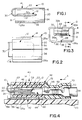
- male terminal 10 which includes a male contact portion, generally designated 12, and a shroud portion, generally designated 14, about male contact 12.
- Male terminal 10 is fabricated as a one-piece structure of stamped and formed metal material.
- shroud 14 of male terminal 10 is tubular in shape to define a hollow interior 16 and opposite open ends 18 and 20.
- the shroud is generally rectangularly shaped in cross-section as seen in Figure 3 and as defined by a top wall 22, opposite side walls 24 and bottom wall portions 26a which meet at a split line 28.
- the shroud is easily formed from a stamped metal blank by folding the metal into the rectangular configuration, with opposite side edges of the blank meeting at split line 28.
- Male contact 12 is formed from the metal blank prior to folding the shroud thereabout.
- the male contact forms an extension of top wall 22 of the shroud, as best seen in Figure 1, and is folded, as at 30, back under the top wall so as to be generally centrally disposed within the hollow interior 16 of the shroud.
- male contact 12 is in the form of a flat blade 32 which has a double thickness provided by folding side portions 32a back over the top of blade 32 whereby they substantially meet at a split line 34 (Fig. 3).
- male contact 12 is substantially entirely surrounded by shroud 14 and is protected by the shroud during shipping, handling, or assembly.
- male terminal 10 includes terminating means thereon for coupling the terminal in an appropriate circuit.
- the terminating means are provided in the form of a bifurcated solder pad 36 pre attached to the buttom wall portions 26a of shroud 14 prior to the stamping and forming fabrication operation.
- the pad is attached to the bottom wall of the shroud, the solder pad including a split line 38 (Fig. 3) aligned with split line 28 in the bottom wall of the shroud.
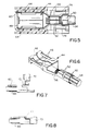
- the invention contemplates providing an electrical connector assembly, generally designated 40 (Fig. 4) which includes a female connector, generally designated 42, for meeting with male terminal 10.
- female connector 42 includes a housing mounting a female terminal, generally designated 44, therewithin.
- female terminal 44 includes a female receptacle portion having inwardly directed spring arms 46 on opposite sides of a receptacle area 48.
- the female terminal includes two pairs of crimp arms 50 and 52.
- Crimp arms 50 are crimped onto an electrical wire 54, and crimp arms 52 are crimped onto exposed conductors 56 of the wire.
- spring arms 46 are located within an interior cavity 58 of the female connector housing.
- Male contact 12 of male terminal 10 is insertable through a mouth 60 of the housing, into cavity 58 and into engagement with spring arms 48 of female terminal 44 for mating therewith and establishing an electrical connection therethrough.
- the housing of female connector 42 also includes channel means for receiving shroud 14 of male terminal 10.
- the channel means is generally rectangularly shaped for receiving the walls of the rectangularly shaped shroud.
- the channel means includes a top channel 62 (Fig. 4) for receiving top wall 22 of the shroud, side channels 64 (Fig. 5) for receiving side walls 24 of the shroud and an open or recessed area 66 (Fig. 4) at the bottom of the housing for receiving bottom wall 26a of the shroud.
- female connector 42 is mated with male terminal 10 in the direction of arrow "A" (Fig. 4) whereby male contact 12 moves into female contact 44 between spring arms 46, and the walls 22, 24 and 26a move into channels or recesses 62, 64 and 66, respectively, of the female connector housing.
- FIGs 7 and 8 simply show that female connector 42 includes a housing portion 70 joined to the remainder of the connector housing by a living hinge 72 whereby the housing portion is movable between an open or terminal loading position shown in Figure 7 to allow loading of the female terminal 44 into the female connector, and a closed or locked position shown in Figure 8 to surround the crimped areas of the female terminal.
- Snap latch flanges 74 (Fig. 5) lock the housing portion in its closed position.
- the entire housing of female connector 42, including hinged portion 70, is unitarily fabricated of molded material, such as plastic or the like.
- terminating means in the form of a split solder pad 36 is provided on the outside of shroud 14 of male terminal 10, particularly attached to the bottom wall 26a of the terminal.
- solder pad 36 With recessed area 66 (Fig. 4) of female connector 42 being open at the bottom of the connector, solder pad 36 is exposed at the bottom of the connector assembly.
- Item 80 in Figure 4 represents a glass panel, such the rear window of an automobile.
- the window includes conductors, one of which is shown at 82, providing defogging means for the window.
- a solder pad 84 is attached to the surface of the glass, as by an appropriate adhesive, and is electrically coupled to conductor 82.
- solder pad 36 on the bottom of male terminal 10 is soldered to solder pad 84 on the window, thereby to electrically couple the male terminal to the defogging conductor(s) imbedded within the window glass.
- Female connector 42 including female terminal 44, would comprise a termination with an electrical harness of the automobile whereby defogging conductor(s) 82 can be electrically coupled through male terminal 10 to the electrical power source of the automobile.
- the solder pad increases the strength of shroud 14 when soldered to solder pad 84 on the rigid window glass. With male contact 12 being substantially surrounded by the shroud, the male contact is completely protected when the male terminal is fixed to the glass panel. It can be seen that the configuration of the male terminal provides a low profile, and the shroud acts as a heat sink in high amperage conditions.
Landscapes
- Connector Housings Or Holding Contact Members (AREA)
- Details Of Connecting Devices For Male And Female Coupling (AREA)
- Coupling Device And Connection With Printed Circuit (AREA)
Applications Claiming Priority (2)
| Application Number | Priority Date | Filing Date | Title |
|---|---|---|---|
| US619576 | 1990-11-29 | ||
| US07/619,576 US5098320A (en) | 1990-11-29 | 1990-11-29 | Shrouded electrical connector |
Publications (3)
| Publication Number | Publication Date |
|---|---|
| EP0487906A2 true EP0487906A2 (de) | 1992-06-03 |
| EP0487906A3 EP0487906A3 (en) | 1993-04-14 |
| EP0487906B1 EP0487906B1 (de) | 1996-03-13 |
Family
ID=24482470
Family Applications (1)
| Application Number | Title | Priority Date | Filing Date |
|---|---|---|---|
| EP91118299A Expired - Lifetime EP0487906B1 (de) | 1990-11-29 | 1991-10-26 | Abgedeckter elektrischer Verbinder |
Country Status (5)
| Country | Link |
|---|---|
| US (1) | US5098320A (de) |
| EP (1) | EP0487906B1 (de) |
| JP (1) | JP2538818B2 (de) |
| KR (1) | KR970000286B1 (de) |
| DE (1) | DE69117887T2 (de) |
Families Citing this family (9)
| Publication number | Priority date | Publication date | Assignee | Title |
|---|---|---|---|---|
| GB9301465D0 (en) * | 1993-01-26 | 1993-03-17 | Amp Gmbh | Electrical terminal receptacle with improved means for connecting two electrical conducting tables and a method for manufacturing it |
| US5342226A (en) * | 1993-06-21 | 1994-08-30 | Electro-Wire Products, Inc. | Female blade terminal |
| US5897406A (en) * | 1997-08-15 | 1999-04-27 | Molex Incorporated | Electrical terminal for glass sheets |
| US6840780B1 (en) | 2002-07-26 | 2005-01-11 | Antaya Technologies Corporation | Non-solder adhesive terminal |
| US7416922B2 (en) * | 2003-03-31 | 2008-08-26 | Intel Corporation | Heat sink with preattached thermal interface material and method of making same |
| US7014093B2 (en) * | 2003-06-26 | 2006-03-21 | Intel Corporation | Multi-layer polymer-solder hybrid thermal interface material for integrated heat spreader and method of making same |
| US7527090B2 (en) * | 2003-06-30 | 2009-05-05 | Intel Corporation | Heat dissipating device with preselected designed interface for thermal interface materials |
| DE102007051870A1 (de) * | 2007-10-30 | 2009-05-07 | Robert Bosch Gmbh | Modulgehäuse und Verfahren zur Herstellung eines Modulgehäuses |
| US10453587B2 (en) * | 2015-12-22 | 2019-10-22 | Panasonic Intellectual Property Management Co., Ltd. | Conductor assembly, electronic component using same, and manufacturing method thereof |
Family Cites Families (6)
| Publication number | Priority date | Publication date | Assignee | Title |
|---|---|---|---|---|
| US3188600A (en) * | 1960-09-12 | 1965-06-08 | Gen Motors Corp | Terminal and mounting means |
| US3550067A (en) * | 1968-04-29 | 1970-12-22 | Molex Products Co | Electrical receptacle and terminal |
| GB1490195A (en) * | 1973-12-28 | 1977-10-26 | Rists Wires & Cables Ltd | Electrical terminals |
| JPS5723963Y2 (de) * | 1978-07-03 | 1982-05-24 | ||
| DE8303418U1 (de) * | 1983-02-08 | 1983-05-26 | Siemens AG, 1000 Berlin und 8000 München | Kontakelement für Leiterplatten |
| DE3817803C3 (de) * | 1988-05-26 | 1995-04-20 | Reinshagen Kabelwerk Gmbh | Elektrische Flachsteckverbindung |
-
1990
- 1990-11-29 US US07/619,576 patent/US5098320A/en not_active Expired - Fee Related
-
1991
- 1991-10-26 DE DE69117887T patent/DE69117887T2/de not_active Expired - Fee Related
- 1991-10-26 EP EP91118299A patent/EP0487906B1/de not_active Expired - Lifetime
- 1991-11-25 JP JP3335792A patent/JP2538818B2/ja not_active Expired - Lifetime
- 1991-11-28 KR KR1019910021505A patent/KR970000286B1/ko not_active Expired - Fee Related
Also Published As
| Publication number | Publication date |
|---|---|
| KR970000286B1 (ko) | 1997-01-08 |
| US5098320A (en) | 1992-03-24 |
| JP2538818B2 (ja) | 1996-10-02 |
| EP0487906A3 (en) | 1993-04-14 |
| DE69117887T2 (de) | 1996-10-24 |
| JPH04286879A (ja) | 1992-10-12 |
| DE69117887D1 (de) | 1996-04-18 |
| EP0487906B1 (de) | 1996-03-13 |
| KR920010994A (ko) | 1992-06-27 |
Similar Documents
| Publication | Publication Date | Title |
|---|---|---|
| US4657331A (en) | Strain relief for electrical connector assemblies | |
| US5902155A (en) | Electrical connector assembly | |
| KR100288726B1 (ko) | 유리판용 전기 단자 | |
| US5980335A (en) | Electrical terminal | |
| US4169648A (en) | Strain relief and back cover for electrical connector | |
| US4163598A (en) | Point-to-point miniature coax connector | |
| EP0590544B1 (de) | Abgeschirmter elektrischer Stecker | |
| US5273453A (en) | Electrical connector with positive latch | |
| KR19990036991A (ko) | 가요성 평면 회로용 커넥터 | |
| KR19990036992A (ko) | 가요성 평면 회로용 수형 커넥터 | |
| JP2005505104A (ja) | 自動車用大電流電気コネクタ及び端子 | |
| JPH10503319A (ja) | 電気端子 | |
| JP2001093606A (ja) | 回路基板実装用電気コネクタ | |
| US6000974A (en) | Universal contact receptacle | |
| US5098320A (en) | Shrouded electrical connector | |
| CA1192971A (en) | Electrical connector | |
| US5186644A (en) | Electrical connector system | |
| EP0840402A2 (de) | Verbinder | |
| EP0893843A1 (de) | Modularer koaxialer Verbinder | |
| JPS64791B2 (de) | ||
| EP1037329A2 (de) | Electrischer Schaltverbinder | |
| JP3034347U (ja) | ひずみ解放手段を有する帯状ケーブル用電気コネクタ | |
| JP3085691B2 (ja) | ジョイントコネクタ | |
| EP0503380B1 (de) | Elektrische Verbinderanordnung | |
| JPH09320699A (ja) | 同軸コネクター |
Legal Events
| Date | Code | Title | Description |
|---|---|---|---|
| PUAI | Public reference made under article 153(3) epc to a published international application that has entered the european phase |
Free format text: ORIGINAL CODE: 0009012 |
|
| AK | Designated contracting states |
Kind code of ref document: A2 Designated state(s): DE FR GB IT |
|
| PUAL | Search report despatched |
Free format text: ORIGINAL CODE: 0009013 |
|
| AK | Designated contracting states |
Kind code of ref document: A3 Designated state(s): DE FR GB IT |
|
| 17P | Request for examination filed |
Effective date: 19930922 |
|
| 17Q | First examination report despatched |
Effective date: 19940119 |
|
| ITF | It: translation for a ep patent filed | ||
| GRAA | (expected) grant |
Free format text: ORIGINAL CODE: 0009210 |
|
| AK | Designated contracting states |
Kind code of ref document: B1 Designated state(s): DE FR GB IT |
|
| REF | Corresponds to: |
Ref document number: 69117887 Country of ref document: DE Date of ref document: 19960418 |
|
| ET | Fr: translation filed | ||
| PLBE | No opposition filed within time limit |
Free format text: ORIGINAL CODE: 0009261 |
|
| STAA | Information on the status of an ep patent application or granted ep patent |
Free format text: STATUS: NO OPPOSITION FILED WITHIN TIME LIMIT |
|
| 26N | No opposition filed | ||
| PGFP | Annual fee paid to national office [announced via postgrant information from national office to epo] |
Ref country code: GB Payment date: 19990913 Year of fee payment: 9 |
|
| PGFP | Annual fee paid to national office [announced via postgrant information from national office to epo] |
Ref country code: FR Payment date: 19991013 Year of fee payment: 9 |
|
| PGFP | Annual fee paid to national office [announced via postgrant information from national office to epo] |
Ref country code: DE Payment date: 19991027 Year of fee payment: 9 |
|
| PG25 | Lapsed in a contracting state [announced via postgrant information from national office to epo] |
Ref country code: GB Free format text: LAPSE BECAUSE OF NON-PAYMENT OF DUE FEES Effective date: 20001026 |
|
| GBPC | Gb: european patent ceased through non-payment of renewal fee |
Effective date: 20001026 |
|
| PG25 | Lapsed in a contracting state [announced via postgrant information from national office to epo] |
Ref country code: FR Free format text: LAPSE BECAUSE OF NON-PAYMENT OF DUE FEES Effective date: 20010629 |
|
| PG25 | Lapsed in a contracting state [announced via postgrant information from national office to epo] |
Ref country code: DE Free format text: LAPSE BECAUSE OF NON-PAYMENT OF DUE FEES Effective date: 20010703 |
|
| REG | Reference to a national code |
Ref country code: FR Ref legal event code: ST |
|
| PG25 | Lapsed in a contracting state [announced via postgrant information from national office to epo] |
Ref country code: IT Free format text: LAPSE BECAUSE OF NON-PAYMENT OF DUE FEES;WARNING: LAPSES OF ITALIAN PATENTS WITH EFFECTIVE DATE BEFORE 2007 MAY HAVE OCCURRED AT ANY TIME BEFORE 2007. THE CORRECT EFFECTIVE DATE MAY BE DIFFERENT FROM THE ONE RECORDED. Effective date: 20051026 |