EP0486732A1 - Optische Mikroskope - Google Patents
Optische Mikroskope Download PDFInfo
- Publication number
- EP0486732A1 EP0486732A1 EP90312592A EP90312592A EP0486732A1 EP 0486732 A1 EP0486732 A1 EP 0486732A1 EP 90312592 A EP90312592 A EP 90312592A EP 90312592 A EP90312592 A EP 90312592A EP 0486732 A1 EP0486732 A1 EP 0486732A1
- Authority
- EP
- European Patent Office
- Prior art keywords
- lens
- light
- objective lens
- microscope
- plane
- Prior art date
- Legal status (The legal status is an assumption and is not a legal conclusion. Google has not performed a legal analysis and makes no representation as to the accuracy of the status listed.)
- Ceased
Links
- 230000003287 optical effect Effects 0.000 title description 10
- 230000008878 coupling Effects 0.000 claims abstract description 17
- 238000010168 coupling process Methods 0.000 claims abstract description 17
- 238000005859 coupling reaction Methods 0.000 claims abstract description 17
- 230000001419 dependent effect Effects 0.000 claims 1
- 238000006073 displacement reaction Methods 0.000 description 5
- 239000004065 semiconductor Substances 0.000 description 4
- 230000004048 modification Effects 0.000 description 3
- 238000012986 modification Methods 0.000 description 3
- 239000011859 microparticle Substances 0.000 description 2
- 230000000903 blocking effect Effects 0.000 description 1
- 230000000694 effects Effects 0.000 description 1
- 230000001678 irradiating effect Effects 0.000 description 1
- 230000005855 radiation Effects 0.000 description 1
Images


Classifications
-
- G—PHYSICS
- G02—OPTICS
- G02B—OPTICAL ELEMENTS, SYSTEMS OR APPARATUS
- G02B21/00—Microscopes
- G02B21/0004—Microscopes specially adapted for specific applications
- G02B21/002—Scanning microscopes
-
- G—PHYSICS
- G02—OPTICS
- G02B—OPTICAL ELEMENTS, SYSTEMS OR APPARATUS
- G02B21/00—Microscopes
- G02B21/06—Means for illuminating specimens
- G02B21/08—Condensers
- G02B21/082—Condensers for incident illumination only
Definitions
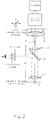
- This invention relates to optical microscopes having supplementary means for delivering a beam of light into an optical microscope so that:
- the invention is intended to be used in conjunction with a semiconductor laser to produce a spot of light small enough to create electromagnetic gradient forces for trapping micro-particles and living cells.
- a microscope is provided with a supplementary means for producing a light spot S in the object plane of the microscope objective lens, the means comprising a light source from which a collimated light beam is derived, a focusing lens L1 receiving the collimated beam and a coupling lens L2 disposed between said first lens L1 and the objective lens MO whereby a light spot is produced from said collimated beam in the object plane of the objective lens MO, (i) the focal point F of the focusing lens L1 being in the plane of the image of a specimen in said object plane as obtained through the objective lens MO and the coupling lens L2, (ii) the light beam filling the clear aperture of the objective lens MO without substantial light loss and (iii) the focusing lens L1 being movable in a plane perpendicular to its axis to displace the light spot S in the object plane of the objective lens MO, the parameters of the system being such that the axial ray of light from said light source always passes through the second principal point (i.e. that on the
- the focusing lens L1 may additionally be capable of limited movement parallel to its axis so that the light spot is displaced a short distance from the object plane of the objective lens MO.
- the light source is moved together with the focusing lens L1 perpendicularly to said axis.
- the focusing lens L1 is movable perpendicularly to said axis relatively to the collimated light beam.
- the focal point F of the focusing lens L1 is arranged in the plane of the image of the specimen as obtained through the objective lens MO and the coupling lens L2. This has the effect of adapting a parallel beam of light to the finite conjugate ratio of the majority of microscope objective lenses by making the beam divergent.
- the light produced by a semi-conductor laser can be collimated by means of lenses, prisms or a combination of both into a beam of circular cross-section.
- a beam can have divergence sufficiently low that it results in an additional contribution to the size of the final spot of light produced by the present invention comparable in magnitude or smaller than the size pertaining to formula (1).
- the present invention is used in conjunction with a semi-conductor laser and a collimator producing a quasi-parallel beam of sufficiently low divergence the size of the spot of light can be close to or less than 1 ⁇ m.
- the formulae for the first embodiment may be derived as follows. It is assumed that all distances are measured between appropriate principal points of the lenses.
- ⁇ 2 ⁇ 1(d/
- the distance d between the focusing lens L1 and the coupling lens L2 from formula (2) (note again that f1 can be either positive or negative, depending on the type of the lens L1).
- the length l is equal to the object-to-image distance of the microscope (usually 195mm) less the focal length f3 of the objective lens.
- the formulae for the second embodiment may be derived as follows. It is again assumed that all distances are measured between appropriate principal points of the lenses.
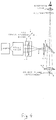
- the viewing path and laser beam path have been interchanged as compared with Figures 1 and 2 respectively.
- the mirror M should transmit a substantial part of the visible light originating from the specimen and reflect a substantial part of the light emitted by the laser.
- the mirror M can be such that it reflects most of the visible light (used for viewing) and transmits most of the laser light (used for producing the light spot) in the case of the embodiments shown in Figures 1 and 2. Again, the reverse should be the case for the embodiments shown in Figures 3 and 4.
- the above can be accomplished with the aid of an interference filter designed for oblique incidence. Such a filter can be chosen to transmit and reflect only at desired wavelengths or wavelength ranges and thus separate the viewing path from the laser light path more efficiently.
- a laser providing a collimated beam can be used rather than a separate collimator being provided.
Landscapes
- Physics & Mathematics (AREA)
- Chemical & Material Sciences (AREA)
- Analytical Chemistry (AREA)
- General Physics & Mathematics (AREA)
- Optics & Photonics (AREA)
- Microscoopes, Condenser (AREA)
Applications Claiming Priority (1)
| Application Number | Priority Date | Filing Date | Title |
|---|---|---|---|
| GB8910307A GB2231681B (en) | 1989-05-05 | 1989-05-05 | Optical microscopes |
Publications (1)
| Publication Number | Publication Date |
|---|---|
| EP0486732A1 true EP0486732A1 (de) | 1992-05-27 |
Family
ID=10656248
Family Applications (1)
| Application Number | Title | Priority Date | Filing Date |
|---|---|---|---|
| EP90312592A Ceased EP0486732A1 (de) | 1989-05-05 | 1990-11-20 | Optische Mikroskope |
Country Status (3)
| Country | Link |
|---|---|
| US (1) | US5225929A (de) |
| EP (1) | EP0486732A1 (de) |
| GB (1) | GB2231681B (de) |
Cited By (1)
| Publication number | Priority date | Publication date | Assignee | Title |
|---|---|---|---|---|
| WO2001035150A1 (de) * | 1999-11-10 | 2001-05-17 | Carl Zeiss Jena Gmbh | Anordnung zur einkopplung einer optischen pinzette und/oder eines bearbeitungsstrahles in ein mikroskop |
Families Citing this family (5)
| Publication number | Priority date | Publication date | Assignee | Title |
|---|---|---|---|---|
| WO1997034171A2 (en) * | 1996-02-28 | 1997-09-18 | Johnson Kenneth C | Microlens scanner for microlithography and wide-field confocal microscopy |
| US6251101B1 (en) | 1998-06-26 | 2001-06-26 | Visx, Incorporated | Surgical laser system microscope with separated ocular and objective lenses |
| US6898006B2 (en) * | 2001-12-26 | 2005-05-24 | Olympus Optical Co., Ltd. | Microscope |
| US7282729B2 (en) * | 2003-08-20 | 2007-10-16 | Xyratex Technology Limited | Fabry-Perot resonator apparatus and method for observing low reflectivity surfaces |
| US11506877B2 (en) | 2016-11-10 | 2022-11-22 | The Trustees Of Columbia University In The City Of New York | Imaging instrument having objective axis and light sheet or light beam projector axis intersecting at less than 90 degrees |
Citations (3)
| Publication number | Priority date | Publication date | Assignee | Title |
|---|---|---|---|---|
| US3460880A (en) * | 1964-12-18 | 1969-08-12 | Beckman Instruments Inc | Point illumination and scanning mechanism for microscopes |
| DE2443167A1 (de) * | 1974-09-10 | 1976-03-25 | Strahlen Umweltforsch Gmbh | Scharfeinstellvorrichtung |
| US4523799A (en) * | 1981-12-04 | 1985-06-18 | Agence Nationale De Volorisation De La Recherche (Anvar) | Device optimizing the coupling of two optical systems for the observation and analysis of objects |
Family Cites Families (3)
| Publication number | Priority date | Publication date | Assignee | Title |
|---|---|---|---|---|
| JPS52111295A (en) * | 1976-03-15 | 1977-09-17 | Mochida Pharm Co Ltd | Operational laser optical device under microscope |
| DE2843287A1 (de) * | 1977-10-05 | 1979-04-19 | Canon Kk | Augenuntersuchungsinstrument |
| DE3006657A1 (de) * | 1980-02-22 | 1981-09-03 | Ernst Leitz Wetzlar Gmbh, 6330 Wetzlar | Vergleichsmakroskop bzw. -mikroskop |
-
1989
- 1989-05-05 GB GB8910307A patent/GB2231681B/en not_active Expired - Fee Related
-
1990
- 1990-11-20 EP EP90312592A patent/EP0486732A1/de not_active Ceased
-
1991
- 1991-11-18 US US07/793,631 patent/US5225929A/en not_active Expired - Fee Related
Patent Citations (3)
| Publication number | Priority date | Publication date | Assignee | Title |
|---|---|---|---|---|
| US3460880A (en) * | 1964-12-18 | 1969-08-12 | Beckman Instruments Inc | Point illumination and scanning mechanism for microscopes |
| DE2443167A1 (de) * | 1974-09-10 | 1976-03-25 | Strahlen Umweltforsch Gmbh | Scharfeinstellvorrichtung |
| US4523799A (en) * | 1981-12-04 | 1985-06-18 | Agence Nationale De Volorisation De La Recherche (Anvar) | Device optimizing the coupling of two optical systems for the observation and analysis of objects |
Cited By (3)
| Publication number | Priority date | Publication date | Assignee | Title |
|---|---|---|---|---|
| WO2001035150A1 (de) * | 1999-11-10 | 2001-05-17 | Carl Zeiss Jena Gmbh | Anordnung zur einkopplung einer optischen pinzette und/oder eines bearbeitungsstrahles in ein mikroskop |
| JP2003514252A (ja) * | 1999-11-10 | 2003-04-15 | カール ツァイス イエナ ゲゼルシャフト ミット ベシュレンクテル ハフツング | 光学ピンセットおよび/または加工ビームを顕微鏡内へ接続する装置 |
| US6850363B1 (en) | 1999-11-10 | 2005-02-01 | Carl Zeiss Jena Gmbh | System for introducing optical tweezers and/or a treatment beam into a laser scanning microscope |
Also Published As
| Publication number | Publication date |
|---|---|
| GB2231681B (en) | 1993-04-21 |
| US5225929A (en) | 1993-07-06 |
| GB8910307D0 (en) | 1989-06-21 |
| GB2231681A (en) | 1990-11-21 |
Similar Documents
| Publication | Publication Date | Title |
|---|---|---|
| US5288987A (en) | Autofocusing arrangement for a stereomicroscope which permits automatic focusing on objects on which reflections occur | |
| CA1325537C (en) | Confocal microscope | |
| CA2282519C (en) | Fiber-integrated microlenses and optical fiber fbg couplers spectrometers and multiplexers comprised thereof | |
| JP2975719B2 (ja) | 共焦点光学系 | |
| US7167321B1 (en) | Optical systems and methods employing adjacent rotating cylindrical lenses | |
| JPS58217909A (ja) | 光学器械で観察中の対象物に自動的に焦点を合わせる装置 | |
| DE69922139T2 (de) | Strahlteiler mit versetzten oeffnungen fuer sender/empfaenger in einem optomechanischen lasersystem | |
| EP1126306A2 (de) | Vorrichtung zur dynamischen Lichtstrahlsteuerung | |
| US4383741A (en) | Binocular night telescope | |
| CA1109142A (en) | Passive optical range simulator device | |
| GB2220501A (en) | Coupling waveguides using transverse cylindrical lenses | |
| WO2008155241A3 (de) | Vorrichtung zum bearbeiten eines werkstücks mittels eines laserstrahls | |
| EP0072652A1 (de) | Veränderliches Stereomikroskop | |
| EP0486732A1 (de) | Optische Mikroskope | |
| EP0278929B1 (de) | Vorrichtung zur Einrichtung einer Strahlungsquelle, die unsichtbare Laserstrahlung emittiert | |
| KR970703540A (ko) | 광학 광선 분할 소자(Optical beam-splitting element) | |
| US5570189A (en) | Split-field pupil plane determination apparatus | |
| JPS61500395A (ja) | 眼科的処置に適したネオジム・レ−ザ装置 | |
| JPH04501615A (ja) | 無彩色走査装置 | |
| US5130533A (en) | Device for measuring backscattered radiation using a frequency selective element | |
| US4281905A (en) | Magneto-optic light deflector beam recombination apparatus | |
| US4917457A (en) | Beam separating prism | |
| JPS57197511A (en) | Focusing device for binocular stereoscopic microscope | |
| US5013120A (en) | Monochromator to fiber-cable coupling system | |
| JPS6223007A (ja) | 単一モ−ドの光フアイバ−のカツプリング損失の測定方法および装置 |
Legal Events
| Date | Code | Title | Description |
|---|---|---|---|
| PUAI | Public reference made under article 153(3) epc to a published international application that has entered the european phase |
Free format text: ORIGINAL CODE: 0009012 |
|
| AK | Designated contracting states |
Kind code of ref document: A1 Designated state(s): AT BE CH DE DK ES FR GB GR IT LI LU NL SE |
|
| RBV | Designated contracting states (corrected) |
Designated state(s): CH DE FR GB LI |
|
| 17P | Request for examination filed |
Effective date: 19921125 |
|
| 17Q | First examination report despatched |
Effective date: 19940808 |
|
| STAA | Information on the status of an ep patent application or granted ep patent |
Free format text: STATUS: THE APPLICATION HAS BEEN REFUSED |
|
| 18R | Application refused |
Effective date: 19960120 |