EP0486732A1 - Optical microscopes - Google Patents
Optical microscopes Download PDFInfo
- Publication number
- EP0486732A1 EP0486732A1 EP90312592A EP90312592A EP0486732A1 EP 0486732 A1 EP0486732 A1 EP 0486732A1 EP 90312592 A EP90312592 A EP 90312592A EP 90312592 A EP90312592 A EP 90312592A EP 0486732 A1 EP0486732 A1 EP 0486732A1
- Authority
- EP
- European Patent Office
- Prior art keywords
- lens
- light
- objective lens
- microscope
- plane
- Prior art date
- Legal status (The legal status is an assumption and is not a legal conclusion. Google has not performed a legal analysis and makes no representation as to the accuracy of the status listed.)
- Ceased
Links
Images


Classifications
-
- G—PHYSICS
- G02—OPTICS
- G02B—OPTICAL ELEMENTS, SYSTEMS OR APPARATUS
- G02B21/00—Microscopes
- G02B21/0004—Microscopes specially adapted for specific applications
- G02B21/002—Scanning microscopes
-
- G—PHYSICS
- G02—OPTICS
- G02B—OPTICAL ELEMENTS, SYSTEMS OR APPARATUS
- G02B21/00—Microscopes
- G02B21/06—Means for illuminating specimens
- G02B21/08—Condensers
- G02B21/082—Condensers for incident illumination only
Definitions
- This invention relates to optical microscopes having supplementary means for delivering a beam of light into an optical microscope so that:
- the invention is intended to be used in conjunction with a semiconductor laser to produce a spot of light small enough to create electromagnetic gradient forces for trapping micro-particles and living cells.
- a microscope is provided with a supplementary means for producing a light spot S in the object plane of the microscope objective lens, the means comprising a light source from which a collimated light beam is derived, a focusing lens L1 receiving the collimated beam and a coupling lens L2 disposed between said first lens L1 and the objective lens MO whereby a light spot is produced from said collimated beam in the object plane of the objective lens MO, (i) the focal point F of the focusing lens L1 being in the plane of the image of a specimen in said object plane as obtained through the objective lens MO and the coupling lens L2, (ii) the light beam filling the clear aperture of the objective lens MO without substantial light loss and (iii) the focusing lens L1 being movable in a plane perpendicular to its axis to displace the light spot S in the object plane of the objective lens MO, the parameters of the system being such that the axial ray of light from said light source always passes through the second principal point (i.e. that on the
- the focusing lens L1 may additionally be capable of limited movement parallel to its axis so that the light spot is displaced a short distance from the object plane of the objective lens MO.
- the light source is moved together with the focusing lens L1 perpendicularly to said axis.
- the focusing lens L1 is movable perpendicularly to said axis relatively to the collimated light beam.
- the focal point F of the focusing lens L1 is arranged in the plane of the image of the specimen as obtained through the objective lens MO and the coupling lens L2. This has the effect of adapting a parallel beam of light to the finite conjugate ratio of the majority of microscope objective lenses by making the beam divergent.
- the light produced by a semi-conductor laser can be collimated by means of lenses, prisms or a combination of both into a beam of circular cross-section.
- a beam can have divergence sufficiently low that it results in an additional contribution to the size of the final spot of light produced by the present invention comparable in magnitude or smaller than the size pertaining to formula (1).
- the present invention is used in conjunction with a semi-conductor laser and a collimator producing a quasi-parallel beam of sufficiently low divergence the size of the spot of light can be close to or less than 1 ⁇ m.
- the formulae for the first embodiment may be derived as follows. It is assumed that all distances are measured between appropriate principal points of the lenses.
- ⁇ 2 ⁇ 1(d/
- the distance d between the focusing lens L1 and the coupling lens L2 from formula (2) (note again that f1 can be either positive or negative, depending on the type of the lens L1).
- the length l is equal to the object-to-image distance of the microscope (usually 195mm) less the focal length f3 of the objective lens.
- the formulae for the second embodiment may be derived as follows. It is again assumed that all distances are measured between appropriate principal points of the lenses.
- the viewing path and laser beam path have been interchanged as compared with Figures 1 and 2 respectively.
- the mirror M should transmit a substantial part of the visible light originating from the specimen and reflect a substantial part of the light emitted by the laser.
- the mirror M can be such that it reflects most of the visible light (used for viewing) and transmits most of the laser light (used for producing the light spot) in the case of the embodiments shown in Figures 1 and 2. Again, the reverse should be the case for the embodiments shown in Figures 3 and 4.
- the above can be accomplished with the aid of an interference filter designed for oblique incidence. Such a filter can be chosen to transmit and reflect only at desired wavelengths or wavelength ranges and thus separate the viewing path from the laser light path more efficiently.
- a laser providing a collimated beam can be used rather than a separate collimator being provided.
Landscapes
- Physics & Mathematics (AREA)
- Chemical & Material Sciences (AREA)
- Analytical Chemistry (AREA)
- General Physics & Mathematics (AREA)
- Optics & Photonics (AREA)
- Microscoopes, Condenser (AREA)
Abstract
A microscope is provided with a supplementary means for producing a light spot in the object plane of the microscope objective lens. The supplementary means comprises a light source from which a collimated light beam is derived, a focusing lens receiving the collimated beam and a coupling lens disposed between said first lens and the objective lens. The supplementary means has the following features:
(i) the focal point of the focusing lens is in the plane of the image of a specimen in said object plane as obtained through the objective lens and the coupling lens,
(ii) the light beam fills the clear aperture of the objective lens without substantial light loss and (iii) the focusing lens is movable in a plane perpendicular to its axis to the light spot in the object plane of the objective lens, the parameters of the system are such that the axial ray of light from the light source always passes through the second principal point (i.e. that on the object side) of the objective lens. In one embodiment the focusing lens and the light source are movable together perpendicularly to said axis. In a second embodiment the focusing lens is movable perpendicularly to said axis relatively to the collimated light beam.
Description
- This invention relates to optical microscopes having supplementary means for delivering a beam of light into an optical microscope so that:
- a) the said beam is focused into a small spot in the object plane of the microscope objective lens;
- b) the said spot can be moved freely within the said object plane.
- More particularly, but not exclusively, the invention is intended to be used in conjunction with a semiconductor laser to produce a spot of light small enough to create electromagnetic gradient forces for trapping micro-particles and living cells.
- In certain applications involving the use of optical microscopes there arises a need to focus a small spot of light on to a specimen under observation. Possible uses include irradiating small specimens with laser light, trapping micro-particles in optical gradient force traps. Such spots can be obtained by introducing light from a secondary source such as a semi-conductor laser into the optical path of the microscope and using the objective lens to focus the light. Additionally, some means of manipulating the position of the spot of light within the field of view of the microscope should be provided.
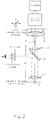
- According to the invention a microscope is provided with a supplementary means for producing a light spot S in the object plane of the microscope objective lens, the means comprising a light source from which a collimated light beam is derived, a focusing lens L1 receiving the collimated beam and a coupling lens L2 disposed between said first lens L1 and the objective lens MO whereby a light spot is produced from said collimated beam in the object plane of the objective lens MO, (i) the focal point F of the focusing lens L1 being in the plane of the image of a specimen in said object plane as obtained through the objective lens MO and the coupling lens L2, (ii) the light beam filling the clear aperture of the objective lens MO without substantial light loss and (iii) the focusing lens L1 being movable in a plane perpendicular to its axis to displace the light spot S in the object plane of the objective lens MO, the parameters of the system being such that the axial ray of light from said light source always passes through the second principal point (i.e. that on the object side) of the objective lens MO.
- The focusing lens L1 may additionally be capable of limited movement parallel to its axis so that the light spot is displaced a short distance from the object plane of the objective lens MO.
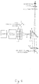
- In a first embodiment the light source is moved together with the focusing lens L1 perpendicularly to said axis. In a second embodiment of the invention, the focusing lens L1 is movable perpendicularly to said axis relatively to the collimated light beam.
- The invention will now be further explained by way of example with reference to the two aforesaid embodiments which are shown in Figures 1 and 2 respectively of the accompanying annotated drawings. Figures 3 and 4 of the drawings show modifications of the Figures 1 and 2 systems respectively.
- In order to efficiently focus light into a small spot one should utilise the whole clear aperture of the lens used for focusing. For example, for the case of a gaussian laser beam the size of the spot will be:

where - λ -
- wavelength of light,
- f -
- focal length of the lens,
- φ -
- beam diameter at the lens.
- A beam narrower than the aperture would not produce a spot of the minimum (i.e. diffraction limited) size. Conversely, a wider beam would result in a loss of light power. The above should be true regardless of the position or the spot, i.e. whether it is displaced away from the optical axis or not. In the present invention the above requirements are met by ensuring that:
- a) the beam is expanded to fill the clear aperture of the objective lens;
- b) the axial ray of light emerging from the light source always passes through the second (i.e. object side) principal point of the objective lens.
- Further, the focal point F of the focusing lens L1 is arranged in the plane of the image of the specimen as obtained through the objective lens MO and the coupling lens L2. This has the effect of adapting a parallel beam of light to the finite conjugate ratio of the majority of microscope objective lenses by making the beam divergent.
- The light produced by a semi-conductor laser can be collimated by means of lenses, prisms or a combination of both into a beam of circular cross-section. Such a beam can have divergence sufficiently low that it results in an additional contribution to the size of the final spot of light produced by the present invention comparable in magnitude or smaller than the size pertaining to formula (1). Thus when the present invention is used in conjunction with a semi-conductor laser and a collimator producing a quasi-parallel beam of sufficiently low divergence the size of the spot of light can be close to or less than 1 µm.
- The optical systems of the two embodiments have the following features:
- 1. The focal point F of the focusing lens L1 as stated above is in, or close to, the plane of the image of the specimen in the objective lens MO and the coupling lens L2. If the lens L1 is a positive one the focal point F is the second (rear) focal point; if it is a negative one the focal point F (imaginary) is the first (front) focal point. In the second embodiment the lens L1 must be positive.
- 2. The laser beam fills the whole aperture of the microscope objective lens MO, irrespectively of the deflection of the beam. This is achieved by a judicious choice of the focal lengths of the lenses used.
- 3. In the first embodiment the second (object side) principal point of the microscope objective lens MO coincides with the second focal point of the coupling lens L2.
- 4. In the second embodiment the focusing lens L1 and the second (object side) principal point of the microscope objective lens MO are in the conjugate planes of the coupling lens L2.
- 5. The mirror M allows viewing the specimen and is such that it reflects a substantial part of the visible light originating from the specimen and transmits a substantial part of the light emitted by the laser.
- 6. In the first embodiment the laser, collimator and focusing lens assembly can be moved as a unit in the plane perpendicular to the optical axis of the said assembly whereby the focused light spot S is moved within the object plane of the microscope by an amount proportional to but generally smaller than the displacement of the said assembly. If desired the said assembly may also be made capable of displacement parallel to the said axis the said displacement resulting in a respective displacement of the said light spot S away from the said object plane.
- 7. In the second embodiment the focusing lens L1 can be displaced in the plane perpendicular to the optical axis of the said lens and possibly it can also be displaced parallel to the said axis the respective displacements having the same influence on the position of the focused light spot S as in point 6 above.
- The formulae for the first embodiment may be derived as follows. It is assumed that all distances are measured between appropriate principal points of the lenses.
- The diameter φ₂ of the laser beam in the plane of the coupling lens L2 is described by:

where: - φ₁ -
- original diameter of the laser beam,
- d -
- distance between the lenses L1 and L2,
- f₁ -
- focal length of the lens L1 (note that f₁ is negative for a negative-power lens).
- The virtual image of the focal point F in the lens L2 is formed at the distance ℓ from the objective lens MO (see Fig. 3). Because the distance between L2 and MO is equal to f₂ the lens equation for the lens L2 takes the form:

- The diameter φ of the beam in the plane of the lens MO is:

- By combining equations (2), (3) and (4) we obtain the expression:

which allows choosing the focal lengths of the lenses given the collimated beam diameter and the diameter φ which is determined by the size of the clear aperture of the objective lens MO. The latter can be calculated with the aid of the approximate formula:

where N and f₃ are, respectively, the numerical aperture and the focal length of the objective lens MO and n is the refractive index of the medium in which the specimen is immersed. It must be remembered that the focal length f₂ determines the distance between the coupling lens L2 and the objective lens MO. Having chosen the focal lengths, one can obtain the distance d between the focusing lens L1 and the coupling lens L2 from formula (2) (note again that f₁ can be either positive or negative, depending on the type of the lens L1). The length ℓ is equal to the object-to-image distance of the microscope (usually 195mm) less the focal length f₃ of the objective lens. - The formulae for the second embodiment may be derived as follows. It is again assumed that all distances are measured between appropriate principal points of the lenses.
- The diameter φ₂ of the laser beam in the plane of the coupling lens L2 is described by the equation:

where: - φ₁ -
- original diameter of the laser beam,
- d -
- distance between the lenses L1 and L2,
- f₁ -
- focal length of the lens L1.
- Because the lenses L1 and MO are in the conjugate planes of the lens L2 the lens equation for the lens L2 can now be written as:

where d' is the distance between the lenses L2 and MO. We also have:

since the virtual image of the focal point F in the lens L2 is formed at thedistance 1 from the objective lens MO. The diameter φ of the beam in the plane of the lens MO is:
By combining equations (7), (8), (9) and (10) we obtain:

Having chosen d' and f₂ one can calculate d from formula (8) and f₁ from formula (9). - In a modification of the present invention shown in Figures 3 and 4 the viewing path and laser beam path have been interchanged as compared with Figures 1 and 2 respectively. Also therefore the mirror M should transmit a substantial part of the visible light originating from the specimen and reflect a substantial part of the light emitted by the laser.
- In a further modification of the above described embodiments the mirror M can be such that it reflects most of the visible light (used for viewing) and transmits most of the laser light (used for producing the light spot) in the case of the embodiments shown in Figures 1 and 2. Again, the reverse should be the case for the embodiments shown in Figures 3 and 4. The above can be accomplished with the aid of an interference filter designed for oblique incidence. Such a filter can be chosen to transmit and reflect only at desired wavelengths or wavelength ranges and thus separate the viewing path from the laser light path more efficiently.
- If a high-power light source producing invisible radiation is used additional protection to the viewer can be afforded by placing a blocking filter between the mirror M and the eyepiece of the microscope.
- Finally, a laser providing a collimated beam can be used rather than a separate collimator being provided.
Claims (5)
- A microscope provided with a supplementary means for producing a light spot in the object plane of the microscope objective lens, characterised in that the means comprises a light source from which a collimated light beam is derived, a lens, referred to hereafter as focusing lens, receiving the collimated beam and a coupling lens disposed between said focusing lens and the objective lens whereby a light spot is produced from said collimated beam in the object plane of the objective lens, (i) the focal point of the focusing lens being in the plane of the image of a specimen in said object plane as obtained through the objective lens and the coupling lens, (ii) the light beam filling the clear aperture of the objective lens without substantial light loss and (iii) the focusing lens being movable in a plane perpendicular to its axis to displace the light spot in the object plane of the objective lens, the parameters of the system being such that the axial ray of light from said light source always passes through the second principal point (i.e that on the object side) of the objective lens.
- A microscope according to claim 1, characterised in that the focusing lens and the light source are movable together perpendicularly to said axis.
- A microscope according to claim 1 characterised in that the focusing lens and the second (object side) principal point of the microscope objective lens are in the conjugate planes of the coupling lens.
- A microscope according to claim 2, characterised in that the second (object side) principal point of the microscope objective lens coincides with the second focal point of the coupling lens.
- A microscope according to any one of claims 1 to 4, characterised in that said light source is a laser source and a light-splitting mirror characterised by wavelength-dependent reflectance is disposed between the coupling lens and the objective lens so that the laser light and the visible light from a specimen in the object plane have a common path between the mirror and the objective lens and the majority of one of said lights is transmitted by the mirror while the other light is reflected by the mirror.
Applications Claiming Priority (1)
| Application Number | Priority Date | Filing Date | Title |
|---|---|---|---|
| GB8910307A GB2231681B (en) | 1989-05-05 | 1989-05-05 | Optical microscopes |
Publications (1)
| Publication Number | Publication Date |
|---|---|
| EP0486732A1 true EP0486732A1 (en) | 1992-05-27 |
Family
ID=10656248
Family Applications (1)
| Application Number | Title | Priority Date | Filing Date |
|---|---|---|---|
| EP90312592A Ceased EP0486732A1 (en) | 1989-05-05 | 1990-11-20 | Optical microscopes |
Country Status (3)
| Country | Link |
|---|---|
| US (1) | US5225929A (en) |
| EP (1) | EP0486732A1 (en) |
| GB (1) | GB2231681B (en) |
Cited By (1)
| Publication number | Priority date | Publication date | Assignee | Title |
|---|---|---|---|---|
| WO2001035150A1 (en) * | 1999-11-10 | 2001-05-17 | Carl Zeiss Jena Gmbh | System for introducing optical tweezers and/or a treatment beam into a microscope |
Families Citing this family (5)
| Publication number | Priority date | Publication date | Assignee | Title |
|---|---|---|---|---|
| DE69729659T2 (en) * | 1996-02-28 | 2005-06-23 | Johnson, Kenneth C., Santa Clara | MIKROLINSEN RASTER DEVICE FOR MICROLITHOGRAPHY AND FOR CONFOCUS MICROSCOPY WITH LARGE RECORDING FIELD |
| US6251101B1 (en) | 1998-06-26 | 2001-06-26 | Visx, Incorporated | Surgical laser system microscope with separated ocular and objective lenses |
| US6898006B2 (en) * | 2001-12-26 | 2005-05-24 | Olympus Optical Co., Ltd. | Microscope |
| US7282729B2 (en) * | 2003-08-20 | 2007-10-16 | Xyratex Technology Limited | Fabry-Perot resonator apparatus and method for observing low reflectivity surfaces |
| EP3538941A4 (en) | 2016-11-10 | 2020-06-17 | The Trustees of Columbia University in the City of New York | Rapid high-resolution imaging methods for large samples |
Citations (3)
| Publication number | Priority date | Publication date | Assignee | Title |
|---|---|---|---|---|
| US3460880A (en) * | 1964-12-18 | 1969-08-12 | Beckman Instruments Inc | Point illumination and scanning mechanism for microscopes |
| DE2443167A1 (en) * | 1974-09-10 | 1976-03-25 | Strahlen Umweltforsch Gmbh | Focusing mechanism esp for microscopes - can be added to vertical illumination instruments |
| US4523799A (en) * | 1981-12-04 | 1985-06-18 | Agence Nationale De Volorisation De La Recherche (Anvar) | Device optimizing the coupling of two optical systems for the observation and analysis of objects |
Family Cites Families (3)
| Publication number | Priority date | Publication date | Assignee | Title |
|---|---|---|---|---|
| JPS52111295A (en) * | 1976-03-15 | 1977-09-17 | Mochida Pharm Co Ltd | Operational laser optical device under microscope |
| DE2843287A1 (en) * | 1977-10-05 | 1979-04-19 | Canon Kk | EYE EXAMINATION INSTRUMENT |
| DE3006657A1 (en) * | 1980-02-22 | 1981-09-03 | Ernst Leitz Wetzlar Gmbh, 6330 Wetzlar | COMPARATIVE MACROSCOPE OR -MICROSCOPE |
-
1989
- 1989-05-05 GB GB8910307A patent/GB2231681B/en not_active Expired - Fee Related
-
1990
- 1990-11-20 EP EP90312592A patent/EP0486732A1/en not_active Ceased
-
1991
- 1991-11-18 US US07/793,631 patent/US5225929A/en not_active Expired - Fee Related
Patent Citations (3)
| Publication number | Priority date | Publication date | Assignee | Title |
|---|---|---|---|---|
| US3460880A (en) * | 1964-12-18 | 1969-08-12 | Beckman Instruments Inc | Point illumination and scanning mechanism for microscopes |
| DE2443167A1 (en) * | 1974-09-10 | 1976-03-25 | Strahlen Umweltforsch Gmbh | Focusing mechanism esp for microscopes - can be added to vertical illumination instruments |
| US4523799A (en) * | 1981-12-04 | 1985-06-18 | Agence Nationale De Volorisation De La Recherche (Anvar) | Device optimizing the coupling of two optical systems for the observation and analysis of objects |
Cited By (3)
| Publication number | Priority date | Publication date | Assignee | Title |
|---|---|---|---|---|
| WO2001035150A1 (en) * | 1999-11-10 | 2001-05-17 | Carl Zeiss Jena Gmbh | System for introducing optical tweezers and/or a treatment beam into a microscope |
| JP2003514252A (en) * | 1999-11-10 | 2003-04-15 | カール ツァイス イエナ ゲゼルシャフト ミット ベシュレンクテル ハフツング | Device for connecting optical tweezers and / or processing beam into microscope |
| US6850363B1 (en) | 1999-11-10 | 2005-02-01 | Carl Zeiss Jena Gmbh | System for introducing optical tweezers and/or a treatment beam into a laser scanning microscope |
Also Published As
| Publication number | Publication date |
|---|---|
| GB2231681B (en) | 1993-04-21 |
| GB8910307D0 (en) | 1989-06-21 |
| US5225929A (en) | 1993-07-06 |
| GB2231681A (en) | 1990-11-21 |
Similar Documents
| Publication | Publication Date | Title |
|---|---|---|
| US5288987A (en) | Autofocusing arrangement for a stereomicroscope which permits automatic focusing on objects on which reflections occur | |
| CA1325537C (en) | Confocal microscope | |
| EP0038563A2 (en) | Optical system with high coupling efficiency, in particular for attenuation measurement apparatuses employing the back-scattering technique | |
| JPS58217909A (en) | Apparatus adapted to allow automatic focusing on object being observed with optical apparatus | |
| US6204955B1 (en) | Apparatus for dynamic control of light direction in a broad field of view | |
| JPH0748091B2 (en) | Prism system for stereo microscope and stereo microscope | |
| CA1109142A (en) | Passive optical range simulator device | |
| US4383741A (en) | Binocular night telescope | |
| GB2220501A (en) | Coupling waveguides using transverse cylindrical lenses | |
| US7167321B1 (en) | Optical systems and methods employing adjacent rotating cylindrical lenses | |
| WO2008155241A3 (en) | Device for machining a workpiece by means of a laser beam | |
| JPH03123313A (en) | Optical attenuator | |
| EP0072652A1 (en) | Variable stereomicroscope | |
| EP0486732A1 (en) | Optical microscopes | |
| EP0278929B1 (en) | Alignment means for a light source emitting invisible laser light | |
| KR970703540A (en) | Optical beam-splitting element | |
| US5570189A (en) | Split-field pupil plane determination apparatus | |
| JPS61500395A (en) | Neodymium laser device suitable for ophthalmological procedures | |
| US5130533A (en) | Device for measuring backscattered radiation using a frequency selective element | |
| US4917457A (en) | Beam separating prism | |
| EP0062429A1 (en) | Optical coupling devices for optical fibres | |
| US4281905A (en) | Magneto-optic light deflector beam recombination apparatus | |
| GB2147716A (en) | Adapter for illumination or laser radiation for surgical microscopes | |
| Sutter | Extended sources—concepts and potential hazards | |
| JPS6223007A (en) | Method and apparatus for measuring coupling loss of single mode optical fiber |
Legal Events
| Date | Code | Title | Description |
|---|---|---|---|
| PUAI | Public reference made under article 153(3) epc to a published international application that has entered the european phase |
Free format text: ORIGINAL CODE: 0009012 |
|
| AK | Designated contracting states |
Kind code of ref document: A1 Designated state(s): AT BE CH DE DK ES FR GB GR IT LI LU NL SE |
|
| RBV | Designated contracting states (corrected) |
Designated state(s): CH DE FR GB LI |
|
| 17P | Request for examination filed |
Effective date: 19921125 |
|
| 17Q | First examination report despatched |
Effective date: 19940808 |
|
| STAA | Information on the status of an ep patent application or granted ep patent |
Free format text: STATUS: THE APPLICATION HAS BEEN REFUSED |
|
| 18R | Application refused |
Effective date: 19960120 |