EP0486678B1 - Rasierapparat - Google Patents
Rasierapparat Download PDFInfo
- Publication number
- EP0486678B1 EP0486678B1 EP91912634A EP91912634A EP0486678B1 EP 0486678 B1 EP0486678 B1 EP 0486678B1 EP 91912634 A EP91912634 A EP 91912634A EP 91912634 A EP91912634 A EP 91912634A EP 0486678 B1 EP0486678 B1 EP 0486678B1
- Authority
- EP
- European Patent Office
- Prior art keywords
- blade
- frame
- guard
- shaving
- safety razor
- Prior art date
- Legal status (The legal status is an assumption and is not a legal conclusion. Google has not performed a legal analysis and makes no representation as to the accuracy of the status listed.)
- Expired - Lifetime
Links
Images


Classifications
-
- B—PERFORMING OPERATIONS; TRANSPORTING
- B26—HAND CUTTING TOOLS; CUTTING; SEVERING
- B26B—HAND-HELD CUTTING TOOLS NOT OTHERWISE PROVIDED FOR
- B26B21/00—Razors of the open or knife type; Safety razors or other shaving implements of the planing type; Hair-trimming devices involving a razor-blade; Equipment therefor
- B26B21/08—Razors of the open or knife type; Safety razors or other shaving implements of the planing type; Hair-trimming devices involving a razor-blade; Equipment therefor involving changeable blades
- B26B21/14—Safety razors with one or more blades arranged transversely to the handle
- B26B21/22—Safety razors with one or more blades arranged transversely to the handle involving several blades to be used simultaneously
- B26B21/222—Safety razors with one or more blades arranged transversely to the handle involving several blades to be used simultaneously with the blades moulded into, or attached to, a changeable unit
- B26B21/227—Safety razors with one or more blades arranged transversely to the handle involving several blades to be used simultaneously with the blades moulded into, or attached to, a changeable unit with blades being resiliently mounted in the changeable unit
-
- B—PERFORMING OPERATIONS; TRANSPORTING
- B26—HAND CUTTING TOOLS; CUTTING; SEVERING
- B26B—HAND-HELD CUTTING TOOLS NOT OTHERWISE PROVIDED FOR
- B26B21/00—Razors of the open or knife type; Safety razors or other shaving implements of the planing type; Hair-trimming devices involving a razor-blade; Equipment therefor
- B26B21/40—Details or accessories
- B26B21/4012—Housing details, e.g. for cartridges
- B26B21/4018—Guard elements
-
- B—PERFORMING OPERATIONS; TRANSPORTING
- B26—HAND CUTTING TOOLS; CUTTING; SEVERING
- B26B—HAND-HELD CUTTING TOOLS NOT OTHERWISE PROVIDED FOR
- B26B21/00—Razors of the open or knife type; Safety razors or other shaving implements of the planing type; Hair-trimming devices involving a razor-blade; Equipment therefor
- B26B21/40—Details or accessories
- B26B21/4068—Mounting devices; Manufacture of razors or cartridges
Definitions
- This invention relates to safety razors of the form comprising a frame supporting one or more blade members in a manner permitting movement of the blade members, against resilient restoring forces, in response to forces encountered in use.
- a well known example of a safety razor of this general form is disclosed in US-A-4492025 in which the individual blade members of a tandem pair are displaceable against the action of restoring springs in directions perpendicular to a notional plane tangent to fixed guard and cap surfaces before and behind the blade edges so as to reduce the exposure of the blade edges in response to increased forces applied to the edges by the skin in use, whether due to changing skin contours or increased pressures applied by the user's hand or a combination of both.
- the present invention is mainly characterized in that the (or each) blade member is movably mounted in the frame in such a manner that the shaving angle of the (or each) blade is reduced when in use the razor encounters increased drag forces, that is to say forces acting substantially parallel with the direction of shaving.
- shaving angle is used herein in its normal sense in the art to indicate the acute angle formed between the median plane of a blade member and a notional plane tangent to the skin engaging members immediately ahead of and behind the blade member. In the case of a single blade razor, these would be the guard and the cap members. In a tandem edged razor, the respective skin engaging members are constituted by the guard and the second blade edge, or the first blade edge and the cap.
- the razor has a guard member which is displaceable relative to the frame and whose rearward displacement, against the action of resilient restoring forces, is transmitted to the blade members to cause them to pivot or hinge about axes parallel with the blade edges.
- the guard member may be constrained to move only in directions parallel to the shaving direction or it may be mounted for compound movements in these directions and perpendicular thereto to take account of drag forces and of forces normal thereto.
- a principle factor in the magnitude of drag forces is the direction of the grain of the beard, which is different in different regions of the face.
- the hair on the cheeks emerges from the skin at an angle thereto, sloping downwardly.
- a "downstroke” in these regions is essentially “with the grain”.
- Many men prefer to shave with downstrokes and with “upstrokes” ("against the grain") to obtain a closer shave.
- Greater drag forces are experienced by the razor in these strokes against the grain.
- facial skin shows a greater tendency to bulge when a razor is moved up the face, particularly over the cheeks and this also tends to increase the drag forces experienced by the razor.
- the shaving angle of blades in modern razors is normally pre-set in manufacture at about 22°-25°, which is found to provide an optimum angle of attack between the blade edge and the hairs for efficient cutting, but is necessarily a compromise, baring in mind that most hairs do not emerge from the skin at right angles thereto.
- a relatively high shaving angle is desirable for the blades
- a relatively shallower shaving angle is desirable for the blades.
- the conflicting requirements of these different shaving conditions must be balanced and a compromise accepted.
- French Patent 2,457,155 discloses a two-blade razor head in which both blades are pivotally mounted so that the blade angles can be changed in accordance with forces produced during shaving.
- the blades move in opposite directions sot that the shaving angle of both blades cannot be decreased.
- movement of each blade is in a direction which reduces the shaving the shaving angle of each blade in response to an increase in drag forces acting parallel to the direction of shaving.
- a safety razor comprising a frame supporting one or more blade members and a guard in a manner permitting perpendicular movement of the blade members, relative to the frame, against resilient restoring forces, in response to the forces encountered by the razor in use, characterized in that the or each blade member is provided with pivotal mounting means supported in the said frame for angular movement about an axis parallel with the blade edge, in a direction which reduces the shaving angle of the blade member in response to an increase in drag forces acting parallel with the direction of shaving to move the or each blade member or guard relative to the frame.
- a razor according to the invention can have blade members arranged so that they are biased to positions in which the blade edges have a shaving angle which is the optimum when drag forces are low, i.e. when shaving with the grain, but the blades adapt in response to large drag forces being applied so that the shaving angels of the blades are reduced to suit those conditions when shaving against the grain.
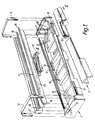
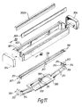
- the razor head shown in Figs. 1 and 2 is in the form of a replaceable blade cartridge comprising a generally rectangular base frame 1 supporting a cap 2, a guard 3, a pair of blade members 4 and a pair of retaining clips 6.
- the frame 1 is formed in its end walls with slots 7 to receive and guide the blade members and, beneath the slots and in longitudinal alignment therewith, integral spring fingers 8 inclined upwardly to free ends which act on the blade members to urge the blade members upwardly in their slots.
- the slots 7 are substantially upright, i.e. perpendicular to the plane in which the blade edges lie in their rest position, whereas in the modified construction illustrated in Fig. 2 the slots are inclined downwardly and rearwardly with respect to said plane, the effect of which is explained below.
- the slots are provided to enable vertical movement of the blade member, but are not essential for the purposes of the present application.
- the blade members are mounted in the frame for pivotal movement only, there being no slots in the frame or any other means providing for vertical movement of the blade members.
- the cap 2 is retained fixedly in a recess 9 at the rear longitudinal wall of the frame.
- the front wall of the frame is formed integrally with spring fingers or bars 11 to which the guard 3 is attached locally, as best seen in Fig. 2, so that the guard is resiliently displaceable, by flexing of the bars 11, both rearwardly and downwardly relative to the frame.
- the rear, inner face of the guard 3 carries a rearwardly projecting nib or bumper 12 for cooperation with the blade members, as described below.
- the blade members each consist of an angular metallic support 13 of substantially inverted L-shape and having secured to each end a pivot pin 14 which is received in a respective end wail slot 7.
- a narrow blade strip 16 is attached to the inclined upper leg of the support 13, in known manner.
- the spring fingers 8 act on the underside of those parts of the supports carrying the blade strips and urge the blade members upwardly, so that the extreme ends of the blade strips 16 bear against the clips 6, which thus limit their upward movement.
- the supports 13 are fitted with generally u-shaped clips on which are provided abutments, or blade bumpers 17, aligned with the guard bumper 12.
- Integral springs 10 formed at the rear of the frame 1 bear on the rear blade support 13, tending to pivot the member in a clockwise direction as seen in Figure 2, this pivotal movement being limited by a stop 18 formed on the frame.
- the rear blade bumper 17 bears against the forward blade bumper, to urge the forward blade against its own stop 18 and against the guard bumper 12.
- the rear faces of the stops 18 against which the blade supports abut are parallel to the slots 7 and hence are substantially upright for the razor head of Fig. 1 and in the case of the modified razor head of Figure 2 are inclined downwardly and rearwardly.
- the abutment face of the bumper 12 is substantially parallel to the slots 7 and the rear faces of the stops 18.
- the blade members are free to move along the slots 7, against the resilient restoring forces of the spring fingers 8, to permit the blades to conform closely to the varying contours of the skin being shaved.
- the razor operates in the manner of the razor described in US-A-4492025. There is no pivoting of the blade members due to the parallel relationship between the slots 7 and the abutment faces of the stops 18 and the bumper 12.
- guard bumper 12 will slide over the blade bumpers 17. Again the blades are able to move bodily along the slots 7, but there is no pivotal movement as they are maintained in abutment with and restrained by the stops 18.
- the guard will also experience drag forces, and if these are sufficient to overcome the spring forces applied to the guard by its supporting bars 11 and by the springs 10 integral with the frame and bearing forwardly on the guard through the blade supports and the bumpers 17, 12, the guard will also be displaced rearwardly. This rearward motion of the guard will be transmitted through the bumpers 12 and 17 to the lower legs of the blade supports to cause them to move away the stops 18 and hence cause the blade members to pivot anti-clockwise about the axes of pins 14 and thus reduce the shaving angles of the blade strips. The amount by which the shaving angle is reduced is dependent on the rearward displacement of the guard and hence the drag forces
- the slots 7 are vertical, in which case rearward movement of the guard will cause pivoting of the blade members.
- the guard could be constrained to move only forwardly and rearwardly, i.e. parallel with the shaving direction.
- the surface of the bumper 12 on the guard 3, which bears against the bumper 17 on the front blade member, is inclined to the vertical so that pivotal adjustment of the blade members is dependent upon the direction in which the guard is displaced from its rest position.
- the particular angle at which the bumper surface is inclined is not itself crucial and may vary within a wide range as the direction in which the guard moves under an applied force will depend not only the direction of that force, but also other factors such as the relative strengths of the spring forces acting on the guard member to oppose rearward movement and normal movement.
- the inclination selected will be influenced by the desired change in blade shaving angle in response to guard member movement.
- the guard member In use the guard member is subjected, not only to drag forces (parallel with the direction of shaving) but also to "normal" forces perpendicular thereto, so that in practice it experiences a resultant force inclined downwardly and rearwardly. Since both the drag and normal forces vary during shaving, the angle of the resultant force will also vary but an optimum "threshold" angle can be determined empirically. When the resultant force acts at an angle in excess of the threshold angle, indicating that the drag forces are high relative to the normal forces, the blades are caused to pivot to reduce their shaving angles by appropriate choice of the inclination of the abutment surface of the bumper 12 on the guard member.
- the angle at which the rear surface of the bumper is inclined to the normal will be substantially the same as the selected threshold angle of the resultant force, and as shown in Figure 2 this angle is about 30°, the slight convex curvature shown allowing for torsional deflection of the guard support bars 11.
- the slots 7 are arranged to be inclined at a corresponding angle so that downward deflection of the forward blade member from its rest position does not result in pivotal movement of this blade member due to the influence of the inclined rear surface of the bumper 12.
- the abutment faces of the stops 18 are also arranged at the same angle, i.e. parallel to the slots 7.
- the resultant force angle varies continuously.
- the guard bumper 12 separates from the forward blade bumper 17, and there is no pivotal movement of the blade members to change the shaving angle.
- the resultant force angle coincides with the angle of the slots 7, the guard bumper slides along the forward blade bumper 17 without exerting any rearward pressure to it and again there is no pivotal adjustment of the blade members.
- the resultant force is at an angle which exceeds the threshold angle, rearward movement of the guard is transmitted to the blade members to cause them to pivot about the axes of the pins 14 and the shaving angles of the blades to be reduced in proportion to the actual resultant force angle.
- the blade members may be arranged to have, in their rest position, a shaving angle which is optimally suited to shaving conditions when low drag forces are experienced, such as when shaving with the grain.
- a shaving angle which is optimally suited to shaving conditions when low drag forces are experienced, such as when shaving with the grain.
- the blade members will automatically adjust to reduce their shaving angles to suit these conditions. Thus the need to compromise by choosing one shaving angle for all conditions is avoided.
- Fig. 3 is similar in construction and operation to that of Fig. 2, but the guard is modified. More particularly, the guard here comprises a displaceable forward section 3A, and a fixed, rear section 3B.
- the forward section 3A is displaceable, in the manner described above, i.e. rearwardly under drag forces and downwardly under normal forces, and includes the bumper 12 with an abutment face parallel to the slots 7.
- the narrow, rear section 3B is fixed to the frame in order to preserve a minimum span between itself and the forward blade.
- the rear section 3B could alternatively be constrained for vertical ("normal") movement and urged upwardly by spring means.
- the bumpers 17 fitted to the blade supports are shown to be of different form and comprise pegs or plates fastened to the supports, but they function in exactly the same way as the bumpers 17 of the Figure 2 razor head.
- the forward section 3A of the guard is displaced in a direction inclined at an angle greater than that at which the slots 7, and the operative faces of the bumper 12 and the stops 18 are inclined to the normal, the blade members are caused to pivot to reduce their shaving angles.
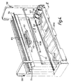
- Figs. 4, 5 and 6 illustrate a further embodiment of the invention, generally similar to that of Fig. 2, but having a "two part" guard, modified bumpers and re-positioned pivot pins.
- the guard comprises a fixed forward portion 103A integral with the frame 101 and a rear portion 103B which is displaceable both rearwardly and downwardly from the position illustrated in Fig. 5 against the action of resilient sections 111 formed integrally with the portion 103B and corresponding in function to the bars 11 of Figs. 1 and 2.
- the guard bumper 112 is shaped so that in the rest position shown in Figure 5 it makes face-to-face contact with the bumper 117 of the leading blade unit, these bumper faces being essentially parallel with slots 107 in the end walls of the frame and in which the pins 114 of the blade members engage.
- the stops 118 serve the same purpose as the stops 18 in Figures 2 and 3, and likewise have abutment faces parallel to the slots 107.
- pivot pins 114 are secured to the blade units 104 above the blade platforms so as to be engageable with the underside of the retaining clips 106.
- the springs 108 bear upwardly on the undersides of the blade platforms 113, between the pins 114 and the blade edges, which also engage the clip so that the units are biassed into the stable position of rest seen in Figure 5.
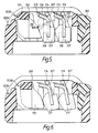
- FIG. 5 shows the parts in their normal position of rest
- Figure 6 shows them deflected as a consequence of movement of the guard portion 103B both downwardly and rearwardly, i.e., under normal and drag forces.
- displacement of the guard portion 103B in a direction inclined to the normal at an angle greater than that at which the slots 107 and the abutment faces of the stops 118 and the bumper 112 are inclined to the normal results in the blade members being pivoted about the axes of the pins 114 to reduce the shaving angle of the blades, as clearly depicted in Fig. 6.
- the blade members are of a completely different construction and instead of pivoting about fixed axes defined by pins they flex or hinge about axes parallel with their blade edges thanks to the flexure of spring arms integral with the blades.
- Figure 7 is an end view and Figure 8 a scrap perspective view of one end portion of a twin blade unit comprising two separate blade members 200A and 200B having respective sharpened cutting edges 201A, 201B, formed on blade strip portions 205A, 205B, and downturned legs 202A, 202B which serve to stiffen the strip portions 205A, 205B.
- the rear margins 203A, 203B of the blade members are superposed and directly secured to each other, as by spot welding, the rear margins remaining connected to the blade strips only by spring arms 209A, 209B at opposite ends of each unit.
- the two members are generally planar in their "free" condition, except for the legs 202A/B being turned down out of the main plane, but the blade strip portions 205A/B can be separated from each other by flexure of the arms 209A/B.
- Figure 7 also shows an optional strip 205 of lubricating material retained by clips 204.
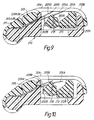
- FIG. 9 the above described twin blade unit is shown mounted in a razor frame 210 having a hinging cap portion 211 incorporating end clips 206 (like the clips 6 shown in Figure 1).
- the cap portion is closed, as shown in Figure 9, the rear margins 203A/B are turned down and clamped, the strip portions 205A/B being retained at their sharpened edges by the clips 206 against which they are spring loaded by the strain energy in the spring arms 209A/B.
- the razor also comprises a spring loaded displaceable guard portion 212B displaceable rearwardly and downwardly in use in the same manner as the guard portion 103B in Figures 4, 5 and 6, and a forward, fixed guard portion 212A corresponding to the portion 103A in Figures 5 and 6.
- the guard portion 212B has a rearwardly extending bumper 213 engageable with a bumper 218 attached to the leg 202A of the leading blade member and engageable in turn with the leg 202B of the rear blade member.
- the guard portion 212B if the guard portion 212B is displaced rearwardly, due to encountering high drag forces, its bumper 213 engages the bumper 218 which in turn engages the leg 202B, causing both legs to be tilted rearwardly with concomitant flexure of the spring arms 209A/B and consequent deflection or angling of the blade strip portions 205A/B in a clockwise sense as viewed in Figs. 9 and 10, i.e. so that the blade edges move downwardly and forwardly, to reduce their respective shaving angles.
- the abutment face of the bumper 213 is essentially vertical so that downward displacement of the guard portion 212B does not produce any movement of the blades. It could alternatively be inclined as in the razor heads of Figs. 2-6 so that the movement of the blades to reduce their shaving angles is dependent upon the direction in which the guard portion 212B is displaced under the resultant of the drag and normal forces.
- drag forces are essentially detected by a skin engaging guard member which is rearwardly displaceable, against the action of a resilient restoring force, and this motion is transmitted to the blades to effect a reduction in their shaving angle.
- the guard is (or may be) rigid and it is drag forces applied to the blade edges which will, if sufficiently high, effect a reduction in shaving angle.
- this is achieved by virtue of the fact that blade members are mounted for pivotal movement about axes parallel with the blade edges and spaced above the blade strips, "above” being used in the sense of higher than the blades when the razor is in an upright attitude with the skin engaging surfaces uppermost.
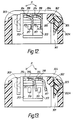
- the razor head illustrated is in the form of a replaceable blade cartridge comprising a generally rectangular base frame 301 including a cap 302, a guard 303, opposed end cheeks 304, a moulded blade carrier 306 and a pair of blade members 307.
- the guard 303 is located in guide slots in the ends of frame 301 and is retained by the cheeks 304 in known manner.
- a lubricating strip 302A is secured in a slot in the frame by shoulders 305.
- the blade carrier 306 is of unitary moulded construction comprising a central frame 308 across which extend oppositely directed spring arms 309 having upwardly projecting abutments 311 at their free, inner ends. At each of its ends, the frame has integrally formed with it a pair of outwardly and upwardly extending spring fingers 312 carrying at their outer ends respective support blocks 313, each formed on its inner face with an arcuate groove 314 and a blade stop 316.
- Each blade comprises an angular metallic blade support 317 having secured to its upper leg a narrow blade strip 318 with a sharpened, longitudinal cutting edge.
- the support is additionally formed at each end with an integral male bearing member 319 of arcuate form.
- the carrier In the assembled cartridge, the carrier is firmly located in the frame 301 and the blade members are supported by their bearing members 319 being received in the grooves 314 of the blocks 313.
- the bearing members 319 in conjunction with the arcuate slots in the blocks form shell bearings to guide the blade members for pivotal movement.
- the abutments 311 engage the respective blade supports 317 from the rear, urging the blade members in a clockwise direction, as viewed in Figures 12 and 13, to one extreme pivotal position of adjustment about the imaginary pivot axes 'P' which coincide with the centres of curvature of the arcuate grooves 314 and bearing members 319. In this position which is shown in Figure 12, the blade supports abut the stops 316.
- the blade members In use of the razor, when the individual blades experience drag forces sufficient to overcome the biasing forces exerted on them by the spring arms 309, the blade members are moved rearwardly and as a result of the arcuate form of the bearing members 319 and the grooves the blade members are displaced in an anti-clockwise direction about the pivot axes P so as to reduce the shaving angles of the blades. In the extreme case shown in Figure 13, this movement is limited by abutment of the blade bearings 319 with the ends of the arcuate slots 314. In the normal or starting attitude of the blade members, the shaving angle of each blade is set at about 28°, and in the opposite extreme position it is reduced to 15°.
- the two blades can assume different shaving angles, in accordance with different drag forces applied to them.
- the shaving angles of the blades are reduced in response to the presence of relatively high drag forces, whether caused by the fact that the blades are working against the local grain of the hair, or by local bulging of the skin, or both, so as to optimise the angle of attack of the blades against the hairs and minimise damage to the skin in that locality.
- the blade members are also able to move, independently of each other, in directions perpendicular to the shaving directions under the action of normal forces experienced in use, principally arising from the pressure applied by the user in holding the razor against the skin. These movements are accommodated by displacement of the individual blocks 313 against the resilient restoring forces of the spring fingers 312.
- each of the razor heads may be permanently associated with a handle, instead of constituting an exchangeable cartridge.
- One blade member may be employed, or three or more.
Claims (11)
- Sicherheitsrasierer umfassend einen Rahmen, auf dem ein oder mehrere Klingenelemente gelagert sind, und eine Schutzvorrichtung, die eine senkrechte Bewegung der Klingenelemente in bezug auf den Rahmen gegen elastische Rückstellkräfte erlaubt, die bei den im Gebrauch auf den Rasierer wirkenden Kräften auftreten, dadurch gekennzeichnet, daß das bzw. jedes Klingenelement (16, 116, 205A/B, 318) mit einer drehbaren Halterung (14, 205A/B, 114, 319) versehen ist, die in dem Rahmen (1, 101, 210, 301) so gelagert ist, daß sie eine Winkelbewegung um eine zur Klingenkante parallele Achse ausführen kann in eine Richtung, die den Rasierwinkel des Klingenelements entsprechend einer Zunahme der parallel zur Rasierrichtung wirkenden Widerstandskräfte verkleinert, so daß das bzw. jedes Klingenelement oder die Schutzvorrichtung in bezug auf den Rahmen bewegt wird.
- Sicherheitsrasierer nach Anspruch 1, dadurch gekennzeichnet, daß die Schutzvorrichtung (3; 3A; 103B; 212B) so in dem Rahmen gelagert ist, daß sie in bezug auf den Rahmen gegen die Wirkung der elastischen Rückstellkräfte nach hinten verschoben werden kann, und daß die Verschiebung auf das (bzw. jedes) Klingenelement (4; 104; 205A/B) übertragen wird, um seinen Rasierwinkel zu verkleinern.
- Sicherheitsrasierer nach Anspruch 1 oder 2, bei dem die drehbare Halterung Drehstifte (14, 114) an jedem Ende des (bzw. eines jeden) Klingenelements (4, 104) umfaßt, die in zusammenwirkenden Ausnehmungen (97, 107) in den Stirnwänden des Rahmens (1, 101) aufgenommen sind.
- Sicherheitsrasierer nach Anspruch 3, dadurch gekennzeichnet, daß die Ausnehmungen durch langgestreckte Schlitze (7, 107) gebildet werden, wobei die Schlitze im wesentlichen quer zu einer gedachten Ebene tangential zu den jeweiligen hautberührenden Flächen (2, 3; 102, 103) des Rasierers verlaufen, und daß das (bzw. jedes) Klingenelement durch die elastische Einrichtung (8; 108) nach oben, aus dem Rahmen heraus vorgespannt ist.
- Sicherheitsrasierer nach Anspruch 4, dadurch gekennzeichnet, daß die Schlitze (7; 107) sich in dem Rahmen (1; 101) nach unten und hinten erstrecken.
- Sicherheitsrasierer nach Anspruch 2, dadurch gekennzeichnet, daß die Schutzvorrichtung (3; 103B; 212B) aufgrund der Einwirkung von Normalkräften senkrecht zu den Widerstandskräften ebenfalls nach unten in bezug auf den Rahmen verschiebbar ist, und daß Verschiebungen der Schutzvorrichtung nur dann auf das (bzw. jedes) Klingenelement übertragen werden, wenn die Resultierende der Widerstandskraft und der Normalkraft bewirkt, daß die Schutzvorrichtung längs einer Wirkungslinie verschoben wird, die größer ist als ein vorbestimmter Winkelschwellenwert.
- Sicherheitsrasierer nach Anspruch 2, dadurch gekennzeichnet, daß die Schutzvorrichtung sich nur parallel zur Rasierrichtung bewegen kann.
- Sicherheitsrasierer nach einem der vorhergehenden Ansprüche, umfassend mindestens zwei Klingenelemente (4), von denen jedes eine Halterung (13) in der Form eines umgekehrten "L" umfaßt, an dessen oberem Schenkel ein Klingenstreifen (16) befestigt ist, wobei die Halterungen nach unten ragende Schenkel aufweisen, die aneinander anstoßen, so daß die Winkelbewegung eines Klingenelements direkt auf das andere übertragen wird.
- Sicherheitsrasierer nach Anspruch 2, 6 oder 7, dadurch gekennzeichnet, daß das (bzw. jedes) Klingenelement (200A/B) einen Klingenstreifenabschnitt (205A/B) umfaßt, der einstückig mit Federarmen (209A/B) ausgebildet ist, die den Klingenstreifenabschnitt (205A/B) in dem Rahmen (210, 211) lagern, um eine Schwenkbewegung um eine Achse parallel zur Klingenkante (201A/B) entsprechend einer Rückwärtsbewegung der Schutzvorrichtung (212B) zu ermöglichen.
- Sicherheitsrasierer nach einem der vorhergehenden Ansprüche, dadurch gekennzeichnet, daß das (bzw. jedes) Klingenelement (307) in dem Rahmen (301, 306) in Schalenlagern (314, 319) gelagert ist, um eine Winkelverschiebung um eine feste imaginäre Drehachse (P) parallel zur Klingenkante (317) zu ermöglichen, und so positioniert ist, daß die auf die Klingenkante wirkenden Widerstandskräfte bewirken, daß sich das Klingenelement um diese Achse dreht, so daß der Rasierwinkel kleiner wird.
- Sicherheitsrasierer nach Anspruch 10, dadurch gekennzeichnet, daß zwei Klingenelemente (307) in einem Klingenträger (306) gelagert sind, der jeweils einstückige Federn (309) umfaßt, die die Klingenelemente in eine äußerste Position drücken, in der die Rasierwinkel einen Maximalwert haben, und der außerdem federgelagerte Auflageblöcke (313) umfaßt, die Schalenlager (314) besitzen, in denen die Klingenelemente gelagert sind, wobei der Klingenträger wiederum in dem Rahmen (301) gelagert ist.
Applications Claiming Priority (5)
| Application Number | Priority Date | Filing Date | Title |
|---|---|---|---|
| GB9012979 | 1990-06-11 | ||
| GB909012979A GB9012979D0 (en) | 1990-06-11 | 1990-06-11 | Safety razors |
| GB909015898A GB9015898D0 (en) | 1990-07-19 | 1990-07-19 | Safety razors |
| GB9015898 | 1990-07-19 | ||
| PCT/US1991/003752 WO1991019597A1 (en) | 1990-06-11 | 1991-05-28 | Razor |
Publications (3)
| Publication Number | Publication Date |
|---|---|
| EP0486678A1 EP0486678A1 (de) | 1992-05-27 |
| EP0486678A4 EP0486678A4 (en) | 1992-11-11 |
| EP0486678B1 true EP0486678B1 (de) | 1996-07-17 |
Family
ID=26297187
Family Applications (1)
| Application Number | Title | Priority Date | Filing Date |
|---|---|---|---|
| EP91912634A Expired - Lifetime EP0486678B1 (de) | 1990-06-11 | 1991-05-28 | Rasierapparat |
Country Status (26)
| Country | Link |
|---|---|
| US (1) | US5224267A (de) |
| EP (1) | EP0486678B1 (de) |
| JP (1) | JP3414730B2 (de) |
| KR (1) | KR920702274A (de) |
| CN (1) | CN1033011C (de) |
| AT (1) | ATE140415T1 (de) |
| AU (1) | AU647812B2 (de) |
| BR (1) | BR9105786A (de) |
| CA (1) | CA2063993C (de) |
| CS (1) | CS178991A3 (de) |
| DE (1) | DE69120900T2 (de) |
| DK (1) | DK0486678T3 (de) |
| EG (1) | EG19212A (de) |
| ES (1) | ES2090342T3 (de) |
| FI (1) | FI97958C (de) |
| GR (1) | GR3020574T3 (de) |
| HU (1) | HU212399B (de) |
| IE (1) | IE75196B1 (de) |
| IN (1) | IN183654B (de) |
| MY (1) | MY107497A (de) |
| NO (1) | NO176652C (de) |
| PL (1) | PL166916B1 (de) |
| PT (1) | PT97938B (de) |
| RU (1) | RU2097173C1 (de) |
| WO (1) | WO1991019597A1 (de) |
| YU (1) | YU102691A (de) |
Families Citing this family (87)
| Publication number | Priority date | Publication date | Assignee | Title |
|---|---|---|---|---|
| US5416974A (en) * | 1990-03-27 | 1995-05-23 | The Gillette Company | Safety razors and blade units therefor |
| GB9013047D0 (en) * | 1990-06-12 | 1990-08-01 | Gillette Co | Safety razors |
| CA2123413C (en) * | 1991-11-27 | 2000-04-11 | Bernard Gilder | Razors |
| USRE36816E (en) * | 1992-05-13 | 2000-08-15 | The Gillette Company | Guard for razor blade assembly |
| US5301425A (en) * | 1992-11-04 | 1994-04-12 | Warner-Lambert Company | Rotary powered dynamic shaving system with shaving aid |
| EP0667813B1 (de) * | 1992-11-09 | 1998-04-15 | Warner-Lambert Company | Eingegossenes dynamisches rasiersystem |
| US6161288A (en) * | 1993-02-22 | 2000-12-19 | Andrews; Edward A. | Four blade bi-directional razor structure with flexible guard system |
| US5590468A (en) * | 1993-04-16 | 1997-01-07 | American Safety Razor Company | Movable blade shaving cartridge with conditioning bar |
| US5341571A (en) * | 1993-04-16 | 1994-08-30 | American Safety Razor Company | Movable blade shaving cartridge or the like |
| AU6698194A (en) * | 1993-08-04 | 1995-02-28 | Warner-Lambert Company | Dynamic shaving system |
| ZA951655B (en) * | 1994-04-28 | 1995-12-08 | Warner Lambert Co | Dynamic flexible razor head |
| US6295734B1 (en) * | 1995-03-23 | 2001-10-02 | The Gillette Company | Safety razors |
| DE19514228A1 (de) * | 1995-04-15 | 1996-10-17 | Simon Pal | Naßrasierer |
| WO1997035693A2 (en) * | 1996-03-27 | 1997-10-02 | Warner-Lambert Company | Shaving system with uniform shaving forces |
| US5661907A (en) * | 1996-04-10 | 1997-09-02 | The Gillette Company | Razor blade assembly |
| US6233829B1 (en) * | 1996-08-02 | 2001-05-22 | The Gillette Company | Razor blade |
| US6173498B1 (en) * | 1996-08-05 | 2001-01-16 | The Gillette Company | Razor |
| US6243951B1 (en) * | 1997-02-18 | 2001-06-12 | The Gillette Company | Safety razors |
| BR9812249A (pt) * | 1997-09-18 | 2000-07-18 | Gillette Co | Protetor para a unidade de lâmina de aparelho de barbear de segurança, e, aparelho de barbear de segurança |
| US6009623A (en) † | 1997-10-02 | 2000-01-04 | Warner-Lambert Company | Razor with in situ sensor |
| US6167625B1 (en) | 1999-05-18 | 2001-01-02 | Warner-Lambert Company | Shaving implement |
| GB2354474B8 (en) * | 1999-09-27 | 2008-01-29 | Gillette Co | Safety razors |
| EP1163089B1 (de) * | 1999-11-29 | 2003-03-26 | Koninklijke Philips Electronics N.V. | Rasierer versehen mit einem rasierkopf, einem hilfsrahmen und einem hauptrahmen |
| US6916035B2 (en) | 2001-01-23 | 2005-07-12 | Russell A. Houser | Athletic devices and other devices with superelastic components |
| US6763590B2 (en) | 2002-10-21 | 2004-07-20 | Eveready Battery Company, Inc. | Razor assembly having a clutch controlled shaving aid delivery system |
| GB2406537B (en) * | 2003-07-21 | 2006-09-06 | Gillette Co | Safety razors |
| US7272991B2 (en) * | 2004-02-09 | 2007-09-25 | The Gillette Company | Shaving razors, and blade subassemblies therefor and methods of manufacture |
| US7690122B2 (en) * | 2004-03-11 | 2010-04-06 | The Gillette Company | Shaving razor with button |
| US7669335B2 (en) * | 2004-03-11 | 2010-03-02 | The Gillette Company | Shaving razors and shaving cartridges |
| US20060237021A1 (en) * | 2005-04-21 | 2006-10-26 | Guay Gordon G | Methods and devices for rejuvenating skin |
| JP4950506B2 (ja) | 2006-02-14 | 2012-06-13 | 株式会社貝印刃物開発センター | 剃刀 |
| JP4977374B2 (ja) | 2006-02-14 | 2012-07-18 | 株式会社貝印刃物開発センター | 剃刀 |
| JP4950507B2 (ja) | 2006-02-14 | 2012-06-13 | 株式会社貝印刃物開発センター | 剃刀 |
| US8499462B2 (en) * | 2006-04-10 | 2013-08-06 | The Gillette Company | Cutting members for shaving razors |
| US8011104B2 (en) * | 2006-04-10 | 2011-09-06 | The Gillette Company | Cutting members for shaving razors |
| KR100749925B1 (ko) * | 2006-06-29 | 2007-08-16 | 주식회사 도루코 | 면도기 |
| US20080168657A1 (en) * | 2007-01-12 | 2008-07-17 | Cinzia Simonis Cloke | Razor cartridge measurement apparatus |
| US20080254209A1 (en) * | 2007-04-06 | 2008-10-16 | Polynew, Inc. | Polymer ice and methods of making and using the same |
| US8544177B2 (en) * | 2007-11-02 | 2013-10-01 | The Gillette Company | Razor with rearwardly secured shaving blade member |
| JP5053439B2 (ja) * | 2007-11-02 | 2012-10-17 | ザ ジレット カンパニー | 浮揚性をもたせて固定したシェービングブレード部材を備えたかみそり |
| US10391652B2 (en) * | 2008-05-30 | 2019-08-27 | The Gillette Company Llc | Blade support for multi-blade razor cartirdges |
| US8327545B2 (en) * | 2008-09-29 | 2012-12-11 | The Gillette Company | Razor cartridges with perforated blade assemblies |
| MX2011003331A (es) * | 2008-09-29 | 2011-04-26 | Gillette Co | Rasuradoras y cartuchos para rasuradora con un tramo total disminuido entre las hojas. |
| US8671577B2 (en) * | 2008-12-03 | 2014-03-18 | Thomas A. Brown | Razor with independent suspension |
| KR101621034B1 (ko) * | 2009-04-15 | 2016-05-13 | 빅-비올렉스 에스아 | 면도기 카트리지와 그 카트리지를 구비한 기계식 면도기 |
| CN201446542U (zh) * | 2009-08-06 | 2010-05-05 | 任向荣 | 剃须刀刀头及其外框体 |
| KR101771393B1 (ko) * | 2009-10-05 | 2017-08-25 | 코닌클리케 필립스 엔.브이. | 안전 면도날 유닛을 갖는 면도 장치 |
| US20120192431A9 (en) * | 2009-11-18 | 2012-08-02 | Kevin James Wain | Blades for Shaving Razors |
| JP2013514145A (ja) * | 2009-12-18 | 2013-04-25 | ザ ジレット カンパニー | 非刃要素を有するかみそりカートリッジ |
| US20110162209A1 (en) * | 2010-01-06 | 2011-07-07 | Kevin James Wain | Blades for Shaving Razors |
| US20110203120A1 (en) * | 2010-02-23 | 2011-08-25 | Stephen Charles Witkus | Razor cartridge assembly |
| US8359752B2 (en) * | 2010-06-17 | 2013-01-29 | The Gillette Company | Shaving razor cartridge |
| US8745882B2 (en) | 2010-09-29 | 2014-06-10 | The Gillette Company | Flexible and separable portion of a razor handle |
| US8745883B2 (en) | 2010-09-29 | 2014-06-10 | The Gillette Company | Razor handle with a rotatable portion |
| US20130205595A1 (en) * | 2012-02-13 | 2013-08-15 | Eveready Battery Company Inc. | Razor Cartridge |
| US8938885B2 (en) | 2012-05-01 | 2015-01-27 | The Gillette Company | Razor handle with a rotatable portion |
| US20140000114A1 (en) * | 2012-06-28 | 2014-01-02 | The Gillette Company | Shaving razor cartridge |
| RU2608929C2 (ru) * | 2012-09-26 | 2017-01-26 | Бик-Вайолекс Са | Способ и система для изготовления сборок |
| US20140366361A1 (en) * | 2013-06-17 | 2014-12-18 | The Gillette Company | Article for carrying a glide member for use with a razor |
| EP2853362B1 (de) * | 2013-09-25 | 2016-08-10 | BIC Violex S.A. | Rasierklingenkopf |
| WO2015050747A1 (en) * | 2013-10-02 | 2015-04-09 | Shavelogic, Inc. | Razor cartridges |
| WO2015082002A1 (en) * | 2013-12-05 | 2015-06-11 | Bic-Violex Sa | A shaving blade cartridge |
| EP3083163B1 (de) * | 2013-12-18 | 2020-02-05 | BIC-Violex S.A. | Rasierklingenkopf |
| US10960558B2 (en) * | 2014-07-11 | 2021-03-30 | Shavelogic, Inc. | Razor cartridges |
| EP3254814B1 (de) * | 2015-02-04 | 2020-05-06 | Xiangrong Ren | Schneidkopf für rasierer und montageverfahren dafür |
| EP3072646B1 (de) * | 2015-03-25 | 2020-06-17 | The Gillette Company LLC | Rasierkopf |
| WO2017041845A1 (en) * | 2015-09-09 | 2017-03-16 | Beiersdorf Aktiengesellschaft | Safety razor and blade unit for safety razor |
| PL3191268T3 (pl) | 2015-12-01 | 2020-07-13 | Bic-Violex S.A. | Maszynki do golenia i wkłady do golenia |
| EP3389957B1 (de) * | 2015-12-17 | 2021-01-27 | BIC Violex S.A. | Rasierkopf |
| CN105563527B (zh) * | 2016-02-24 | 2018-04-24 | 任向荣 | 弹腿防刮伤式剃须刀及其刀头 |
| BR112018068899A2 (pt) | 2016-03-18 | 2019-01-22 | Personal Care Marketing And Res Inc | cartucho de lâminas de barbear |
| WO2018007130A1 (en) * | 2016-07-06 | 2018-01-11 | Bic-Violex Sa | Shaving cartridge |
| EP3481607B8 (de) * | 2016-07-06 | 2022-06-01 | BIC Violex Single Member S.A. | Rasierersystem |
| US9993931B1 (en) | 2016-11-23 | 2018-06-12 | Personal Care Marketing And Research, Inc. | Razor docking and pivot |
| KR101746387B1 (ko) * | 2016-11-24 | 2017-06-14 | 주식회사 도루코 | 일체형 면도기 카트리지 |
| RU2760147C2 (ru) * | 2017-02-02 | 2021-11-22 | Бик Виолекс С.А. | Бритвенный картридж |
| US11117278B2 (en) * | 2017-06-06 | 2021-09-14 | The Gillette Company Llc | Shaving razor cartridge |
| KR101876232B1 (ko) * | 2018-01-02 | 2018-07-10 | 주식회사 도루코 | 면도기 카트리지 |
| PL3581350T3 (pl) * | 2018-06-13 | 2022-09-19 | BIC Violex Single Member S.A. | Maszynka do golenia z wieloma ostrzami |
| EP3590669B1 (de) * | 2018-07-05 | 2021-03-31 | BIC Violex S.A. | Verstellbare rasierklingenanordnung |
| USD884969S1 (en) | 2019-02-27 | 2020-05-19 | Pcmr International Ltd | Combined razor cartridge guard and docking |
| USD884971S1 (en) | 2019-02-27 | 2020-05-19 | Pcmr International Ltd | Razor cartridge |
| USD884970S1 (en) | 2019-02-27 | 2020-05-19 | PCMR International Ltd. | Razor cartridge guard |
| EP3912773B1 (de) * | 2020-05-20 | 2024-03-06 | BIC Violex Single Member S.A. | Rasiererkopf mit verbesserten federfingern |
| EP3912772B1 (de) * | 2020-05-20 | 2024-03-06 | BIC Violex Single Member S.A. | Rasiererkopf mit verbesserten federfingern |
| US11000960B1 (en) | 2020-11-16 | 2021-05-11 | Personal Care Marketing And Research, Inc. | Razor exposure |
| EP4311637A1 (de) * | 2022-07-29 | 2024-01-31 | BIC Violex Single Member S.A. | Rasierkopf |
Family Cites Families (15)
| Publication number | Priority date | Publication date | Assignee | Title |
|---|---|---|---|---|
| US3872588A (en) * | 1974-01-08 | 1975-03-25 | Warner Lambert Co | Razor blade with spaced cutout portions along the cutting edge |
| DE3019399A1 (de) * | 1979-05-25 | 1981-04-23 | The Gillette Co., 02199 Boston, Mass. | Kopf eines sicherheitsrasierapparates |
| DE3167072D1 (en) * | 1980-08-07 | 1984-12-13 | Gillette Co | Razor blade assembly |
| US4407067A (en) * | 1980-10-06 | 1983-10-04 | The Gillette Company | Shaving implement |
| NZ202924A (en) * | 1982-01-27 | 1986-06-11 | Wilkinson Sword Ltd | A razor blade assembly |
| US4498235A (en) * | 1982-09-17 | 1985-02-12 | The Gillette Company | Razor blade assembly |
| US4621424A (en) * | 1982-09-17 | 1986-11-11 | The Gillette Company | Razor blade assembly |
| US4574476A (en) * | 1982-09-27 | 1986-03-11 | Warner-Lambert Company | Razor blade assembly |
| US4576476A (en) * | 1983-04-29 | 1986-03-18 | Texaco, Inc. | Method and system for accurately measuring speed of a ship relative to a body of water |
| US4586255A (en) * | 1984-10-15 | 1986-05-06 | The Gillette Company | Razor blade assembly |
| US4709477A (en) * | 1986-09-02 | 1987-12-01 | Warner-Lambert Company | Blade assembly featuring variable span |
| US4774765A (en) * | 1986-09-02 | 1988-10-04 | Warner-Lambert Company | Blade assembly featuring variable span |
| GB8712785D0 (en) * | 1987-06-01 | 1987-07-08 | Gillette Co | Blade units |
| US4813131A (en) * | 1987-11-16 | 1989-03-21 | The Gillette Company | Retractable blade safety razor |
| US4932122A (en) * | 1987-12-21 | 1990-06-12 | The Gillette Company | Safety razor blade assembly |
-
1991
- 1991-05-28 DE DE69120900T patent/DE69120900T2/de not_active Expired - Lifetime
- 1991-05-28 CA CA002063993A patent/CA2063993C/en not_active Expired - Lifetime
- 1991-05-28 WO PCT/US1991/003752 patent/WO1991019597A1/en active IP Right Grant
- 1991-05-28 AU AU81802/91A patent/AU647812B2/en not_active Ceased
- 1991-05-28 RU SU925011682A patent/RU2097173C1/ru active
- 1991-05-28 KR KR1019920700240A patent/KR920702274A/ko active IP Right Grant
- 1991-05-28 EP EP91912634A patent/EP0486678B1/de not_active Expired - Lifetime
- 1991-05-28 PL PL91293490A patent/PL166916B1/pl unknown
- 1991-05-28 DK DK91912634.2T patent/DK0486678T3/da active
- 1991-05-28 AT AT91912634T patent/ATE140415T1/de not_active IP Right Cessation
- 1991-05-28 US US07/828,962 patent/US5224267A/en not_active Expired - Lifetime
- 1991-05-28 ES ES91912634T patent/ES2090342T3/es not_active Expired - Lifetime
- 1991-05-28 HU HU9200286A patent/HU212399B/hu not_active IP Right Cessation
- 1991-05-28 BR BR919105786A patent/BR9105786A/pt not_active IP Right Cessation
- 1991-05-28 JP JP51173291A patent/JP3414730B2/ja not_active Expired - Fee Related
- 1991-06-05 IE IE192591A patent/IE75196B1/en not_active IP Right Cessation
- 1991-06-06 IN IN499DE1991 patent/IN183654B/en unknown
- 1991-06-10 YU YU102691A patent/YU102691A/sh unknown
- 1991-06-10 MY MYPI91001021A patent/MY107497A/en unknown
- 1991-06-11 CS CS911789A patent/CS178991A3/cs unknown
- 1991-06-11 EG EG36291A patent/EG19212A/xx active
- 1991-06-11 CN CN91103938A patent/CN1033011C/zh not_active Expired - Fee Related
- 1991-06-11 PT PT97938A patent/PT97938B/pt not_active IP Right Cessation
-
1992
- 1992-01-27 FI FI920350A patent/FI97958C/fi active
- 1992-02-06 NO NO920492A patent/NO176652C/no unknown
-
1996
- 1996-07-18 GR GR960401836T patent/GR3020574T3/el unknown
Also Published As
Similar Documents
| Publication | Publication Date | Title |
|---|---|---|
| EP0486678B1 (de) | Rasierapparat | |
| EP0757614B1 (de) | Dynamischer flexibler nassrasiererkopf | |
| US8567068B2 (en) | Safety razors | |
| CA2261759C (en) | Razor | |
| EP1802428B1 (de) | Rasiergerät mit einzelnen kartuscheneinsätzen | |
| EP1015193B1 (de) | Sicherheitsrasierer | |
| KR100435822B1 (ko) | 면도기블레이드조립체 | |
| US5551153A (en) | Razor blade assembly | |
| US6173498B1 (en) | Razor | |
| US20060112563A1 (en) | Safety razors | |
| EP1332025B1 (de) | Rasierklingeneinheit eines sicherheitsrasierers | |
| US20040055156A1 (en) | Safety razor | |
| AU2002211578A1 (en) | Safety razor blade unit | |
| WO1995004637A1 (en) | Dynamic shaving system | |
| CA2558731C (en) | Safety razor blade unit | |
| MXPA00002768A (en) | Safety razors |
Legal Events
| Date | Code | Title | Description |
|---|---|---|---|
| PUAI | Public reference made under article 153(3) epc to a published international application that has entered the european phase |
Free format text: ORIGINAL CODE: 0009012 |
|
| AK | Designated contracting states |
Kind code of ref document: A1 Designated state(s): AT BE CH DE DK ES FR GB GR IT LI LU NL SE |
|
| 17P | Request for examination filed |
Effective date: 19920624 |
|
| A4 | Supplementary search report drawn up and despatched |
Effective date: 19920925 |
|
| AK | Designated contracting states |
Kind code of ref document: A4 Designated state(s): AT BE CH DE DK ES FR GB GR IT LI LU NL SE |
|
| 17Q | First examination report despatched |
Effective date: 19940511 |
|
| GRAH | Despatch of communication of intention to grant a patent |
Free format text: ORIGINAL CODE: EPIDOS IGRA |
|
| GRAH | Despatch of communication of intention to grant a patent |
Free format text: ORIGINAL CODE: EPIDOS IGRA |
|
| GRAA | (expected) grant |
Free format text: ORIGINAL CODE: 0009210 |
|
| AK | Designated contracting states |
Kind code of ref document: B1 Designated state(s): AT BE CH DE DK ES FR GB GR IT LI LU NL SE |
|
| REF | Corresponds to: |
Ref document number: 140415 Country of ref document: AT Date of ref document: 19960815 Kind code of ref document: T |
|
| REG | Reference to a national code |
Ref country code: CH Ref legal event code: NV Representative=s name: A. BRAUN, BRAUN, HERITIER, ESCHMANN AG PATENTANWAE |
|
| REG | Reference to a national code |
Ref country code: DK Ref legal event code: T3 |
|
| REF | Corresponds to: |
Ref document number: 69120900 Country of ref document: DE Date of ref document: 19960822 |
|
| ET | Fr: translation filed | ||
| REG | Reference to a national code |
Ref country code: GR Ref legal event code: FG4A Free format text: 3020574 |
|
| ITF | It: translation for a ep patent filed |
Owner name: STUDIO TORTA SOCIETA' SEMPLICE |
|
| REG | Reference to a national code |
Ref country code: ES Ref legal event code: FG2A Ref document number: 2090342 Country of ref document: ES Kind code of ref document: T3 |
|
| REG | Reference to a national code |
Ref country code: ES Ref legal event code: FG2A Ref document number: 2090342 Country of ref document: ES Kind code of ref document: T3 |
|
| PLBE | No opposition filed within time limit |
Free format text: ORIGINAL CODE: 0009261 |
|
| STAA | Information on the status of an ep patent application or granted ep patent |
Free format text: STATUS: NO OPPOSITION FILED WITHIN TIME LIMIT |
|
| PG25 | Lapsed in a contracting state [announced via postgrant information from national office to epo] |
Ref country code: LU Free format text: LAPSE BECAUSE OF NON-PAYMENT OF DUE FEES Effective date: 19970531 |
|
| 26N | No opposition filed | ||
| PGFP | Annual fee paid to national office [announced via postgrant information from national office to epo] |
Ref country code: DK Payment date: 19980317 Year of fee payment: 8 |
|
| PGFP | Annual fee paid to national office [announced via postgrant information from national office to epo] |
Ref country code: AT Payment date: 19980408 Year of fee payment: 8 |
|
| PGFP | Annual fee paid to national office [announced via postgrant information from national office to epo] |
Ref country code: GR Payment date: 19980430 Year of fee payment: 8 |
|
| PGFP | Annual fee paid to national office [announced via postgrant information from national office to epo] |
Ref country code: SE Payment date: 19980506 Year of fee payment: 8 |
|
| PGFP | Annual fee paid to national office [announced via postgrant information from national office to epo] |
Ref country code: BE Payment date: 19980609 Year of fee payment: 8 |
|
| PGFP | Annual fee paid to national office [announced via postgrant information from national office to epo] |
Ref country code: CH Payment date: 19980709 Year of fee payment: 8 |
|
| PG25 | Lapsed in a contracting state [announced via postgrant information from national office to epo] |
Ref country code: AT Free format text: LAPSE BECAUSE OF NON-PAYMENT OF DUE FEES Effective date: 19990528 |
|
| PG25 | Lapsed in a contracting state [announced via postgrant information from national office to epo] |
Ref country code: SE Free format text: LAPSE BECAUSE OF NON-PAYMENT OF DUE FEES Effective date: 19990529 |
|
| PG25 | Lapsed in a contracting state [announced via postgrant information from national office to epo] |
Ref country code: CH Free format text: LAPSE BECAUSE OF NON-PAYMENT OF DUE FEES Effective date: 19990531 Ref country code: BE Free format text: LAPSE BECAUSE OF NON-PAYMENT OF DUE FEES Effective date: 19990531 Ref country code: LI Free format text: LAPSE BECAUSE OF NON-PAYMENT OF DUE FEES Effective date: 19990531 Ref country code: DK Free format text: LAPSE BECAUSE OF NON-PAYMENT OF DUE FEES Effective date: 19990531 Ref country code: GR Free format text: LAPSE BECAUSE OF NON-PAYMENT OF DUE FEES Effective date: 19990531 |
|
| BERE | Be: lapsed |
Owner name: THE GILLETTE CY Effective date: 19990531 |
|
| REG | Reference to a national code |
Ref country code: CH Ref legal event code: PL |
|
| EUG | Se: european patent has lapsed |
Ref document number: 91912634.2 |
|
| REG | Reference to a national code |
Ref country code: DK Ref legal event code: EBP |
|
| REG | Reference to a national code |
Ref country code: GB Ref legal event code: IF02 |
|
| PGFP | Annual fee paid to national office [announced via postgrant information from national office to epo] |
Ref country code: NL Payment date: 20020507 Year of fee payment: 12 |
|
| PG25 | Lapsed in a contracting state [announced via postgrant information from national office to epo] |
Ref country code: NL Free format text: LAPSE BECAUSE OF NON-PAYMENT OF DUE FEES Effective date: 20031201 |
|
| NLV4 | Nl: lapsed or anulled due to non-payment of the annual fee |
Effective date: 20031201 |
|
| PGFP | Annual fee paid to national office [announced via postgrant information from national office to epo] |
Ref country code: ES Payment date: 20090518 Year of fee payment: 19 |
|
| PGFP | Annual fee paid to national office [announced via postgrant information from national office to epo] |
Ref country code: FR Payment date: 20090507 Year of fee payment: 19 Ref country code: IT Payment date: 20090515 Year of fee payment: 19 |
|
| PGFP | Annual fee paid to national office [announced via postgrant information from national office to epo] |
Ref country code: GB Payment date: 20090407 Year of fee payment: 19 |
|
| PGFP | Annual fee paid to national office [announced via postgrant information from national office to epo] |
Ref country code: DE Payment date: 20100531 Year of fee payment: 20 |
|
| GBPC | Gb: european patent ceased through non-payment of renewal fee |
Effective date: 20100528 |
|
| REG | Reference to a national code |
Ref country code: FR Ref legal event code: ST Effective date: 20110131 |
|
| PG25 | Lapsed in a contracting state [announced via postgrant information from national office to epo] |
Ref country code: IT Free format text: LAPSE BECAUSE OF NON-PAYMENT OF DUE FEES Effective date: 20100528 |
|
| REG | Reference to a national code |
Ref country code: DE Ref legal event code: R071 Ref document number: 69120900 Country of ref document: DE |
|
| PG25 | Lapsed in a contracting state [announced via postgrant information from national office to epo] |
Ref country code: FR Free format text: LAPSE BECAUSE OF NON-PAYMENT OF DUE FEES Effective date: 20100531 |
|
| REG | Reference to a national code |
Ref country code: ES Ref legal event code: FD2A Effective date: 20110708 |
|
| PG25 | Lapsed in a contracting state [announced via postgrant information from national office to epo] |
Ref country code: ES Free format text: LAPSE BECAUSE OF NON-PAYMENT OF DUE FEES Effective date: 20110628 Ref country code: GB Free format text: LAPSE BECAUSE OF NON-PAYMENT OF DUE FEES Effective date: 20100528 |
|
| PG25 | Lapsed in a contracting state [announced via postgrant information from national office to epo] |
Ref country code: ES Free format text: LAPSE BECAUSE OF NON-PAYMENT OF DUE FEES Effective date: 20100529 |
|
| PG25 | Lapsed in a contracting state [announced via postgrant information from national office to epo] |
Ref country code: DE Free format text: LAPSE BECAUSE OF EXPIRATION OF PROTECTION Effective date: 20110529 |