EP0485311B1 - Tige fémorale perfectionnée pour prothèse de hanche - Google Patents
Tige fémorale perfectionnée pour prothèse de hanche Download PDFInfo
- Publication number
- EP0485311B1 EP0485311B1 EP19910420391 EP91420391A EP0485311B1 EP 0485311 B1 EP0485311 B1 EP 0485311B1 EP 19910420391 EP19910420391 EP 19910420391 EP 91420391 A EP91420391 A EP 91420391A EP 0485311 B1 EP0485311 B1 EP 0485311B1
- Authority
- EP
- European Patent Office
- Prior art keywords
- stem
- neck
- shoulder
- prosthetic
- complementary
- Prior art date
- Legal status (The legal status is an assumption and is not a legal conclusion. Google has not performed a legal analysis and makes no representation as to the accuracy of the status listed.)
- Expired - Lifetime
Links
Images


Classifications
-
- A—HUMAN NECESSITIES
- A61—MEDICAL OR VETERINARY SCIENCE; HYGIENE
- A61F—FILTERS IMPLANTABLE INTO BLOOD VESSELS; PROSTHESES; DEVICES PROVIDING PATENCY TO, OR PREVENTING COLLAPSING OF, TUBULAR STRUCTURES OF THE BODY, e.g. STENTS; ORTHOPAEDIC, NURSING OR CONTRACEPTIVE DEVICES; FOMENTATION; TREATMENT OR PROTECTION OF EYES OR EARS; BANDAGES, DRESSINGS OR ABSORBENT PADS; FIRST-AID KITS
- A61F2/00—Filters implantable into blood vessels; Prostheses, i.e. artificial substitutes or replacements for parts of the body; Appliances for connecting them with the body; Devices providing patency to, or preventing collapsing of, tubular structures of the body, e.g. stents
- A61F2/02—Prostheses implantable into the body
- A61F2/30—Joints
- A61F2/32—Joints for the hip
- A61F2/36—Femoral heads ; Femoral endoprostheses
- A61F2/3609—Femoral heads or necks; Connections of endoprosthetic heads or necks to endoprosthetic femoral shafts
-
- A—HUMAN NECESSITIES
- A61—MEDICAL OR VETERINARY SCIENCE; HYGIENE
- A61F—FILTERS IMPLANTABLE INTO BLOOD VESSELS; PROSTHESES; DEVICES PROVIDING PATENCY TO, OR PREVENTING COLLAPSING OF, TUBULAR STRUCTURES OF THE BODY, e.g. STENTS; ORTHOPAEDIC, NURSING OR CONTRACEPTIVE DEVICES; FOMENTATION; TREATMENT OR PROTECTION OF EYES OR EARS; BANDAGES, DRESSINGS OR ABSORBENT PADS; FIRST-AID KITS
- A61F2/00—Filters implantable into blood vessels; Prostheses, i.e. artificial substitutes or replacements for parts of the body; Appliances for connecting them with the body; Devices providing patency to, or preventing collapsing of, tubular structures of the body, e.g. stents
- A61F2/02—Prostheses implantable into the body
- A61F2/30—Joints
- A61F2/32—Joints for the hip
- A61F2/36—Femoral heads ; Femoral endoprostheses
- A61F2/3662—Femoral shafts
- A61F2/367—Proximal or metaphyseal parts of shafts
-
- A—HUMAN NECESSITIES
- A61—MEDICAL OR VETERINARY SCIENCE; HYGIENE
- A61F—FILTERS IMPLANTABLE INTO BLOOD VESSELS; PROSTHESES; DEVICES PROVIDING PATENCY TO, OR PREVENTING COLLAPSING OF, TUBULAR STRUCTURES OF THE BODY, e.g. STENTS; ORTHOPAEDIC, NURSING OR CONTRACEPTIVE DEVICES; FOMENTATION; TREATMENT OR PROTECTION OF EYES OR EARS; BANDAGES, DRESSINGS OR ABSORBENT PADS; FIRST-AID KITS
- A61F2/00—Filters implantable into blood vessels; Prostheses, i.e. artificial substitutes or replacements for parts of the body; Appliances for connecting them with the body; Devices providing patency to, or preventing collapsing of, tubular structures of the body, e.g. stents
- A61F2/02—Prostheses implantable into the body
- A61F2/30—Joints
- A61F2/32—Joints for the hip
- A61F2/36—Femoral heads ; Femoral endoprostheses
- A61F2/3662—Femoral shafts
- A61F2/3676—Distal or diaphyseal parts of shafts
-
- A—HUMAN NECESSITIES
- A61—MEDICAL OR VETERINARY SCIENCE; HYGIENE
- A61F—FILTERS IMPLANTABLE INTO BLOOD VESSELS; PROSTHESES; DEVICES PROVIDING PATENCY TO, OR PREVENTING COLLAPSING OF, TUBULAR STRUCTURES OF THE BODY, e.g. STENTS; ORTHOPAEDIC, NURSING OR CONTRACEPTIVE DEVICES; FOMENTATION; TREATMENT OR PROTECTION OF EYES OR EARS; BANDAGES, DRESSINGS OR ABSORBENT PADS; FIRST-AID KITS
- A61F2/00—Filters implantable into blood vessels; Prostheses, i.e. artificial substitutes or replacements for parts of the body; Appliances for connecting them with the body; Devices providing patency to, or preventing collapsing of, tubular structures of the body, e.g. stents
- A61F2/02—Prostheses implantable into the body
- A61F2/30—Joints
- A61F2002/30001—Additional features of subject-matter classified in A61F2/28, A61F2/30 and subgroups thereof
- A61F2002/30108—Shapes
- A61F2002/30199—Three-dimensional shapes
- A61F2002/30205—Three-dimensional shapes conical
- A61F2002/3021—Three-dimensional shapes conical frustoconical
-
- A—HUMAN NECESSITIES
- A61—MEDICAL OR VETERINARY SCIENCE; HYGIENE
- A61F—FILTERS IMPLANTABLE INTO BLOOD VESSELS; PROSTHESES; DEVICES PROVIDING PATENCY TO, OR PREVENTING COLLAPSING OF, TUBULAR STRUCTURES OF THE BODY, e.g. STENTS; ORTHOPAEDIC, NURSING OR CONTRACEPTIVE DEVICES; FOMENTATION; TREATMENT OR PROTECTION OF EYES OR EARS; BANDAGES, DRESSINGS OR ABSORBENT PADS; FIRST-AID KITS
- A61F2/00—Filters implantable into blood vessels; Prostheses, i.e. artificial substitutes or replacements for parts of the body; Appliances for connecting them with the body; Devices providing patency to, or preventing collapsing of, tubular structures of the body, e.g. stents
- A61F2/02—Prostheses implantable into the body
- A61F2/30—Joints
- A61F2002/30001—Additional features of subject-matter classified in A61F2/28, A61F2/30 and subgroups thereof
- A61F2002/30316—The prosthesis having different structural features at different locations within the same prosthesis; Connections between prosthetic parts; Special structural features of bone or joint prostheses not otherwise provided for
- A61F2002/30329—Connections or couplings between prosthetic parts, e.g. between modular parts; Connecting elements
- A61F2002/30331—Connections or couplings between prosthetic parts, e.g. between modular parts; Connecting elements made by longitudinally pushing a protrusion into a complementarily-shaped recess, e.g. held by friction fit
- A61F2002/30332—Conically- or frustoconically-shaped protrusion and recess
-
- A—HUMAN NECESSITIES
- A61—MEDICAL OR VETERINARY SCIENCE; HYGIENE
- A61F—FILTERS IMPLANTABLE INTO BLOOD VESSELS; PROSTHESES; DEVICES PROVIDING PATENCY TO, OR PREVENTING COLLAPSING OF, TUBULAR STRUCTURES OF THE BODY, e.g. STENTS; ORTHOPAEDIC, NURSING OR CONTRACEPTIVE DEVICES; FOMENTATION; TREATMENT OR PROTECTION OF EYES OR EARS; BANDAGES, DRESSINGS OR ABSORBENT PADS; FIRST-AID KITS
- A61F2/00—Filters implantable into blood vessels; Prostheses, i.e. artificial substitutes or replacements for parts of the body; Appliances for connecting them with the body; Devices providing patency to, or preventing collapsing of, tubular structures of the body, e.g. stents
- A61F2/02—Prostheses implantable into the body
- A61F2/30—Joints
- A61F2002/30001—Additional features of subject-matter classified in A61F2/28, A61F2/30 and subgroups thereof
- A61F2002/30316—The prosthesis having different structural features at different locations within the same prosthesis; Connections between prosthetic parts; Special structural features of bone or joint prostheses not otherwise provided for
- A61F2002/30329—Connections or couplings between prosthetic parts, e.g. between modular parts; Connecting elements
- A61F2002/30331—Connections or couplings between prosthetic parts, e.g. between modular parts; Connecting elements made by longitudinally pushing a protrusion into a complementarily-shaped recess, e.g. held by friction fit
- A61F2002/30354—Cylindrically-shaped protrusion and recess, e.g. cylinder of circular basis
-
- A—HUMAN NECESSITIES
- A61—MEDICAL OR VETERINARY SCIENCE; HYGIENE
- A61F—FILTERS IMPLANTABLE INTO BLOOD VESSELS; PROSTHESES; DEVICES PROVIDING PATENCY TO, OR PREVENTING COLLAPSING OF, TUBULAR STRUCTURES OF THE BODY, e.g. STENTS; ORTHOPAEDIC, NURSING OR CONTRACEPTIVE DEVICES; FOMENTATION; TREATMENT OR PROTECTION OF EYES OR EARS; BANDAGES, DRESSINGS OR ABSORBENT PADS; FIRST-AID KITS
- A61F2/00—Filters implantable into blood vessels; Prostheses, i.e. artificial substitutes or replacements for parts of the body; Appliances for connecting them with the body; Devices providing patency to, or preventing collapsing of, tubular structures of the body, e.g. stents
- A61F2/02—Prostheses implantable into the body
- A61F2/30—Joints
- A61F2002/30001—Additional features of subject-matter classified in A61F2/28, A61F2/30 and subgroups thereof
- A61F2002/30316—The prosthesis having different structural features at different locations within the same prosthesis; Connections between prosthetic parts; Special structural features of bone or joint prostheses not otherwise provided for
- A61F2002/30329—Connections or couplings between prosthetic parts, e.g. between modular parts; Connecting elements
- A61F2002/30476—Connections or couplings between prosthetic parts, e.g. between modular parts; Connecting elements locked by an additional locking mechanism
- A61F2002/30507—Connections or couplings between prosthetic parts, e.g. between modular parts; Connecting elements locked by an additional locking mechanism using a threaded locking member, e.g. a locking screw or a set screw
-
- A—HUMAN NECESSITIES
- A61—MEDICAL OR VETERINARY SCIENCE; HYGIENE
- A61F—FILTERS IMPLANTABLE INTO BLOOD VESSELS; PROSTHESES; DEVICES PROVIDING PATENCY TO, OR PREVENTING COLLAPSING OF, TUBULAR STRUCTURES OF THE BODY, e.g. STENTS; ORTHOPAEDIC, NURSING OR CONTRACEPTIVE DEVICES; FOMENTATION; TREATMENT OR PROTECTION OF EYES OR EARS; BANDAGES, DRESSINGS OR ABSORBENT PADS; FIRST-AID KITS
- A61F2/00—Filters implantable into blood vessels; Prostheses, i.e. artificial substitutes or replacements for parts of the body; Appliances for connecting them with the body; Devices providing patency to, or preventing collapsing of, tubular structures of the body, e.g. stents
- A61F2/02—Prostheses implantable into the body
- A61F2/30—Joints
- A61F2002/30001—Additional features of subject-matter classified in A61F2/28, A61F2/30 and subgroups thereof
- A61F2002/30316—The prosthesis having different structural features at different locations within the same prosthesis; Connections between prosthetic parts; Special structural features of bone or joint prostheses not otherwise provided for
- A61F2002/30535—Special structural features of bone or joint prostheses not otherwise provided for
- A61F2002/30604—Special structural features of bone or joint prostheses not otherwise provided for modular
- A61F2002/30616—Sets comprising a plurality of prosthetic parts of different sizes or orientations
-
- A—HUMAN NECESSITIES
- A61—MEDICAL OR VETERINARY SCIENCE; HYGIENE
- A61F—FILTERS IMPLANTABLE INTO BLOOD VESSELS; PROSTHESES; DEVICES PROVIDING PATENCY TO, OR PREVENTING COLLAPSING OF, TUBULAR STRUCTURES OF THE BODY, e.g. STENTS; ORTHOPAEDIC, NURSING OR CONTRACEPTIVE DEVICES; FOMENTATION; TREATMENT OR PROTECTION OF EYES OR EARS; BANDAGES, DRESSINGS OR ABSORBENT PADS; FIRST-AID KITS
- A61F2/00—Filters implantable into blood vessels; Prostheses, i.e. artificial substitutes or replacements for parts of the body; Appliances for connecting them with the body; Devices providing patency to, or preventing collapsing of, tubular structures of the body, e.g. stents
- A61F2/02—Prostheses implantable into the body
- A61F2/30—Joints
- A61F2/30767—Special external or bone-contacting surface, e.g. coating for improving bone ingrowth
- A61F2/30771—Special external or bone-contacting surface, e.g. coating for improving bone ingrowth applied in original prostheses, e.g. holes or grooves
- A61F2002/30772—Apertures or holes, e.g. of circular cross section
- A61F2002/30774—Apertures or holes, e.g. of circular cross section internally-threaded
-
- A—HUMAN NECESSITIES
- A61—MEDICAL OR VETERINARY SCIENCE; HYGIENE
- A61F—FILTERS IMPLANTABLE INTO BLOOD VESSELS; PROSTHESES; DEVICES PROVIDING PATENCY TO, OR PREVENTING COLLAPSING OF, TUBULAR STRUCTURES OF THE BODY, e.g. STENTS; ORTHOPAEDIC, NURSING OR CONTRACEPTIVE DEVICES; FOMENTATION; TREATMENT OR PROTECTION OF EYES OR EARS; BANDAGES, DRESSINGS OR ABSORBENT PADS; FIRST-AID KITS
- A61F2/00—Filters implantable into blood vessels; Prostheses, i.e. artificial substitutes or replacements for parts of the body; Appliances for connecting them with the body; Devices providing patency to, or preventing collapsing of, tubular structures of the body, e.g. stents
- A61F2/02—Prostheses implantable into the body
- A61F2/30—Joints
- A61F2/30767—Special external or bone-contacting surface, e.g. coating for improving bone ingrowth
- A61F2/30771—Special external or bone-contacting surface, e.g. coating for improving bone ingrowth applied in original prostheses, e.g. holes or grooves
- A61F2002/30795—Blind bores, e.g. of circular cross-section
- A61F2002/30797—Blind bores, e.g. of circular cross-section internally-threaded
-
- A—HUMAN NECESSITIES
- A61—MEDICAL OR VETERINARY SCIENCE; HYGIENE
- A61F—FILTERS IMPLANTABLE INTO BLOOD VESSELS; PROSTHESES; DEVICES PROVIDING PATENCY TO, OR PREVENTING COLLAPSING OF, TUBULAR STRUCTURES OF THE BODY, e.g. STENTS; ORTHOPAEDIC, NURSING OR CONTRACEPTIVE DEVICES; FOMENTATION; TREATMENT OR PROTECTION OF EYES OR EARS; BANDAGES, DRESSINGS OR ABSORBENT PADS; FIRST-AID KITS
- A61F2/00—Filters implantable into blood vessels; Prostheses, i.e. artificial substitutes or replacements for parts of the body; Appliances for connecting them with the body; Devices providing patency to, or preventing collapsing of, tubular structures of the body, e.g. stents
- A61F2/02—Prostheses implantable into the body
- A61F2/30—Joints
- A61F2/30767—Special external or bone-contacting surface, e.g. coating for improving bone ingrowth
- A61F2/30771—Special external or bone-contacting surface, e.g. coating for improving bone ingrowth applied in original prostheses, e.g. holes or grooves
- A61F2002/3082—Grooves
- A61F2002/30822—Circumferential grooves
-
- A—HUMAN NECESSITIES
- A61—MEDICAL OR VETERINARY SCIENCE; HYGIENE
- A61F—FILTERS IMPLANTABLE INTO BLOOD VESSELS; PROSTHESES; DEVICES PROVIDING PATENCY TO, OR PREVENTING COLLAPSING OF, TUBULAR STRUCTURES OF THE BODY, e.g. STENTS; ORTHOPAEDIC, NURSING OR CONTRACEPTIVE DEVICES; FOMENTATION; TREATMENT OR PROTECTION OF EYES OR EARS; BANDAGES, DRESSINGS OR ABSORBENT PADS; FIRST-AID KITS
- A61F2/00—Filters implantable into blood vessels; Prostheses, i.e. artificial substitutes or replacements for parts of the body; Appliances for connecting them with the body; Devices providing patency to, or preventing collapsing of, tubular structures of the body, e.g. stents
- A61F2/02—Prostheses implantable into the body
- A61F2/30—Joints
- A61F2/32—Joints for the hip
- A61F2/36—Femoral heads ; Femoral endoprostheses
- A61F2/3609—Femoral heads or necks; Connections of endoprosthetic heads or necks to endoprosthetic femoral shafts
- A61F2002/3625—Necks
- A61F2002/3647—Necks pierced with a longitudinal bore
-
- A—HUMAN NECESSITIES
- A61—MEDICAL OR VETERINARY SCIENCE; HYGIENE
- A61F—FILTERS IMPLANTABLE INTO BLOOD VESSELS; PROSTHESES; DEVICES PROVIDING PATENCY TO, OR PREVENTING COLLAPSING OF, TUBULAR STRUCTURES OF THE BODY, e.g. STENTS; ORTHOPAEDIC, NURSING OR CONTRACEPTIVE DEVICES; FOMENTATION; TREATMENT OR PROTECTION OF EYES OR EARS; BANDAGES, DRESSINGS OR ABSORBENT PADS; FIRST-AID KITS
- A61F2/00—Filters implantable into blood vessels; Prostheses, i.e. artificial substitutes or replacements for parts of the body; Appliances for connecting them with the body; Devices providing patency to, or preventing collapsing of, tubular structures of the body, e.g. stents
- A61F2/02—Prostheses implantable into the body
- A61F2/30—Joints
- A61F2/32—Joints for the hip
- A61F2/36—Femoral heads ; Femoral endoprostheses
- A61F2/3609—Femoral heads or necks; Connections of endoprosthetic heads or necks to endoprosthetic femoral shafts
- A61F2002/365—Connections of heads to necks
-
- A—HUMAN NECESSITIES
- A61—MEDICAL OR VETERINARY SCIENCE; HYGIENE
- A61F—FILTERS IMPLANTABLE INTO BLOOD VESSELS; PROSTHESES; DEVICES PROVIDING PATENCY TO, OR PREVENTING COLLAPSING OF, TUBULAR STRUCTURES OF THE BODY, e.g. STENTS; ORTHOPAEDIC, NURSING OR CONTRACEPTIVE DEVICES; FOMENTATION; TREATMENT OR PROTECTION OF EYES OR EARS; BANDAGES, DRESSINGS OR ABSORBENT PADS; FIRST-AID KITS
- A61F2/00—Filters implantable into blood vessels; Prostheses, i.e. artificial substitutes or replacements for parts of the body; Appliances for connecting them with the body; Devices providing patency to, or preventing collapsing of, tubular structures of the body, e.g. stents
- A61F2/02—Prostheses implantable into the body
- A61F2/30—Joints
- A61F2/32—Joints for the hip
- A61F2/36—Femoral heads ; Femoral endoprostheses
- A61F2/3609—Femoral heads or necks; Connections of endoprosthetic heads or necks to endoprosthetic femoral shafts
- A61F2002/3652—Connections of necks to shafts
-
- A—HUMAN NECESSITIES
- A61—MEDICAL OR VETERINARY SCIENCE; HYGIENE
- A61F—FILTERS IMPLANTABLE INTO BLOOD VESSELS; PROSTHESES; DEVICES PROVIDING PATENCY TO, OR PREVENTING COLLAPSING OF, TUBULAR STRUCTURES OF THE BODY, e.g. STENTS; ORTHOPAEDIC, NURSING OR CONTRACEPTIVE DEVICES; FOMENTATION; TREATMENT OR PROTECTION OF EYES OR EARS; BANDAGES, DRESSINGS OR ABSORBENT PADS; FIRST-AID KITS
- A61F2/00—Filters implantable into blood vessels; Prostheses, i.e. artificial substitutes or replacements for parts of the body; Appliances for connecting them with the body; Devices providing patency to, or preventing collapsing of, tubular structures of the body, e.g. stents
- A61F2/02—Prostheses implantable into the body
- A61F2/30—Joints
- A61F2/32—Joints for the hip
- A61F2/36—Femoral heads ; Femoral endoprostheses
- A61F2/3662—Femoral shafts
- A61F2002/3678—Geometrical features
- A61F2002/3694—Geometrical features with longitudinal bores
-
- A—HUMAN NECESSITIES
- A61—MEDICAL OR VETERINARY SCIENCE; HYGIENE
- A61F—FILTERS IMPLANTABLE INTO BLOOD VESSELS; PROSTHESES; DEVICES PROVIDING PATENCY TO, OR PREVENTING COLLAPSING OF, TUBULAR STRUCTURES OF THE BODY, e.g. STENTS; ORTHOPAEDIC, NURSING OR CONTRACEPTIVE DEVICES; FOMENTATION; TREATMENT OR PROTECTION OF EYES OR EARS; BANDAGES, DRESSINGS OR ABSORBENT PADS; FIRST-AID KITS
- A61F2220/00—Fixations or connections for prostheses classified in groups A61F2/00 - A61F2/26 or A61F2/82 or A61F9/00 or A61F11/00 or subgroups thereof
- A61F2220/0025—Connections or couplings between prosthetic parts, e.g. between modular parts; Connecting elements
- A61F2220/0033—Connections or couplings between prosthetic parts, e.g. between modular parts; Connecting elements made by longitudinally pushing a protrusion into a complementary-shaped recess, e.g. held by friction fit
-
- A—HUMAN NECESSITIES
- A61—MEDICAL OR VETERINARY SCIENCE; HYGIENE
- A61F—FILTERS IMPLANTABLE INTO BLOOD VESSELS; PROSTHESES; DEVICES PROVIDING PATENCY TO, OR PREVENTING COLLAPSING OF, TUBULAR STRUCTURES OF THE BODY, e.g. STENTS; ORTHOPAEDIC, NURSING OR CONTRACEPTIVE DEVICES; FOMENTATION; TREATMENT OR PROTECTION OF EYES OR EARS; BANDAGES, DRESSINGS OR ABSORBENT PADS; FIRST-AID KITS
- A61F2230/00—Geometry of prostheses classified in groups A61F2/00 - A61F2/26 or A61F2/82 or A61F9/00 or A61F11/00 or subgroups thereof
- A61F2230/0063—Three-dimensional shapes
- A61F2230/0067—Three-dimensional shapes conical
Definitions
- the invention relates to an improved femoral stem for hip prosthesis.
- the prosthetic neck is reported at the top of the rod, and is fixed by the cooperation of a male part from said prosthetic neck, and an orifice complementary, formed in the upper part of the rod.
- the neck is secured by means of a threaded joint, one end of which is forked, said fork partially surrounding the male part from the prosthetic neck in order to allow reversible joining from the neck to the stem.
- the femoral stem of the prosthesis described in this document also includes a superstructure extending the upper end of the rod, extending the lever arm formed by the collar, and increasing by prohibitive way the risks of dislocation of the joint hip.
- the invention overcomes these various drawbacks. It offers a rod of the type in question, produced in two separate parts, but in which it is no longer necessary to nick the greater trochanter for putting in place and the correct orientation of the rod relative to at the acetabulum, and on the other hand, in which, the orientation data of the acetabulum in relation to the stem is obtained by selecting the collar prosthetic appropriate according to the positioning of the rod in the femur.
- the invention also consists in providing the base for prosthetic neck / stem connection in a plane not perpendicular to the axis of the prosthetic neck, and to have the connection base at the level of the burial zone, thus avoiding nicking the large trochanter, especially to offer a plurality of prosthetic necks to the practitioner, necks whose angle relative to the longitudinal plane of the rod is variable and thus allows to select this collar according to the needs, in particular implantation of the stem in the femur.
- the additional means of securing are made up respectively by a cylindrical fitting surface male, arranged on the base of the neck, and by a housing corresponding cylindrical opposite in the base of the stem, the male bearing having an annular housing intended to cooperate with the end of a screw immobilization, made for this purpose in a dwelling threaded cut at the top of the rod.
- the two complementary bases have a general shape in asymmetrical V, namely a base itself, associated with a small inclined face, forming an anti-rotational stop.
- the locking screw and the cone are arranged in the same plane, itself coplanar with the median plane of the stem.
- this screw and this cone form between them an angle between 10 and 20 °, and advantageously 15 °, so that they compete at the level of the proximal part of the stem.
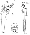
- Figure 1 is a schematic representation seen front view of a rod characteristic of the invention.
- Figure 2 is a side view of this rod, shown along the axis F2 perpendicular to the longitudinal axis P of the rod, while FIG. 3 is a view of top shown along the longitudinal axis F1 of the prosthetic neck.
- Figure 4 is a detailed representation of the assembly characteristic of the invention.
- Figure 5 is a schematic representation seen side of a rod characteristic of the invention according to another embodiment.
- Figure 6 is a representation of a detail of the proximal part of the rod conforming to that shown in Figure 5.
- Figure 7 is a schematic representation of the prosthetic neck conforming to the representation of the figure 5.
- Figure 8 is another representation of this pass prosthetic.
- Figure 9 is a schematic representation of the prosthetic neck at different inclinations.
- Figure 10 is a schematic representation representing different possible inclinations of the neck prosthetic with respect to the median plane of the stem.
- the rod according to the invention basically consists of two parts, namely a prosthetic neck designated by the general reference (1) and a rod proper designated by the general reference (10).
- the prosthetic neck (1) intended to protrude from the femur to be reinforced, comprises in order a head (2), slightly frustoconical, intended to receive by fitting a sphere not shown on which the acetabular cup rests.
- This frustoconical head (2) is connected in a known manner to a neck (3), then to a base (4), the base (5) of which is perpendicular to the axis F1 of the prosthetic neck (1).
- This base (5) has in its middle and directed towards the outside, a cylindrical fitting surface (6), orthogonal to the base (5).
- this bearing (6) can be slightly frustoconical (walrus cone from 3 to 5 °).
- the end (7) of this cylindrical seat (6) is slightly bevelled.
- this cylindrical bearing surface (6) has substantially at its middle an annular groove (8) in the shape of a V.
- the rod (10) comprises in known manner a proximal portion designated by the general reference (11), a distal portion designated by the general reference (12), and a tip (13).
- This rod (10) is intended to be inserted into the medullary canal of the femur to be reinforced.
- the rod (10) and more precisely the proximal portion (11) has, at the limit of the burial zone, designated by the general reference E , a base (15) parallel to the base (5) of the neck (1), therefore perpendicular to the axis F1 , so as to be complementary to this base (5).
- the base (5) of the rod has a cylindrical housing (16) (see Figure 4), into which is inserted side by side the scope of the fitting (6) and disposed next to it.
- the two complementary bases (5.15) each extend by a small inclined face respectively (9) and (17), parallel to the longitudinal axis of the rod (10), that is to say parallel to the plane P , so that these two bases (5,9; 15, 17) have a general asymmetrical V shape to form an anti-rotational stop.
- the upper part (20) of the proximal portion (11) has a threaded channel (21) parallel to the faces (9,17), therefore with the median plane P of the rod, intended to receive a screw (22), the end (23) teat shape to come engage in the groove (8), and more precisely to bear on one of the faces thereof, and thereby immobilize the prosthetic neck (1) in the rod (10).
- This channel (21) slightly protrudes from the burial zone (E) and is therefore easily accessible at surgeon.
- the angle ⁇ of the prosthetic neck (1) with respect to the median plane P of the stem is variable from one neck to the other, for example by five in five degrees and between plus and minus thirty degrees from this plane P.
- This angle ⁇ which varies by construction, thus allows the surgeon according to the positioning of the acetabulum, to choose the most suitable prosthetic neck (1).
- the angle ⁇ varies from five to five degrees in a range between plus and minus thirty degrees relative to the median plane P of the rod.
- the length of the prosthetic neck (1) is between thirty and fifty millimeters, and the angle ⁇ formed by the base (15) proximal with the longitudinal axis of the rod, is close to forty eight to fifty degrees .
- the prosthetic neck (1) comprises a base (5) completely flat and perpendicular to the angle F1 of the neck.
- This prosthetic neck comprises as means of attachment a morse cone (24) of slightly conical shape, intended to cooperate with a complementary recess (25) formed by the base (15) of the proximal part (11) of the rod, and in look of said morse cone when the neck is in place on the rod.
- the neck (1) also includes a through hole (30) located in the same plane as said walrus cone (24), and further located in the same plane as the median plane P of the rod (10).
- This obviously (30) is intended to allow insertion a locking screw (26), intended to cooperate with a corresponding obviously (32) arranged in the base of the proximal part (11) of the rod, and more precisely at the tapped lower end (28), intended to cooperate with the thread (27) of the end of the screw (26).
- the walrus cone (24) and the screw (26) are concurrent when the cone is in place on the rod, so on the one hand, reduce the size of the recesses corresponding to the level of the rod, and on the other hand, to reinforce the mechanical resistance of the rod in particular in flexion.
- the rod head (29) is retracted when the screw is in square. In this way, the prosthetic neck is prevented from forming cam during certain movements of the patient on which is set up the prosthesis.
- the prosthesis according to the invention is characterized by its simplicity, its ease of implementation, and by the does not weaken the bone to be strengthened.
- This multiplicity of adaptation is further accentuated by the fact that the length of the head (2) of the neck is variable.
- the mechanical resistance of the prostheses thus produced is finds greatly increased, especially for the efforts of shear and bending.
Description
- tout d'abord, un col prothétique, destiné à dépasser du fémur et dont l'extrémité présente une tête généralement conique, destinée à recevoir une sphère sur laquelle s'appuie la cupule cotyloïdienne ;
- ensuite, une tige proprement dite, destinée à être insérée dans le fémur à renforcer, comportant une portion proximale raccordée au col prothétique, et une portion distale dont la pointe est engagée dans le canal médullaire du fémur.
- une tige proprement dite, destinée à être insérée dans le fémur à
renforcer, comprenant :
- une portion proximale raccordée à un col prothétique, et présentant une embase de raccordement audit col ;
- et une portion distale ;
- un col prothétique choisi parmi une pluralité de cols prothétiques, dont l'angle α par rapport au plan médian P de la tige varie et est compris entre plus et moins trente degrés, le col étant destiné à dépasser du fémur, dont l'extrémité reçoit une sphère, et dont la base présente une embase complémentaire de l'embase proximale de la tige,
- un cone morse émergeant perpendiculairement de l'embase du col prothétique, destiné à coopérer avec un logement de forme et de dimension complémentaires réalisé en regard dans l'embase de la tige ;
- une vis de verrouillage, destinée à venir s'insérer dans un évidement ménagé à cet effet au niveau de l'embase dudit col, et à venir à coopérer avec un orifice taraudé de manière complémentaire ménagé dans l'embase de la tige.
Claims (7)
- Tige fémorale perfectionnée pour prothèse de hanche réalisée en deux parties distinctes, respectivement :ladite embase (15) de raccordement de la tige (10) audit col prothétique (1) étant située dans un plan non perpendiculaire à l'axe longitudinal de ladite tige (10), et les deux embases complémentaires (5, 15) présentant des moyens complémentaires (4, 6, 7, 8, 16, 17, 18, 24-31) de solidarisation du col (1) sur la tige (10).une tige proprement dite (10), destinée à être insérée dans le fémur à renforcer, comprenant :une portion proximale (11) raccordée à un col prothétique (1), et présentant une embase de raccordement (15) audit col (1) ;et une portion distale ;un col prothétique choisi parmi une pluralité de cols prothétiques (1), dont l'angle α par rapport au plan médian P de la tige (10) varie et est compris entre plus et moins trente degrés, le col étant destiné à dépasser du fémur, dont l'extrémité (2) reçoit une sphère, et dont la base (4) présente une embase (5) complémentaire de l'embase proximale (15) de la tige (10) ,
- Tige fémorale selon la revendication 1, caractérisée en ce que les moyens complémentaires de solidarisation sont constitués respectivement par une portée cylindrique (6) d'emmanchement mâle disposée sur l'embase (5) du col (1), et par un logement cylindrique complémentaire (16) ménagé en regard dans l'embase (5) de la tige (10), la portée mâle (6) présentant un logement annulaire (8), destiné à coopérer avec l'extrémité (23) d'une vis (22) d'immobilisation ménagée dans un logement fileté (21) taillé dans le haut (20) de la tige (10).
- Tige fémorale perfectionnée selon l'une des revendications 1 et 2, caractérisée en ce que les deux embases complémentaires (5,15) ont une forme générale en V asymétrique et comprennent une grande embase (5,15) proprement dite, associée à une petite face inclinée (9,17) parallèle à l'axe longitudinal de la tige, de manière à former butée antirotatoire.
- Tige fémorale selon l'une des revendications 1 à 3, caractérisée en ce que l'angle α du col prothétique (1) par rapport au plan médian P de la tige (10) varie de cinq en cinq degrés d'un col (1) à l'autre de la pluralité de cols prothétiques parmi lequel ledit col est choisi.
- Tige fémorale selon la revendication 1, caractérisée en ce que l'embase (5) du col prothétique (1) est totalement plane, et en ce que les moyens de solidarisation sont constitués :par un cone-morse (24), emergeant perpendiculairement de l'embase (5) du col (1), destiné à coopérer avec un logement (25), de forme et dimension complémentaires, réalisé dans la partie proximale (11) de la tige (10), et débouchant au niveau de l'embase (15) de celle-ci en regard dudit cone (24) ;par une vis de verrouillage (26), destinée à venir s'insérer dans un évidement (30) ménagé à cet effet au niveau de l'embase (5) du col (1), et destinée à coopérer avec un orifice taraudé (28) de manière complémentaire, ménagé dans la partie proximale (11) de la tige (10), et débouchant au niveau de l'embase (15).
- Tige fémorale selon la revendication 5, caractérisée en ce que la vis de verrouillage (26) et le cone-morse (24) sont situés dans le même plan, lui-même coplanaire avec le plan médian P de la tige (10).
- Tige fémorale selon l'une des revendications 5 et 6, caractérisée en ce que la vis de verrouillage (26) et le cone-morse (24) sont concourants, l'angle qu'ils définissent étant compris entre 10 et 20 degrés.
Applications Claiming Priority (2)
| Application Number | Priority Date | Filing Date | Title |
|---|---|---|---|
| FR9014106A FR2668702B1 (fr) | 1990-11-06 | 1990-11-06 | Tige femorale perfectionnee pour prothese de hanche. |
| FR9014106 | 1990-11-06 |
Publications (2)
| Publication Number | Publication Date |
|---|---|
| EP0485311A1 EP0485311A1 (fr) | 1992-05-13 |
| EP0485311B1 true EP0485311B1 (fr) | 1998-08-12 |
Family
ID=9402150
Family Applications (1)
| Application Number | Title | Priority Date | Filing Date |
|---|---|---|---|
| EP19910420391 Expired - Lifetime EP0485311B1 (fr) | 1990-11-06 | 1991-11-05 | Tige fémorale perfectionnée pour prothèse de hanche |
Country Status (4)
| Country | Link |
|---|---|
| EP (1) | EP0485311B1 (fr) |
| DE (1) | DE69129969T2 (fr) |
| ES (1) | ES2119766T3 (fr) |
| FR (1) | FR2668702B1 (fr) |
Cited By (1)
| Publication number | Priority date | Publication date | Assignee | Title |
|---|---|---|---|---|
| DE102005006316A1 (de) * | 2005-02-11 | 2006-08-24 | Nowakowski, Andrej, Dr. med. Dipl.-Ing.(FH) | Hüftgelenk-Endoprothesensystem |
Families Citing this family (18)
| Publication number | Priority date | Publication date | Assignee | Title |
|---|---|---|---|---|
| FR2701836B1 (fr) * | 1993-02-22 | 1998-01-30 | Medinov Sa | Col modulaire pour tige fémorale de prothèse de hanche. |
| FR2723308B1 (fr) | 1994-08-02 | 1996-12-13 | Impact | Prothese de hanche perfectionnee |
| FR2753081B1 (fr) * | 1996-09-11 | 1999-03-05 | Daniel Noyer | Prothese femorale de hanche a embase antepulsee |
| GB9620998D0 (en) * | 1996-10-09 | 1996-11-27 | Minnesota Mining & Mfg | Shoulder prosthesis |
| FR2760966B1 (fr) * | 1997-03-21 | 1999-07-23 | Merck Biomaterial France | Prothese de hanche |
| GB9707371D0 (en) | 1997-04-11 | 1997-05-28 | Minnesota Mining & Mfg | A modular humeral prosthesis |
| US6120544A (en) * | 1997-05-16 | 2000-09-19 | Eska Implants Gmbh & Co. | Femur endoprosthesis for articial hip joint |
| US7189261B2 (en) | 1998-04-03 | 2007-03-13 | Smith & Nephew, Inc. | Modular humeral prosthesis and method |
| GB9828084D0 (en) * | 1998-12-18 | 1999-02-17 | Benoist Girard & Cie | Femoral component |
| IT1316060B1 (it) * | 1999-07-27 | 2003-03-28 | Tecnomeccanica Srl | Protesi di anca bilaterale antilussante. |
| DE20007950U1 (de) * | 2000-05-03 | 2000-07-20 | Aesculap Ag & Co Kg | Schenkelhalsprothese |
| US7097663B1 (en) | 2001-12-17 | 2006-08-29 | Smith & Nephew, Inc. | Modular prosthesis system with novel locking mechanism |
| DE10252123B3 (de) * | 2002-11-05 | 2004-07-22 | Eska Implants Gmbh & Co. | Set zur Erstellung eines künstlichen Hüftgelenkes |
| DE102004038281B3 (de) * | 2004-08-03 | 2006-05-11 | Endoplant Gmbh | Schenkelhalsprothese |
| EP2001413A2 (fr) * | 2006-03-20 | 2008-12-17 | Zimmer Technology, Inc. | Implants de hanche prothétiques |
| FR2922436B1 (fr) * | 2007-10-17 | 2010-01-08 | Levon Doursounian | Element femoral de prothese de hanche, et prothese totale de hanche le comportant. |
| US9101477B2 (en) | 2011-10-17 | 2015-08-11 | Thomas Hatton McCoy | Anterior offset component for total hip replacement |
| FR2985172B1 (fr) * | 2012-01-04 | 2014-02-14 | Wilko Fockens | Prothese d'epaule sur fracture avec mecanisme d'assemblage retentif et universel |
Family Cites Families (7)
| Publication number | Priority date | Publication date | Assignee | Title |
|---|---|---|---|---|
| SU440014A1 (ru) * | 1972-05-04 | 1978-08-05 | Саратовский государственный медицинский институт | Эндропротез проксимального конца бедренной кости |
| FR2366005A2 (fr) * | 1976-07-28 | 1978-04-28 | Mahay Cie | Prothese totale de la hanche |
| DE2734249A1 (de) * | 1977-07-29 | 1979-02-08 | Bayer Ag | Oberschenkelhalsprothese |
| US4608055A (en) * | 1984-01-12 | 1986-08-26 | Mayo Foundation | Femoral component for hip prosthesis |
| FR2596642B1 (fr) * | 1986-04-04 | 1988-06-24 | Demeulenaere Claude | Prothese de hanche |
| FR2640497B1 (fr) * | 1988-12-19 | 1997-10-03 | Mesguich Alain | Implant femoral pour prothese de hanche |
| US4963155A (en) * | 1989-08-30 | 1990-10-16 | Zimmer, Inc. | Attachment mechanism for modular surgical products |
-
1990
- 1990-11-06 FR FR9014106A patent/FR2668702B1/fr not_active Expired - Fee Related
-
1991
- 1991-11-05 EP EP19910420391 patent/EP0485311B1/fr not_active Expired - Lifetime
- 1991-11-05 DE DE1991629969 patent/DE69129969T2/de not_active Expired - Fee Related
- 1991-11-05 ES ES91420391T patent/ES2119766T3/es not_active Expired - Lifetime
Cited By (1)
| Publication number | Priority date | Publication date | Assignee | Title |
|---|---|---|---|---|
| DE102005006316A1 (de) * | 2005-02-11 | 2006-08-24 | Nowakowski, Andrej, Dr. med. Dipl.-Ing.(FH) | Hüftgelenk-Endoprothesensystem |
Also Published As
| Publication number | Publication date |
|---|---|
| EP0485311A1 (fr) | 1992-05-13 |
| FR2668702B1 (fr) | 1995-06-09 |
| ES2119766T3 (es) | 1998-10-16 |
| DE69129969T2 (de) | 1998-12-24 |
| DE69129969D1 (de) | 1998-09-17 |
| FR2668702A1 (fr) | 1992-05-07 |
Similar Documents
| Publication | Publication Date | Title |
|---|---|---|
| EP0485311B1 (fr) | Tige fémorale perfectionnée pour prothèse de hanche | |
| EP0190981B1 (fr) | Prothèse totale de hanche à fixation primaire | |
| EP0259420B1 (fr) | Cupule de prothese | |
| EP0879031B1 (fr) | Prothese de hanche non luxable et peu usable | |
| EP0038897B1 (fr) | Prothèse intramédullaire non scellée pour articulation de la hanche | |
| FR2575383A1 (fr) | Prothese pour articulation diarthrose | |
| EP0797964A1 (fr) | Ensemble d'éléments pour la constitution d'une prothése totale de la hanche | |
| FR2860425A1 (fr) | Implant humeral pour prothese de l'epaule | |
| WO1991018560A1 (fr) | Prothese de hanche | |
| EP0711534B1 (fr) | Tige fémorale pour prothèse de hanche | |
| FR2647669A1 (fr) | Prothese de hanche anatomique | |
| FR2606273A1 (fr) | Prothese d'articulation perfectionnee | |
| FR2683717A1 (fr) | Tige femorale pour prothese totale de hanche. | |
| FR2903882A1 (fr) | Insert pour implant cotyloidien a double mobilite, implant cotyloidien correspondant et prothese de hanche correspondante | |
| EP0241361A1 (fr) | Prothèse de hanche | |
| FR2575384A1 (fr) | Prothese femorale et ancillaire correspondant | |
| EP0354142B1 (fr) | Tige pour prothèse totale de hanche | |
| FR2626169A1 (fr) | Prothese de hanche | |
| FR2751528A1 (fr) | Prothese de hanche | |
| FR2799115A1 (fr) | Tige modulaire pour prothese de hanche | |
| FR2681239A1 (fr) | Tige pour prothese totale de hanche. | |
| FR2721201A1 (fr) | Prothèse cotyloïdienne, son utilisation en vue de réduire l'usure, le fluage et le basculement et favoriser la repousse osseuse et instrumentation ancillaire pour sa mise en place. | |
| FR2788429A1 (fr) | Ensemble de pieces pour la constitution d'une tige femorale de prothese de hanche | |
| FR2760966A1 (fr) | Prothese de hanche | |
| FR2827155A1 (fr) | Tige femorale pour prothese de hanche |
Legal Events
| Date | Code | Title | Description |
|---|---|---|---|
| PUAI | Public reference made under article 153(3) epc to a published international application that has entered the european phase |
Free format text: ORIGINAL CODE: 0009012 |
|
| AK | Designated contracting states |
Kind code of ref document: A1 Designated state(s): BE CH DE ES FR GB IT LI |
|
| 17P | Request for examination filed |
Effective date: 19920727 |
|
| 17Q | First examination report despatched |
Effective date: 19931112 |
|
| GRAG | Despatch of communication of intention to grant |
Free format text: ORIGINAL CODE: EPIDOS AGRA |
|
| RAP1 | Party data changed (applicant data changed or rights of an application transferred) |
Owner name: MERCK BIOMATERIAL FRANCE |
|
| APAB | Appeal dossier modified |
Free format text: ORIGINAL CODE: EPIDOS NOAPE |
|
| APAB | Appeal dossier modified |
Free format text: ORIGINAL CODE: EPIDOS NOAPE |
|
| APAD | Appeal reference recorded |
Free format text: ORIGINAL CODE: EPIDOS REFNE |
|
| APAB | Appeal dossier modified |
Free format text: ORIGINAL CODE: EPIDOS NOAPE |
|
| APAB | Appeal dossier modified |
Free format text: ORIGINAL CODE: EPIDOS NOAPE |
|
| GRAG | Despatch of communication of intention to grant |
Free format text: ORIGINAL CODE: EPIDOS AGRA |
|
| GRAG | Despatch of communication of intention to grant |
Free format text: ORIGINAL CODE: EPIDOS AGRA |
|
| GRAH | Despatch of communication of intention to grant a patent |
Free format text: ORIGINAL CODE: EPIDOS IGRA |
|
| GRAH | Despatch of communication of intention to grant a patent |
Free format text: ORIGINAL CODE: EPIDOS IGRA |
|
| RAP1 | Party data changed (applicant data changed or rights of an application transferred) |
Owner name: MERCK BIOMATERIAL FRANCE |
|
| GRAA | (expected) grant |
Free format text: ORIGINAL CODE: 0009210 |
|
| AK | Designated contracting states |
Kind code of ref document: B1 Designated state(s): BE CH DE ES FR GB IT LI |
|
| PG25 | Lapsed in a contracting state [announced via postgrant information from national office to epo] |
Ref country code: IT Free format text: LAPSE BECAUSE OF FAILURE TO SUBMIT A TRANSLATION OF THE DESCRIPTION OR TO PAY THE FEE WITHIN THE PRESCRIBED TIME-LIMIT;WARNING: LAPSES OF ITALIAN PATENTS WITH EFFECTIVE DATE BEFORE 2007 MAY HAVE OCCURRED AT ANY TIME BEFORE 2007. THE CORRECT EFFECTIVE DATE MAY BE DIFFERENT FROM THE ONE RECORDED. Effective date: 19980812 |
|
| REG | Reference to a national code |
Ref country code: CH Ref legal event code: EP |
|
| REF | Corresponds to: |
Ref document number: 69129969 Country of ref document: DE Date of ref document: 19980917 |
|
| REG | Reference to a national code |
Ref country code: ES Ref legal event code: FG2A Ref document number: 2119766 Country of ref document: ES Kind code of ref document: T3 |
|
| GBT | Gb: translation of ep patent filed (gb section 77(6)(a)/1977) |
Effective date: 19981014 |
|
| PGFP | Annual fee paid to national office [announced via postgrant information from national office to epo] |
Ref country code: ES Payment date: 19981116 Year of fee payment: 8 |
|
| PGFP | Annual fee paid to national office [announced via postgrant information from national office to epo] |
Ref country code: CH Payment date: 19981119 Year of fee payment: 8 |
|
| PGFP | Annual fee paid to national office [announced via postgrant information from national office to epo] |
Ref country code: BE Payment date: 19981210 Year of fee payment: 8 |
|
| PLBE | No opposition filed within time limit |
Free format text: ORIGINAL CODE: 0009261 |
|
| STAA | Information on the status of an ep patent application or granted ep patent |
Free format text: STATUS: NO OPPOSITION FILED WITHIN TIME LIMIT |
|
| 26N | No opposition filed | ||
| PGFP | Annual fee paid to national office [announced via postgrant information from national office to epo] |
Ref country code: GB Payment date: 19991029 Year of fee payment: 9 |
|
| PG25 | Lapsed in a contracting state [announced via postgrant information from national office to epo] |
Ref country code: ES Free format text: LAPSE BECAUSE OF NON-PAYMENT OF DUE FEES Effective date: 19991106 |
|
| PGFP | Annual fee paid to national office [announced via postgrant information from national office to epo] |
Ref country code: DE Payment date: 19991115 Year of fee payment: 9 |
|
| PG25 | Lapsed in a contracting state [announced via postgrant information from national office to epo] |
Ref country code: LI Free format text: LAPSE BECAUSE OF NON-PAYMENT OF DUE FEES Effective date: 19991130 Ref country code: CH Free format text: LAPSE BECAUSE OF NON-PAYMENT OF DUE FEES Effective date: 19991130 Ref country code: BE Free format text: LAPSE BECAUSE OF NON-PAYMENT OF DUE FEES Effective date: 19991130 |
|
| BERE | Be: lapsed |
Owner name: MERCK BIOMATERIAL FRANCE Effective date: 19991130 |
|
| REG | Reference to a national code |
Ref country code: CH Ref legal event code: PL |
|
| PG25 | Lapsed in a contracting state [announced via postgrant information from national office to epo] |
Ref country code: GB Free format text: LAPSE BECAUSE OF NON-PAYMENT OF DUE FEES Effective date: 20001105 |
|
| GBPC | Gb: european patent ceased through non-payment of renewal fee |
Effective date: 20001105 |
|
| PG25 | Lapsed in a contracting state [announced via postgrant information from national office to epo] |
Ref country code: DE Free format text: LAPSE BECAUSE OF NON-PAYMENT OF DUE FEES Effective date: 20010801 |
|
| PGFP | Annual fee paid to national office [announced via postgrant information from national office to epo] |
Ref country code: FR Payment date: 20031127 Year of fee payment: 13 |
|
| REG | Reference to a national code |
Ref country code: ES Ref legal event code: FD2A Effective date: 20001214 |
|
| PG25 | Lapsed in a contracting state [announced via postgrant information from national office to epo] |
Ref country code: FR Free format text: LAPSE BECAUSE OF NON-PAYMENT OF DUE FEES Effective date: 20050729 |
|
| REG | Reference to a national code |
Ref country code: FR Ref legal event code: ST |
|
| APAH | Appeal reference modified |
Free format text: ORIGINAL CODE: EPIDOSCREFNO |