EP0485311B1 - Stem for hip prosthesis - Google Patents
Stem for hip prosthesis Download PDFInfo
- Publication number
- EP0485311B1 EP0485311B1 EP19910420391 EP91420391A EP0485311B1 EP 0485311 B1 EP0485311 B1 EP 0485311B1 EP 19910420391 EP19910420391 EP 19910420391 EP 91420391 A EP91420391 A EP 91420391A EP 0485311 B1 EP0485311 B1 EP 0485311B1
- Authority
- EP
- European Patent Office
- Prior art keywords
- stem
- neck
- shoulder
- prosthetic
- complementary
- Prior art date
- Legal status (The legal status is an assumption and is not a legal conclusion. Google has not performed a legal analysis and makes no representation as to the accuracy of the status listed.)
- Expired - Lifetime
Links
Images


Classifications
-
- A—HUMAN NECESSITIES
- A61—MEDICAL OR VETERINARY SCIENCE; HYGIENE
- A61F—FILTERS IMPLANTABLE INTO BLOOD VESSELS; PROSTHESES; DEVICES PROVIDING PATENCY TO, OR PREVENTING COLLAPSING OF, TUBULAR STRUCTURES OF THE BODY, e.g. STENTS; ORTHOPAEDIC, NURSING OR CONTRACEPTIVE DEVICES; FOMENTATION; TREATMENT OR PROTECTION OF EYES OR EARS; BANDAGES, DRESSINGS OR ABSORBENT PADS; FIRST-AID KITS
- A61F2/00—Filters implantable into blood vessels; Prostheses, i.e. artificial substitutes or replacements for parts of the body; Appliances for connecting them with the body; Devices providing patency to, or preventing collapsing of, tubular structures of the body, e.g. stents
- A61F2/02—Prostheses implantable into the body
- A61F2/30—Joints
- A61F2/32—Joints for the hip
- A61F2/36—Femoral heads ; Femoral endoprostheses
- A61F2/3609—Femoral heads or necks; Connections of endoprosthetic heads or necks to endoprosthetic femoral shafts
-
- A—HUMAN NECESSITIES
- A61—MEDICAL OR VETERINARY SCIENCE; HYGIENE
- A61F—FILTERS IMPLANTABLE INTO BLOOD VESSELS; PROSTHESES; DEVICES PROVIDING PATENCY TO, OR PREVENTING COLLAPSING OF, TUBULAR STRUCTURES OF THE BODY, e.g. STENTS; ORTHOPAEDIC, NURSING OR CONTRACEPTIVE DEVICES; FOMENTATION; TREATMENT OR PROTECTION OF EYES OR EARS; BANDAGES, DRESSINGS OR ABSORBENT PADS; FIRST-AID KITS
- A61F2/00—Filters implantable into blood vessels; Prostheses, i.e. artificial substitutes or replacements for parts of the body; Appliances for connecting them with the body; Devices providing patency to, or preventing collapsing of, tubular structures of the body, e.g. stents
- A61F2/02—Prostheses implantable into the body
- A61F2/30—Joints
- A61F2/32—Joints for the hip
- A61F2/36—Femoral heads ; Femoral endoprostheses
- A61F2/3662—Femoral shafts
- A61F2/367—Proximal or metaphyseal parts of shafts
-
- A—HUMAN NECESSITIES
- A61—MEDICAL OR VETERINARY SCIENCE; HYGIENE
- A61F—FILTERS IMPLANTABLE INTO BLOOD VESSELS; PROSTHESES; DEVICES PROVIDING PATENCY TO, OR PREVENTING COLLAPSING OF, TUBULAR STRUCTURES OF THE BODY, e.g. STENTS; ORTHOPAEDIC, NURSING OR CONTRACEPTIVE DEVICES; FOMENTATION; TREATMENT OR PROTECTION OF EYES OR EARS; BANDAGES, DRESSINGS OR ABSORBENT PADS; FIRST-AID KITS
- A61F2/00—Filters implantable into blood vessels; Prostheses, i.e. artificial substitutes or replacements for parts of the body; Appliances for connecting them with the body; Devices providing patency to, or preventing collapsing of, tubular structures of the body, e.g. stents
- A61F2/02—Prostheses implantable into the body
- A61F2/30—Joints
- A61F2/32—Joints for the hip
- A61F2/36—Femoral heads ; Femoral endoprostheses
- A61F2/3662—Femoral shafts
- A61F2/3676—Distal or diaphyseal parts of shafts
-
- A—HUMAN NECESSITIES
- A61—MEDICAL OR VETERINARY SCIENCE; HYGIENE
- A61F—FILTERS IMPLANTABLE INTO BLOOD VESSELS; PROSTHESES; DEVICES PROVIDING PATENCY TO, OR PREVENTING COLLAPSING OF, TUBULAR STRUCTURES OF THE BODY, e.g. STENTS; ORTHOPAEDIC, NURSING OR CONTRACEPTIVE DEVICES; FOMENTATION; TREATMENT OR PROTECTION OF EYES OR EARS; BANDAGES, DRESSINGS OR ABSORBENT PADS; FIRST-AID KITS
- A61F2/00—Filters implantable into blood vessels; Prostheses, i.e. artificial substitutes or replacements for parts of the body; Appliances for connecting them with the body; Devices providing patency to, or preventing collapsing of, tubular structures of the body, e.g. stents
- A61F2/02—Prostheses implantable into the body
- A61F2/30—Joints
- A61F2002/30001—Additional features of subject-matter classified in A61F2/28, A61F2/30 and subgroups thereof
- A61F2002/30108—Shapes
- A61F2002/30199—Three-dimensional shapes
- A61F2002/30205—Three-dimensional shapes conical
- A61F2002/3021—Three-dimensional shapes conical frustoconical
-
- A—HUMAN NECESSITIES
- A61—MEDICAL OR VETERINARY SCIENCE; HYGIENE
- A61F—FILTERS IMPLANTABLE INTO BLOOD VESSELS; PROSTHESES; DEVICES PROVIDING PATENCY TO, OR PREVENTING COLLAPSING OF, TUBULAR STRUCTURES OF THE BODY, e.g. STENTS; ORTHOPAEDIC, NURSING OR CONTRACEPTIVE DEVICES; FOMENTATION; TREATMENT OR PROTECTION OF EYES OR EARS; BANDAGES, DRESSINGS OR ABSORBENT PADS; FIRST-AID KITS
- A61F2/00—Filters implantable into blood vessels; Prostheses, i.e. artificial substitutes or replacements for parts of the body; Appliances for connecting them with the body; Devices providing patency to, or preventing collapsing of, tubular structures of the body, e.g. stents
- A61F2/02—Prostheses implantable into the body
- A61F2/30—Joints
- A61F2002/30001—Additional features of subject-matter classified in A61F2/28, A61F2/30 and subgroups thereof
- A61F2002/30316—The prosthesis having different structural features at different locations within the same prosthesis; Connections between prosthetic parts; Special structural features of bone or joint prostheses not otherwise provided for
- A61F2002/30329—Connections or couplings between prosthetic parts, e.g. between modular parts; Connecting elements
- A61F2002/30331—Connections or couplings between prosthetic parts, e.g. between modular parts; Connecting elements made by longitudinally pushing a protrusion into a complementarily-shaped recess, e.g. held by friction fit
- A61F2002/30332—Conically- or frustoconically-shaped protrusion and recess
-
- A—HUMAN NECESSITIES
- A61—MEDICAL OR VETERINARY SCIENCE; HYGIENE
- A61F—FILTERS IMPLANTABLE INTO BLOOD VESSELS; PROSTHESES; DEVICES PROVIDING PATENCY TO, OR PREVENTING COLLAPSING OF, TUBULAR STRUCTURES OF THE BODY, e.g. STENTS; ORTHOPAEDIC, NURSING OR CONTRACEPTIVE DEVICES; FOMENTATION; TREATMENT OR PROTECTION OF EYES OR EARS; BANDAGES, DRESSINGS OR ABSORBENT PADS; FIRST-AID KITS
- A61F2/00—Filters implantable into blood vessels; Prostheses, i.e. artificial substitutes or replacements for parts of the body; Appliances for connecting them with the body; Devices providing patency to, or preventing collapsing of, tubular structures of the body, e.g. stents
- A61F2/02—Prostheses implantable into the body
- A61F2/30—Joints
- A61F2002/30001—Additional features of subject-matter classified in A61F2/28, A61F2/30 and subgroups thereof
- A61F2002/30316—The prosthesis having different structural features at different locations within the same prosthesis; Connections between prosthetic parts; Special structural features of bone or joint prostheses not otherwise provided for
- A61F2002/30329—Connections or couplings between prosthetic parts, e.g. between modular parts; Connecting elements
- A61F2002/30331—Connections or couplings between prosthetic parts, e.g. between modular parts; Connecting elements made by longitudinally pushing a protrusion into a complementarily-shaped recess, e.g. held by friction fit
- A61F2002/30354—Cylindrically-shaped protrusion and recess, e.g. cylinder of circular basis
-
- A—HUMAN NECESSITIES
- A61—MEDICAL OR VETERINARY SCIENCE; HYGIENE
- A61F—FILTERS IMPLANTABLE INTO BLOOD VESSELS; PROSTHESES; DEVICES PROVIDING PATENCY TO, OR PREVENTING COLLAPSING OF, TUBULAR STRUCTURES OF THE BODY, e.g. STENTS; ORTHOPAEDIC, NURSING OR CONTRACEPTIVE DEVICES; FOMENTATION; TREATMENT OR PROTECTION OF EYES OR EARS; BANDAGES, DRESSINGS OR ABSORBENT PADS; FIRST-AID KITS
- A61F2/00—Filters implantable into blood vessels; Prostheses, i.e. artificial substitutes or replacements for parts of the body; Appliances for connecting them with the body; Devices providing patency to, or preventing collapsing of, tubular structures of the body, e.g. stents
- A61F2/02—Prostheses implantable into the body
- A61F2/30—Joints
- A61F2002/30001—Additional features of subject-matter classified in A61F2/28, A61F2/30 and subgroups thereof
- A61F2002/30316—The prosthesis having different structural features at different locations within the same prosthesis; Connections between prosthetic parts; Special structural features of bone or joint prostheses not otherwise provided for
- A61F2002/30329—Connections or couplings between prosthetic parts, e.g. between modular parts; Connecting elements
- A61F2002/30476—Connections or couplings between prosthetic parts, e.g. between modular parts; Connecting elements locked by an additional locking mechanism
- A61F2002/30507—Connections or couplings between prosthetic parts, e.g. between modular parts; Connecting elements locked by an additional locking mechanism using a threaded locking member, e.g. a locking screw or a set screw
-
- A—HUMAN NECESSITIES
- A61—MEDICAL OR VETERINARY SCIENCE; HYGIENE
- A61F—FILTERS IMPLANTABLE INTO BLOOD VESSELS; PROSTHESES; DEVICES PROVIDING PATENCY TO, OR PREVENTING COLLAPSING OF, TUBULAR STRUCTURES OF THE BODY, e.g. STENTS; ORTHOPAEDIC, NURSING OR CONTRACEPTIVE DEVICES; FOMENTATION; TREATMENT OR PROTECTION OF EYES OR EARS; BANDAGES, DRESSINGS OR ABSORBENT PADS; FIRST-AID KITS
- A61F2/00—Filters implantable into blood vessels; Prostheses, i.e. artificial substitutes or replacements for parts of the body; Appliances for connecting them with the body; Devices providing patency to, or preventing collapsing of, tubular structures of the body, e.g. stents
- A61F2/02—Prostheses implantable into the body
- A61F2/30—Joints
- A61F2002/30001—Additional features of subject-matter classified in A61F2/28, A61F2/30 and subgroups thereof
- A61F2002/30316—The prosthesis having different structural features at different locations within the same prosthesis; Connections between prosthetic parts; Special structural features of bone or joint prostheses not otherwise provided for
- A61F2002/30535—Special structural features of bone or joint prostheses not otherwise provided for
- A61F2002/30604—Special structural features of bone or joint prostheses not otherwise provided for modular
- A61F2002/30616—Sets comprising a plurality of prosthetic parts of different sizes or orientations
-
- A—HUMAN NECESSITIES
- A61—MEDICAL OR VETERINARY SCIENCE; HYGIENE
- A61F—FILTERS IMPLANTABLE INTO BLOOD VESSELS; PROSTHESES; DEVICES PROVIDING PATENCY TO, OR PREVENTING COLLAPSING OF, TUBULAR STRUCTURES OF THE BODY, e.g. STENTS; ORTHOPAEDIC, NURSING OR CONTRACEPTIVE DEVICES; FOMENTATION; TREATMENT OR PROTECTION OF EYES OR EARS; BANDAGES, DRESSINGS OR ABSORBENT PADS; FIRST-AID KITS
- A61F2/00—Filters implantable into blood vessels; Prostheses, i.e. artificial substitutes or replacements for parts of the body; Appliances for connecting them with the body; Devices providing patency to, or preventing collapsing of, tubular structures of the body, e.g. stents
- A61F2/02—Prostheses implantable into the body
- A61F2/30—Joints
- A61F2/30767—Special external or bone-contacting surface, e.g. coating for improving bone ingrowth
- A61F2/30771—Special external or bone-contacting surface, e.g. coating for improving bone ingrowth applied in original prostheses, e.g. holes or grooves
- A61F2002/30772—Apertures or holes, e.g. of circular cross section
- A61F2002/30774—Apertures or holes, e.g. of circular cross section internally-threaded
-
- A—HUMAN NECESSITIES
- A61—MEDICAL OR VETERINARY SCIENCE; HYGIENE
- A61F—FILTERS IMPLANTABLE INTO BLOOD VESSELS; PROSTHESES; DEVICES PROVIDING PATENCY TO, OR PREVENTING COLLAPSING OF, TUBULAR STRUCTURES OF THE BODY, e.g. STENTS; ORTHOPAEDIC, NURSING OR CONTRACEPTIVE DEVICES; FOMENTATION; TREATMENT OR PROTECTION OF EYES OR EARS; BANDAGES, DRESSINGS OR ABSORBENT PADS; FIRST-AID KITS
- A61F2/00—Filters implantable into blood vessels; Prostheses, i.e. artificial substitutes or replacements for parts of the body; Appliances for connecting them with the body; Devices providing patency to, or preventing collapsing of, tubular structures of the body, e.g. stents
- A61F2/02—Prostheses implantable into the body
- A61F2/30—Joints
- A61F2/30767—Special external or bone-contacting surface, e.g. coating for improving bone ingrowth
- A61F2/30771—Special external or bone-contacting surface, e.g. coating for improving bone ingrowth applied in original prostheses, e.g. holes or grooves
- A61F2002/30795—Blind bores, e.g. of circular cross-section
- A61F2002/30797—Blind bores, e.g. of circular cross-section internally-threaded
-
- A—HUMAN NECESSITIES
- A61—MEDICAL OR VETERINARY SCIENCE; HYGIENE
- A61F—FILTERS IMPLANTABLE INTO BLOOD VESSELS; PROSTHESES; DEVICES PROVIDING PATENCY TO, OR PREVENTING COLLAPSING OF, TUBULAR STRUCTURES OF THE BODY, e.g. STENTS; ORTHOPAEDIC, NURSING OR CONTRACEPTIVE DEVICES; FOMENTATION; TREATMENT OR PROTECTION OF EYES OR EARS; BANDAGES, DRESSINGS OR ABSORBENT PADS; FIRST-AID KITS
- A61F2/00—Filters implantable into blood vessels; Prostheses, i.e. artificial substitutes or replacements for parts of the body; Appliances for connecting them with the body; Devices providing patency to, or preventing collapsing of, tubular structures of the body, e.g. stents
- A61F2/02—Prostheses implantable into the body
- A61F2/30—Joints
- A61F2/30767—Special external or bone-contacting surface, e.g. coating for improving bone ingrowth
- A61F2/30771—Special external or bone-contacting surface, e.g. coating for improving bone ingrowth applied in original prostheses, e.g. holes or grooves
- A61F2002/3082—Grooves
- A61F2002/30822—Circumferential grooves
-
- A—HUMAN NECESSITIES
- A61—MEDICAL OR VETERINARY SCIENCE; HYGIENE
- A61F—FILTERS IMPLANTABLE INTO BLOOD VESSELS; PROSTHESES; DEVICES PROVIDING PATENCY TO, OR PREVENTING COLLAPSING OF, TUBULAR STRUCTURES OF THE BODY, e.g. STENTS; ORTHOPAEDIC, NURSING OR CONTRACEPTIVE DEVICES; FOMENTATION; TREATMENT OR PROTECTION OF EYES OR EARS; BANDAGES, DRESSINGS OR ABSORBENT PADS; FIRST-AID KITS
- A61F2/00—Filters implantable into blood vessels; Prostheses, i.e. artificial substitutes or replacements for parts of the body; Appliances for connecting them with the body; Devices providing patency to, or preventing collapsing of, tubular structures of the body, e.g. stents
- A61F2/02—Prostheses implantable into the body
- A61F2/30—Joints
- A61F2/32—Joints for the hip
- A61F2/36—Femoral heads ; Femoral endoprostheses
- A61F2/3609—Femoral heads or necks; Connections of endoprosthetic heads or necks to endoprosthetic femoral shafts
- A61F2002/3625—Necks
- A61F2002/3647—Necks pierced with a longitudinal bore
-
- A—HUMAN NECESSITIES
- A61—MEDICAL OR VETERINARY SCIENCE; HYGIENE
- A61F—FILTERS IMPLANTABLE INTO BLOOD VESSELS; PROSTHESES; DEVICES PROVIDING PATENCY TO, OR PREVENTING COLLAPSING OF, TUBULAR STRUCTURES OF THE BODY, e.g. STENTS; ORTHOPAEDIC, NURSING OR CONTRACEPTIVE DEVICES; FOMENTATION; TREATMENT OR PROTECTION OF EYES OR EARS; BANDAGES, DRESSINGS OR ABSORBENT PADS; FIRST-AID KITS
- A61F2/00—Filters implantable into blood vessels; Prostheses, i.e. artificial substitutes or replacements for parts of the body; Appliances for connecting them with the body; Devices providing patency to, or preventing collapsing of, tubular structures of the body, e.g. stents
- A61F2/02—Prostheses implantable into the body
- A61F2/30—Joints
- A61F2/32—Joints for the hip
- A61F2/36—Femoral heads ; Femoral endoprostheses
- A61F2/3609—Femoral heads or necks; Connections of endoprosthetic heads or necks to endoprosthetic femoral shafts
- A61F2002/365—Connections of heads to necks
-
- A—HUMAN NECESSITIES
- A61—MEDICAL OR VETERINARY SCIENCE; HYGIENE
- A61F—FILTERS IMPLANTABLE INTO BLOOD VESSELS; PROSTHESES; DEVICES PROVIDING PATENCY TO, OR PREVENTING COLLAPSING OF, TUBULAR STRUCTURES OF THE BODY, e.g. STENTS; ORTHOPAEDIC, NURSING OR CONTRACEPTIVE DEVICES; FOMENTATION; TREATMENT OR PROTECTION OF EYES OR EARS; BANDAGES, DRESSINGS OR ABSORBENT PADS; FIRST-AID KITS
- A61F2/00—Filters implantable into blood vessels; Prostheses, i.e. artificial substitutes or replacements for parts of the body; Appliances for connecting them with the body; Devices providing patency to, or preventing collapsing of, tubular structures of the body, e.g. stents
- A61F2/02—Prostheses implantable into the body
- A61F2/30—Joints
- A61F2/32—Joints for the hip
- A61F2/36—Femoral heads ; Femoral endoprostheses
- A61F2/3609—Femoral heads or necks; Connections of endoprosthetic heads or necks to endoprosthetic femoral shafts
- A61F2002/3652—Connections of necks to shafts
-
- A—HUMAN NECESSITIES
- A61—MEDICAL OR VETERINARY SCIENCE; HYGIENE
- A61F—FILTERS IMPLANTABLE INTO BLOOD VESSELS; PROSTHESES; DEVICES PROVIDING PATENCY TO, OR PREVENTING COLLAPSING OF, TUBULAR STRUCTURES OF THE BODY, e.g. STENTS; ORTHOPAEDIC, NURSING OR CONTRACEPTIVE DEVICES; FOMENTATION; TREATMENT OR PROTECTION OF EYES OR EARS; BANDAGES, DRESSINGS OR ABSORBENT PADS; FIRST-AID KITS
- A61F2/00—Filters implantable into blood vessels; Prostheses, i.e. artificial substitutes or replacements for parts of the body; Appliances for connecting them with the body; Devices providing patency to, or preventing collapsing of, tubular structures of the body, e.g. stents
- A61F2/02—Prostheses implantable into the body
- A61F2/30—Joints
- A61F2/32—Joints for the hip
- A61F2/36—Femoral heads ; Femoral endoprostheses
- A61F2/3662—Femoral shafts
- A61F2002/3678—Geometrical features
- A61F2002/3694—Geometrical features with longitudinal bores
-
- A—HUMAN NECESSITIES
- A61—MEDICAL OR VETERINARY SCIENCE; HYGIENE
- A61F—FILTERS IMPLANTABLE INTO BLOOD VESSELS; PROSTHESES; DEVICES PROVIDING PATENCY TO, OR PREVENTING COLLAPSING OF, TUBULAR STRUCTURES OF THE BODY, e.g. STENTS; ORTHOPAEDIC, NURSING OR CONTRACEPTIVE DEVICES; FOMENTATION; TREATMENT OR PROTECTION OF EYES OR EARS; BANDAGES, DRESSINGS OR ABSORBENT PADS; FIRST-AID KITS
- A61F2220/00—Fixations or connections for prostheses classified in groups A61F2/00 - A61F2/26 or A61F2/82 or A61F9/00 or A61F11/00 or subgroups thereof
- A61F2220/0025—Connections or couplings between prosthetic parts, e.g. between modular parts; Connecting elements
- A61F2220/0033—Connections or couplings between prosthetic parts, e.g. between modular parts; Connecting elements made by longitudinally pushing a protrusion into a complementary-shaped recess, e.g. held by friction fit
-
- A—HUMAN NECESSITIES
- A61—MEDICAL OR VETERINARY SCIENCE; HYGIENE
- A61F—FILTERS IMPLANTABLE INTO BLOOD VESSELS; PROSTHESES; DEVICES PROVIDING PATENCY TO, OR PREVENTING COLLAPSING OF, TUBULAR STRUCTURES OF THE BODY, e.g. STENTS; ORTHOPAEDIC, NURSING OR CONTRACEPTIVE DEVICES; FOMENTATION; TREATMENT OR PROTECTION OF EYES OR EARS; BANDAGES, DRESSINGS OR ABSORBENT PADS; FIRST-AID KITS
- A61F2230/00—Geometry of prostheses classified in groups A61F2/00 - A61F2/26 or A61F2/82 or A61F9/00 or A61F11/00 or subgroups thereof
- A61F2230/0063—Three-dimensional shapes
- A61F2230/0067—Three-dimensional shapes conical
Definitions
- the invention relates to an improved femoral stem for hip prosthesis.
- the prosthetic neck is reported at the top of the rod, and is fixed by the cooperation of a male part from said prosthetic neck, and an orifice complementary, formed in the upper part of the rod.
- the neck is secured by means of a threaded joint, one end of which is forked, said fork partially surrounding the male part from the prosthetic neck in order to allow reversible joining from the neck to the stem.
- the femoral stem of the prosthesis described in this document also includes a superstructure extending the upper end of the rod, extending the lever arm formed by the collar, and increasing by prohibitive way the risks of dislocation of the joint hip.
- the invention overcomes these various drawbacks. It offers a rod of the type in question, produced in two separate parts, but in which it is no longer necessary to nick the greater trochanter for putting in place and the correct orientation of the rod relative to at the acetabulum, and on the other hand, in which, the orientation data of the acetabulum in relation to the stem is obtained by selecting the collar prosthetic appropriate according to the positioning of the rod in the femur.
- the invention also consists in providing the base for prosthetic neck / stem connection in a plane not perpendicular to the axis of the prosthetic neck, and to have the connection base at the level of the burial zone, thus avoiding nicking the large trochanter, especially to offer a plurality of prosthetic necks to the practitioner, necks whose angle relative to the longitudinal plane of the rod is variable and thus allows to select this collar according to the needs, in particular implantation of the stem in the femur.
- the additional means of securing are made up respectively by a cylindrical fitting surface male, arranged on the base of the neck, and by a housing corresponding cylindrical opposite in the base of the stem, the male bearing having an annular housing intended to cooperate with the end of a screw immobilization, made for this purpose in a dwelling threaded cut at the top of the rod.
- the two complementary bases have a general shape in asymmetrical V, namely a base itself, associated with a small inclined face, forming an anti-rotational stop.
- the locking screw and the cone are arranged in the same plane, itself coplanar with the median plane of the stem.
- this screw and this cone form between them an angle between 10 and 20 °, and advantageously 15 °, so that they compete at the level of the proximal part of the stem.
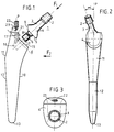
- Figure 1 is a schematic representation seen front view of a rod characteristic of the invention.
- Figure 2 is a side view of this rod, shown along the axis F2 perpendicular to the longitudinal axis P of the rod, while FIG. 3 is a view of top shown along the longitudinal axis F1 of the prosthetic neck.
- Figure 4 is a detailed representation of the assembly characteristic of the invention.
- Figure 5 is a schematic representation seen side of a rod characteristic of the invention according to another embodiment.
- Figure 6 is a representation of a detail of the proximal part of the rod conforming to that shown in Figure 5.
- Figure 7 is a schematic representation of the prosthetic neck conforming to the representation of the figure 5.
- Figure 8 is another representation of this pass prosthetic.
- Figure 9 is a schematic representation of the prosthetic neck at different inclinations.
- Figure 10 is a schematic representation representing different possible inclinations of the neck prosthetic with respect to the median plane of the stem.
- the rod according to the invention basically consists of two parts, namely a prosthetic neck designated by the general reference (1) and a rod proper designated by the general reference (10).
- the prosthetic neck (1) intended to protrude from the femur to be reinforced, comprises in order a head (2), slightly frustoconical, intended to receive by fitting a sphere not shown on which the acetabular cup rests.
- This frustoconical head (2) is connected in a known manner to a neck (3), then to a base (4), the base (5) of which is perpendicular to the axis F1 of the prosthetic neck (1).
- This base (5) has in its middle and directed towards the outside, a cylindrical fitting surface (6), orthogonal to the base (5).
- this bearing (6) can be slightly frustoconical (walrus cone from 3 to 5 °).
- the end (7) of this cylindrical seat (6) is slightly bevelled.
- this cylindrical bearing surface (6) has substantially at its middle an annular groove (8) in the shape of a V.
- the rod (10) comprises in known manner a proximal portion designated by the general reference (11), a distal portion designated by the general reference (12), and a tip (13).
- This rod (10) is intended to be inserted into the medullary canal of the femur to be reinforced.
- the rod (10) and more precisely the proximal portion (11) has, at the limit of the burial zone, designated by the general reference E , a base (15) parallel to the base (5) of the neck (1), therefore perpendicular to the axis F1 , so as to be complementary to this base (5).
- the base (5) of the rod has a cylindrical housing (16) (see Figure 4), into which is inserted side by side the scope of the fitting (6) and disposed next to it.
- the two complementary bases (5.15) each extend by a small inclined face respectively (9) and (17), parallel to the longitudinal axis of the rod (10), that is to say parallel to the plane P , so that these two bases (5,9; 15, 17) have a general asymmetrical V shape to form an anti-rotational stop.
- the upper part (20) of the proximal portion (11) has a threaded channel (21) parallel to the faces (9,17), therefore with the median plane P of the rod, intended to receive a screw (22), the end (23) teat shape to come engage in the groove (8), and more precisely to bear on one of the faces thereof, and thereby immobilize the prosthetic neck (1) in the rod (10).
- This channel (21) slightly protrudes from the burial zone (E) and is therefore easily accessible at surgeon.
- the angle ⁇ of the prosthetic neck (1) with respect to the median plane P of the stem is variable from one neck to the other, for example by five in five degrees and between plus and minus thirty degrees from this plane P.
- This angle ⁇ which varies by construction, thus allows the surgeon according to the positioning of the acetabulum, to choose the most suitable prosthetic neck (1).
- the angle ⁇ varies from five to five degrees in a range between plus and minus thirty degrees relative to the median plane P of the rod.
- the length of the prosthetic neck (1) is between thirty and fifty millimeters, and the angle ⁇ formed by the base (15) proximal with the longitudinal axis of the rod, is close to forty eight to fifty degrees .
- the prosthetic neck (1) comprises a base (5) completely flat and perpendicular to the angle F1 of the neck.
- This prosthetic neck comprises as means of attachment a morse cone (24) of slightly conical shape, intended to cooperate with a complementary recess (25) formed by the base (15) of the proximal part (11) of the rod, and in look of said morse cone when the neck is in place on the rod.
- the neck (1) also includes a through hole (30) located in the same plane as said walrus cone (24), and further located in the same plane as the median plane P of the rod (10).
- This obviously (30) is intended to allow insertion a locking screw (26), intended to cooperate with a corresponding obviously (32) arranged in the base of the proximal part (11) of the rod, and more precisely at the tapped lower end (28), intended to cooperate with the thread (27) of the end of the screw (26).
- the walrus cone (24) and the screw (26) are concurrent when the cone is in place on the rod, so on the one hand, reduce the size of the recesses corresponding to the level of the rod, and on the other hand, to reinforce the mechanical resistance of the rod in particular in flexion.
- the rod head (29) is retracted when the screw is in square. In this way, the prosthetic neck is prevented from forming cam during certain movements of the patient on which is set up the prosthesis.
- the prosthesis according to the invention is characterized by its simplicity, its ease of implementation, and by the does not weaken the bone to be strengthened.
- This multiplicity of adaptation is further accentuated by the fact that the length of the head (2) of the neck is variable.
- the mechanical resistance of the prostheses thus produced is finds greatly increased, especially for the efforts of shear and bending.
Description
L'invention concerne une tige fémorale perfectionnée pour prothèse de hanche.The invention relates to an improved femoral stem for hip prosthesis.
De manière connue, et pour l'essentiel, une tige fémorale pour prothèse de hanche comprend :
- tout d'abord, un col prothétique, destiné à dépasser du fémur et dont l'extrémité présente une tête généralement conique, destinée à recevoir une sphère sur laquelle s'appuie la cupule cotyloïdienne ;
- ensuite, une tige proprement dite, destinée à être insérée dans le fémur à renforcer, comportant une portion proximale raccordée au col prothétique, et une portion distale dont la pointe est engagée dans le canal médullaire du fémur.
- first, a prosthetic neck, intended to protrude from the femur and the end of which has a generally conical head, intended to receive a sphere on which the acetabular cup rests;
- then, a rod proper, intended to be inserted into the femur to be reinforced, comprising a proximal portion connected to the prosthetic neck, and a distal portion whose tip is engaged in the medullary canal of the femur.
Il est bien connu à ce jour de réaliser de telles tiges en une ou deux parties. On a par exemple décrit dans le document FR-A-2 366 005, une tige du type en question, réalisée en deux parties reliées par leur base, et dont la section de raccordement est sensiblement perpendiculaire à l'axe longitudinal de la tige proprement dite. Cette solution qui donne de bons résultats, présente toutefois l'inconvénient de nécessiter de creuser le grand trochanter pour placer l'embase du col prothétique. Or cette opération affaiblit le fémur.It is well known to date to carry out such rods in one or two parts. We have for example described in document FR-A-2 366 005, a rod of the question, carried out in two parts linked by their base, and whose connection section is substantially perpendicular to the longitudinal axis of the stem properly said. This solution which gives good results, presents however the disadvantage of needing to dig the large trochanter to place the base of the prosthetic neck. This operation weakens the femur.
Dans ce type de tige constituée de deux parties, ou même dans les tiges monobloc, lorsque la tige est insérée dans le canal médullaire du fémur, si le chirurgien s'aperçoit que la tête de la tige est mal orientée par rapport au cotyle, il doit modifier le positionnement de la tige dans le canal médullaire, ce qui n'est pas sans poser de problèmes, notamment lorsque la tige est fixée par ciment.In this type of rod made up of two parts, or even in one-piece rods, when the rod is inserted in the spinal canal of the femur, if the surgeon realizes that the stem head is misdirected by compared to the acetabulum, it must modify the positioning of the stem in the spinal canal, which is not without cause problems, especially when the rod is attached by cement.
Pour pallier ces inconvénients, on a suggéré dans le document EP-A-0 000 549, de ménager à l'embase du col une couronne dentée qui coopère avec une couronne femelle complémentaire disposée sur le haut de la tige. Cette solution implique également d'entailler le grand trochanter, conduisant une nouvelle fois à l'affaiblissement du fémur. To overcome these drawbacks, it was suggested in document EP-A-0 000 549, to spare at the base of the neck a toothed crown which cooperates with a female crown complementary disposed on the top of the rod. This solution also involves nicking the greater trochanter, again leading to the weakening of the femur.
Pour s'affranchir de ces inconvénients rédhibitoires, on a alors proposé par exemple dans le document FR-A-2 183 230 une tige fémorale en deux parties, dont le col prothétique est rapporté au niveau de la partie supérieure de la tige, et est fixé par la coopération d'une partie mâle issue dudit col prothétique, et d'un orifice complémentaire, ménagé dans la partie supérieure de la tige. Le col est solidarisé au moyen d'un joint fileté, dont l'une des extrémités est fourchue, ladite fourche entourant partiellement la partie mâle issue du col prothétique afin de permettre la solidarisation réversible du col au niveau de la tige. L'avantage d'une telle réalisation réside dans le fait qu'il n'est plus nécessaire de procéder à l'enlèvement de la tige prothétique lors du changement de prothèse, seul le corps prothétique pouvant être changé. Néanmoins, cette réalisation ne permet pas d'orienter à loisir le col prothétique selon un angle d'antéversion donné par rapport au plan général de la tige, compte tenu du système même de solidarisation du col sur la tige.To overcome these crippling disadvantages, we then proposed for example in document FR-A-2 183 230 a femoral stem in two parts, the prosthetic neck is reported at the top of the rod, and is fixed by the cooperation of a male part from said prosthetic neck, and an orifice complementary, formed in the upper part of the rod. The neck is secured by means of a threaded joint, one end of which is forked, said fork partially surrounding the male part from the prosthetic neck in order to allow reversible joining from the neck to the stem. The advantage of such an achievement lies in the fact that it is no longer necessary remove the prosthetic stem during prosthesis change, only the prosthetic body can to be changed. However, this achievement does not allow orient the prosthetic neck at an angle anteversion given in relation to the general plan of the rod, taking into account the very system of securing the neck on the stem.
Par ailleurs, afin de s'affranchir de l'inconvénient inhérent à la fragilisation du grand torchanter, lors de la mise en place de la tige au sein du canal médullaire, on a alors proposé, par exemple dans le document US-A-4 963 155, de prévoir une embase de raccordement non perpendiculaire à l'axe longitudinal de la tige. Cependant, la tige fémorale de la prothèse décrite dans ce document comporte également une superstructure prolongeant l'extrémité supérieure de la tige, allongeant le bras de levier constitué par le col, et augmentant de manière rédhibitoire les risques de luxation de l'articulutation de la hanche.Furthermore, in order to overcome the inconvenience inherent in the embrittlement of the large torchanter, during the placement of the rod within the canal medullary, we then proposed, for example in the document US-A-4,963,155, to provide a connection base not perpendicular to the longitudinal axis of the rod. However, the femoral stem of the prosthesis described in this document also includes a superstructure extending the upper end of the rod, extending the lever arm formed by the collar, and increasing by prohibitive way the risks of dislocation of the joint hip.
L'invention pallie ces différents inconvénients. Elle propose une tige du type en question, réalisée en deux partie distinctes, mais dans laquelle il n'est plus nécessaire d'entailler le grand trochanter pour la mise en place et l'orientation adéquate de la tige par rapport au cotyle, et d'autre part, dans laquelle, l'orientation donnée du cotyle par rapport à la tige s'obtient en sélectionnant le col prothétique approprié en fonction du positionnement de la tige dans le fémur.The invention overcomes these various drawbacks. It offers a rod of the type in question, produced in two separate parts, but in which it is no longer necessary to nick the greater trochanter for putting in place and the correct orientation of the rod relative to at the acetabulum, and on the other hand, in which, the orientation data of the acetabulum in relation to the stem is obtained by selecting the collar prosthetic appropriate according to the positioning of the rod in the femur.
Cette tige fémorale perfectionnée pour prothèse de hanche, réalisée en deux parties distinctes, respectivement :
- une tige proprement dite, destinée à être insérée dans le fémur à
renforcer, comprenant :
- une portion proximale raccordée à un col prothétique, et présentant une embase de raccordement audit col ;
- et une portion distale ;
- un col prothétique choisi parmi une pluralité de cols prothétiques, dont l'angle α par rapport au plan médian P de la tige varie et est compris entre plus et moins trente degrés, le col étant destiné à dépasser du fémur, dont l'extrémité reçoit une sphère, et dont la base présente une embase complémentaire de l'embase proximale de la tige,
- a rod proper, intended to be inserted into the femur to be reinforced, comprising:
- a proximal portion connected to a prosthetic neck, and having a base for connection to said neck;
- and a distal portion;
- a prosthetic neck chosen from a plurality of prosthetic necks, the angle α of which with respect to the median plane P of the stem varies and is between plus and minus thirty degrees, the neck being intended to protrude from the femur, the end of which receives a sphere, and the base of which has a base complementary to the proximal base of the rod,
En d'autres termes, l'invention consiste outre à ménager l'embase de raccordement col prothétique/tige dans un plan non perpendiculaire à l'axe du col prothétique, et à disposer l'embase de raccordement au niveau de la zone d'enfouissement, ce qui permet ainsi d'éviter d'entailler le grand trochanter, surtout à proposer une pluralité de cols prothétiques au praticien, cols dont l'angle par rapport au plan longitudinal de la tige est variable et permet ainsi de sélectionner ce col en fonction des nécessités, notamment d'implantation de la tige dan le fémur. In other words, the invention also consists in providing the base for prosthetic neck / stem connection in a plane not perpendicular to the axis of the prosthetic neck, and to have the connection base at the level of the burial zone, thus avoiding nicking the large trochanter, especially to offer a plurality of prosthetic necks to the practitioner, necks whose angle relative to the longitudinal plane of the rod is variable and thus allows to select this collar according to the needs, in particular implantation of the stem in the femur.
Dans une première forme d'exécution préférée, les moyens complémentaires de solidarisation sont constitués respectivement par une portée cylindrique d'emmanchement mâle, disposée sur la base du col, et par un logement cylindrique correspondant ménagé en regard dans l'embase de la tige, la portée mâle présentant un logement annulaire destiné à coopérer avec l'extrémité d'une vis d'immobilisation, ménagée à cet effet dans un logement filetée taillé dans le haut de la tige. De préférence, les deux embases complémentaires ont une forme générale en V asymétrique, à savoir une embase proprement dite, associée à une petite face inclinée, formant butée anti-rotatoire.In a first preferred embodiment, the additional means of securing are made up respectively by a cylindrical fitting surface male, arranged on the base of the neck, and by a housing corresponding cylindrical opposite in the base of the stem, the male bearing having an annular housing intended to cooperate with the end of a screw immobilization, made for this purpose in a dwelling threaded cut at the top of the rod. Preferably, the two complementary bases have a general shape in asymmetrical V, namely a base itself, associated with a small inclined face, forming an anti-rotational stop.
Dans une autre forme d'éxécution de l'invention, l'embase du col prothétique est totalement plane, et les moyens de solidarisation sont constitués par :
- un cone morse émergeant perpendiculairement de l'embase du col prothétique, destiné à coopérer avec un logement de forme et de dimension complémentaires réalisé en regard dans l'embase de la tige ;
- une vis de verrouillage, destinée à venir s'insérer dans un évidement ménagé à cet effet au niveau de l'embase dudit col, et à venir à coopérer avec un orifice taraudé de manière complémentaire ménagé dans l'embase de la tige.
- a walrus cone emerging perpendicularly from the base of the prosthetic neck, intended to cooperate with a housing of complementary shape and dimension made opposite in the base of the rod;
- a locking screw, intended to be inserted into a recess provided for this purpose at the base of said neck, and to come to cooperate with a tapped orifice in a complementary manner formed in the base of the rod.
Avantageusement la vis de verrouillage et le cone sont disposés dans un même plan, lui-même coplanaire avec le plan médian de la tige. En outre, cette vis et ce cone forment entre eux un angle compris entre 10 et 20°, et avantageusement 15°, de sorte qu'ils concourent au niveau de la partie proximale de la tige.Advantageously the locking screw and the cone are arranged in the same plane, itself coplanar with the median plane of the stem. In addition, this screw and this cone form between them an angle between 10 and 20 °, and advantageously 15 °, so that they compete at the level of the proximal part of the stem.
La manière dont l'invention peut être réalisée et les avantages qui en découlent ressortiront des exemples de réalisation qui suivent donnés à titre indicatif et non limitatif à l'appui des figures annexées. The manner in which the invention can be carried out and the resulting benefits will emerge from the examples of realization which follow given for information only and not limiting in support of the appended figures.
La figure 1 est une représentation schématique vue de face d'une tige caractéristique de l'invention.Figure 1 is a schematic representation seen front view of a rod characteristic of the invention.
La figure 2 est une vue de côté de cette tige, montrée suivant l'axe F2 perpendiculaire à l'axe longitudinal P de la tige, alors que la figure 3 est une vue de dessus montrée suivant l'axe F1 longitudinal du col prothétique.Figure 2 is a side view of this rod, shown along the axis F2 perpendicular to the longitudinal axis P of the rod, while FIG. 3 is a view of top shown along the longitudinal axis F1 of the prosthetic neck.
La figure 4 est une représentation détaillée de l'assemblage caractéristique de l'invention.Figure 4 is a detailed representation of the assembly characteristic of the invention.
La figure 5 est une représentation schématique vue de côté d'une tige caractéristique de l'invention selon une autre forme de réalisation.Figure 5 is a schematic representation seen side of a rod characteristic of the invention according to another embodiment.
La figure 6 est une représentation d'un détail de la partie proximale de la tige conforme à celle représentée sur la figure 5.Figure 6 is a representation of a detail of the proximal part of the rod conforming to that shown in Figure 5.
La figure 7 est une représentation schématique du col prothétique conforme à la représentation de la figure 5.Figure 7 is a schematic representation of the prosthetic neck conforming to the representation of the figure 5.
La figure 8 est une autre représentation de ce col prothétique.Figure 8 is another representation of this pass prosthetic.
La figure 9 est une représentation schématique du col prothétique selon différentes inclinaisons.Figure 9 is a schematic representation of the prosthetic neck at different inclinations.
La figure 10 est une représentation schématique représentant différentes inclinaisons possibles du col prothétique par rapport au plan médian de la tige.Figure 10 is a schematic representation representing different possible inclinations of the neck prosthetic with respect to the median plane of the stem.
En se référant aux figures, la tige selon l'invention comprend essentiellement deux parties, à savoir un col prothétique désigné par la référence générale (1) et une tige proprement dite désignée par la référence générale (10).Referring to the figures, the rod according to the invention basically consists of two parts, namely a prosthetic neck designated by the general reference (1) and a rod proper designated by the general reference (10).
Le col prothétique (1), destiné à dépasser du fémur à renforcer, comprend dans l'ordre une tête (2), légèrement tronconique, destinée à recevoir par emmanchement une sphère non représentée sur laquelle s'appuie la cupule cotyloïdienne. Cette tête tronconique (2) est raccordée de manière connue à un col (3), puis à une base (4), dont l'embase (5) est perpendiculaire à l'axe F1 du col prothétique (1). Cette embase (5) présente en son milieu et dirigée vers l'extérieur, une portée cylindrique d'emmanchement (6), orthogonale à l'embase (5). Dans une variante,cette portée (6) peut être légèrement tronconique (cone de morse de 3 à 5°). L'extrémité (7) de cette portée cylindrique (6) est légèrement biseautée.The prosthetic neck (1), intended to protrude from the femur to be reinforced, comprises in order a head (2), slightly frustoconical, intended to receive by fitting a sphere not shown on which the acetabular cup rests. This frustoconical head (2) is connected in a known manner to a neck (3), then to a base (4), the base (5) of which is perpendicular to the axis F1 of the prosthetic neck (1). This base (5) has in its middle and directed towards the outside, a cylindrical fitting surface (6), orthogonal to the base (5). In a variant, this bearing (6) can be slightly frustoconical (walrus cone from 3 to 5 °). The end (7) of this cylindrical seat (6) is slightly bevelled.
Selon une autre caractéristique de l'invention, cette portée cylindrique (6) présente sensiblement en son milieu une gorge annulaire (8) en forme de V.According to another characteristic of the invention, this cylindrical bearing surface (6) has substantially at its middle an annular groove (8) in the shape of a V.
La tige (10) comprend de manière connue une portion proximale désignée par la référence générale (11), une portion distale désignée par la référence générale (12), et une pointe (13). Cette tige (10) est destinée à être insérée dans le canal médullaire du fémur à renforcer. Selon une caractéristique de l'invention, la tige (10) et plus exactement la portion proximale (11) présente, à la limite de la zone d'enfouissement, désignée par la référence générale E, une embase (15) parallèle à l'embase (5) du col (1), donc perpendiculaire à l'axe F1, de manière à être complémentaire de cette embase (5).The rod (10) comprises in known manner a proximal portion designated by the general reference (11), a distal portion designated by the general reference (12), and a tip (13). This rod (10) is intended to be inserted into the medullary canal of the femur to be reinforced. According to a characteristic of the invention, the rod (10) and more precisely the proximal portion (11) has, at the limit of the burial zone, designated by the general reference E , a base (15) parallel to the base (5) of the neck (1), therefore perpendicular to the axis F1 , so as to be complementary to this base (5).
Selon une autre caractéristique de l'invention, l'embase (5) de la tige présente un logement cylindrique (16) (voir figure 4), dans lequel s'insère cote pour cote la portée de l'emmanchement (6) et disposé en regard de celle-ci. Les deux embases complémentaires (5,15) se prolongent chacune par une petite face inclinée respectivement (9) et (17), parallèles à l'axe longitudinal de la tige (10), c'est-à-dire parallèles au plan P, de manière à ce que ces deux embases (5,9; 15, 17) aient une forme générale en V asymétrique pour former butée anti-rotatoire. According to another characteristic of the invention, the base (5) of the rod has a cylindrical housing (16) (see Figure 4), into which is inserted side by side the scope of the fitting (6) and disposed next to it. The two complementary bases (5.15) each extend by a small inclined face respectively (9) and (17), parallel to the longitudinal axis of the rod (10), that is to say parallel to the plane P , so that these two bases (5,9; 15, 17) have a general asymmetrical V shape to form an anti-rotational stop.
La partie supérieure (20) de la portion proximale (11) présente un canal fileté (21) parallèle aux faces (9,17), donc avec le plan médian P de la tige, destiné à recevoir une vis (22) dont l'extrémité (23) forme têton pour venir s'engager dans la gorge (8), et plus exactement pour prendre appui sur une des faces de celle-ci, et par là immobiliser le col prothétique (1) dans la tige (10).The upper part (20) of the proximal portion (11) has a threaded channel (21) parallel to the faces (9,17), therefore with the median plane P of the rod, intended to receive a screw (22), the end (23) teat shape to come engage in the groove (8), and more precisely to bear on one of the faces thereof, and thereby immobilize the prosthetic neck (1) in the rod (10).
Ce canal (21) dépasse légèrement de la zone d'enfouissement (E) et est donc facilement accessible au chirurgien.This channel (21) slightly protrudes from the burial zone (E) and is therefore easily accessible at surgeon.
Selon une autre caractéristique essentielle de l'invention (voir figure 2), l'angle α du col prothétique (1) par rapport au plan médian P de la tige est variable d'un col par rapport à l'autre, par exemple de cinq en cinq degrés et entre plus et moins trente degrés par rapport à ce plan P. Cet angle α qui varie par construction, permet ainsi au chirurgien en fonction du positionnement du cotyle, de choisir le col prothétique (1) le plus approprié.According to another essential characteristic of the invention (see FIG. 2), the angle α of the prosthetic neck (1) with respect to the median plane P of the stem is variable from one neck to the other, for example by five in five degrees and between plus and minus thirty degrees from this plane P. This angle α which varies by construction, thus allows the surgeon according to the positioning of the acetabulum, to choose the most suitable prosthetic neck (1).
Le fait que les deux embases de raccordement (5,15) complémentaires soient disposées à la limite, mais juste en-dessus de la zone d'enfouissement E, permet avantageusement d'éviter d'entailler le grand trochanter. Le fait que les deux parties (1,10) soient solidarisées par un système gorge (8)/tenon (23), assure à l'ensemble une excellente tenue. Le fait que le col prothétique (1) soit incliné par rapport au plan médian P de la tige (10), permet d'insérer la tige (10) dans le canal médullaire, puis d'adapter selon le besoin et l'architecture le positionnement du col (1) par rapport au cotyle, et ce quelle que soit l'orientation de la cavité cotyloïdienne. The fact that the two complementary connection bases (5,15) are arranged at the limit, but just above the burial zone E , advantageously makes it possible to avoid nicking the greater trochanter. The fact that the two parts (1.10) are secured by a groove (8) / tenon (23) system, provides the assembly with excellent hold. The fact that the prosthetic neck (1) is inclined relative to the median plane P of the rod (10), makes it possible to insert the rod (10) into the medullary canal, then to adapt according to need and architecture the positioning of the neck (1) relative to the acetabulum, regardless of the orientation of the acetabular cavity.
En outre, comme la prothèse est réalisée en deux parties distinctes, lors de la mise en place, le chirurgien n'est plus gêné par le col (1) qui est fixé ultérieurement grâce à l'assemblage vis (22)/tenon (23)/gorge (8).In addition, as the prosthesis is made in two separate parts, during placement, the surgeon no longer bothered by the collar (1) which is fixed later thanks to the screw (22) / tenon (23) / groove (8) assembly.
Avantageusement, en pratique, comme déjà dit, l'angle α varie de cinq en cinq degrés dans une fourchette comprise entre plus et moins trente degrés par rapport au plan médian P de la tige. De même, la longueur du col prothétique (1) est comprise entre trente et cinquante millimètres, et l'angle β formé par l'embase (15) proximale avec l'axe longitudinal de la tige, est voisin de quarante huit à cinquante degrés.Advantageously, in practice, as already said, the angle α varies from five to five degrees in a range between plus and minus thirty degrees relative to the median plane P of the rod. Similarly, the length of the prosthetic neck (1) is between thirty and fifty millimeters, and the angle β formed by the base (15) proximal with the longitudinal axis of the rod, is close to forty eight to fifty degrees .
Selon une seconde forme de réalisation plus particulièrement représentée dans les figures 5 à 10, le col prothétique (1), comporte une embase (5) totalement plane et perpendiculaire à l'angle F1 du col. Ce col prothétique comporte comme moyen de solidarisation un cone morse (24) de forme légèrement conique, destiné à coopérer avec un évidemment complémentaire (25) ménagé de l'embase (15) de la partie proximale (11) de la tige, et en regard dudit cone morse lorsque le col est en place sur la tige.According to a second embodiment more particularly shown in Figures 5 to 10, the prosthetic neck (1) comprises a base (5) completely flat and perpendicular to the angle F1 of the neck. This prosthetic neck comprises as means of attachment a morse cone (24) of slightly conical shape, intended to cooperate with a complementary recess (25) formed by the base (15) of the proximal part (11) of the rod, and in look of said morse cone when the neck is in place on the rod.
Corrélativement, le col (1) comporte également un orifice (30) traversant situé dans le même plan que ledit cone morse (24), et en outre situé dans le même plan que le plan médian P de la tige (10).Correlatively, the neck (1) also includes a through hole (30) located in the same plane as said walrus cone (24), and further located in the same plane as the median plane P of the rod (10).
Cet évidemment (30) est destiné à permettre l'insertion d'une vis de verrouillage (26), destinée à coopérer avec un évidemment correspondant (32) ménagé dans l'embase de la partie proximale (11) de la tige, et plus précisément à l'extrémité inférieure (28) taraudée, destinée à coopérer avec le filetage (27) de l'extrémité de la vis (26). This obviously (30) is intended to allow insertion a locking screw (26), intended to cooperate with a corresponding obviously (32) arranged in the base of the proximal part (11) of the rod, and more precisely at the tapped lower end (28), intended to cooperate with the thread (27) of the end of the screw (26).
Selon une caractéristique avantageuse de l'invention, le cone morse (24) et la vis (26) sont concourants lorsque le cone est en place sur la tige, de telle sorte, à d'une part, réduire l'encombrement des évidemments correspondants au niveau de la tige, et d'autre part, à renforcer la résistance mécanique de la tige notamment en flexion. Comme on l'a représenté sur la figure 5, la tête de la tige (29) est escamoté lorsque la vis est en place. De la sorte, on évite au col prothétique de former came lors de certains mouvements du patient sur lequel est mis en place la prothèse.According to an advantageous characteristic of the invention, the walrus cone (24) and the screw (26) are concurrent when the cone is in place on the rod, so on the one hand, reduce the size of the recesses corresponding to the level of the rod, and on the other hand, to reinforce the mechanical resistance of the rod in particular in flexion. As shown in Figure 5, the rod head (29) is retracted when the screw is in square. In this way, the prosthetic neck is prevented from forming cam during certain movements of the patient on which is set up the prosthesis.
Ce système de fixation s'avère particulièrement avantageux. En effet, tout d'abord la coopération du cone morse (24) avec l'évidemment complémentaire (25) ménagé dans la tige est autobloquant puisqu'il y a adhérence du cone sur cet évidemment. En outre, cette adhérence est verrouillée au moyen de la vis (26) munie du filetage (27).This fastening system is particularly advantageous. First of all, the cooperation of the Morse cone (24) with obviously complementary (25) formed in the rod is self-locking since there is adhesion of the cone on this obviously. In addition, this adhesion is locked by means of the screw (26) provided with the thread (27).
Ces différents résultats se traduisent par une solidarisation plus sûre du col sur la tige, augmentant la résistance aux efforts de cisaillement et de flexion, compte tenu d'un tenon à section plus importante, la vis de verrouillage participant également à la tenue mécanique des différentes pièces.These different results translate into a safer joining of the collar on the rod, increasing resistance to shear and bending forces, taking into account a lug with a larger section, the screw locking device also participating in mechanical strength of the different rooms.
La prothèse selon l'invention se caractérise par sa simplicité, sa facilité de mise en oeuvre, et par le fait qu'elle n'affaiblit pas l'os à renforcer. En outre, compte tenu du grand nombre de cols prothétiques adaptables sur une tige donnée, cela confère au praticien une très grande modularité, favorisant ainsi l'adaptation de la prothèse au patient. Cette multiplicité d'adaptation est en outre accentuée par le fait que la longueur de la tête (2) du col est variable. Enfin, compte tenu de la structure même de l'ensemble tige-col, la résistance mécanique des prothèses ainsi réalisées se trouve grandement accrue, notamment pour les efforts de cisaillement et de flexion.The prosthesis according to the invention is characterized by its simplicity, its ease of implementation, and by the does not weaken the bone to be strengthened. In addition, given the large number of adaptable prosthetic necks on a given rod, this gives the practitioner very high modularity, thus promoting adaptation from the prosthesis to the patient. This multiplicity of adaptation is further accentuated by the fact that the length of the head (2) of the neck is variable. Finally, taking into account the very structure of the stem-neck assembly, the mechanical resistance of the prostheses thus produced is finds greatly increased, especially for the efforts of shear and bending.
Claims (7)
- Improved femoral stem for a hip prosthesis, made up of two separate parts, namely:the said shoulder (15) for connecting the stem (10) to the said prosthetic neck (1) being situated in a plane not perpendicular to the longitudinal axis of the said stem (10), and the two complementary shoulders (5, 15) having complementary means (4, 6, 7, 8, 16, 17, 18, 24-31) for securing the neck (1) on the stem (10).a stem proper (10) intended to be inserted into the femur to be strengthened, comprising:a proximal portion (11) connected to a prosthetic neck (1), and having a shoulder (15) for connection to the said neck (1);and a distal portion;a prosthetic neck chosen from among a plurality of prosthetic necks (1), of which the angle α in relation to the mid-plane P of the stem (10) varies and is between plus and minus thirty degrees, the neck being intended to protrude from the femur, and of which the end (2) receives a ball, and of which the base (4) has a shoulder (5) which complements the proximal shoulder (15) of the stem (10),
- Femoral stem according to Claim 1, characterized in that the complementary securing means consist, respectively, of a cylindrical bearing surface (6), for male engagement, arranged on the shoulder (5) of the neck (1), and of a complementary cylindrical seat (16) formed opposite in the shoulder (5) of the stem (10), the male bearing surface (6) having an annular seat (8) intended to cooperate with the end (23) of a fixing screw (22) formed in a threaded seat (21) cut in the top (20) of the stem (10).
- Improved femoral stem according to one of Claims 1 and 2, characterized in that the two complementary shoulders (5, 15) have the general shape of an asymmetrical V and comprise a large shoulder (5, 15) proper, together with a small inclined face (9, 17) parallel to the longitudinal axis of the stem, in such a way as to form an anti-rotation stop.
- Femoral stem according to one of Claims 1 to 3, characterized in that the angle α of the prosthetic neck (1) in relation to the mid-plane P of the stem (10) varies by five degrees at a time from one neck (1) to another of the plurality of prosthetic necks from among which the said neck is chosen.
- Femoral stem according to Claim 1, characterized in that the shoulder (5) of the prosthetic neck (1) is totally plane, and in that the securing means consist:of a Morse cone (24) protruding perpendicularly from the shoulder (5) of the neck (1) and intended to cooperate with a seat (25), of complementary shape and size, formed in the proximal part (11) of the stem (10), and opening out at the level of the shoulder (15) thereof opposite the said cone (24);of a locking screw (26) intended to be inserted in a recess (30) formed for this purpose at the level of the shoulder (5) of the neck (1) and intended to cooperate with a complementary tapped orifice (28) formed in the proximal part (11) of the stem (10) and opening out at the level of the shoulder (15).
- Femoral stem according to Claim 5, characterized in that the locking screw (26) and the Morse cone (24) are situated in the same plane, itself coplanar with the mid-plane P of the stem (10).
- Femoral stem according to one of Claims 5 and 6, characterized in that the locking screw (26) and the Morse cone (24) run together, the angle which they define being between 10 and 20 degrees.
Applications Claiming Priority (2)
| Application Number | Priority Date | Filing Date | Title |
|---|---|---|---|
| FR9014106 | 1990-11-06 | ||
| FR9014106A FR2668702B1 (en) | 1990-11-06 | 1990-11-06 | PERFECTED FEMALE ROD FOR HIP PROSTHESIS. |
Publications (2)
| Publication Number | Publication Date |
|---|---|
| EP0485311A1 EP0485311A1 (en) | 1992-05-13 |
| EP0485311B1 true EP0485311B1 (en) | 1998-08-12 |
Family
ID=9402150
Family Applications (1)
| Application Number | Title | Priority Date | Filing Date |
|---|---|---|---|
| EP19910420391 Expired - Lifetime EP0485311B1 (en) | 1990-11-06 | 1991-11-05 | Stem for hip prosthesis |
Country Status (4)
| Country | Link |
|---|---|
| EP (1) | EP0485311B1 (en) |
| DE (1) | DE69129969T2 (en) |
| ES (1) | ES2119766T3 (en) |
| FR (1) | FR2668702B1 (en) |
Cited By (1)
| Publication number | Priority date | Publication date | Assignee | Title |
|---|---|---|---|---|
| DE102005006316A1 (en) * | 2005-02-11 | 2006-08-24 | Nowakowski, Andrej, Dr. med. Dipl.-Ing.(FH) | Hip endoprosthesis |
Families Citing this family (18)
| Publication number | Priority date | Publication date | Assignee | Title |
|---|---|---|---|---|
| FR2701836B1 (en) * | 1993-02-22 | 1998-01-30 | Medinov Sa | Modular neck for femoral stem of hip prosthesis. |
| FR2723308B1 (en) | 1994-08-02 | 1996-12-13 | Impact | ADVANCED HIP PROSTHESIS |
| FR2753081B1 (en) * | 1996-09-11 | 1999-03-05 | Daniel Noyer | HIP FEMALE PROSTHESIS WITH ANTEPULSED FLANGE |
| GB9620998D0 (en) * | 1996-10-09 | 1996-11-27 | Minnesota Mining & Mfg | Shoulder prosthesis |
| FR2760966B1 (en) * | 1997-03-21 | 1999-07-23 | Merck Biomaterial France | HIP PROSTHESIS |
| GB9707371D0 (en) | 1997-04-11 | 1997-05-28 | Minnesota Mining & Mfg | A modular humeral prosthesis |
| US6120544A (en) * | 1997-05-16 | 2000-09-19 | Eska Implants Gmbh & Co. | Femur endoprosthesis for articial hip joint |
| US7189261B2 (en) | 1998-04-03 | 2007-03-13 | Smith & Nephew, Inc. | Modular humeral prosthesis and method |
| GB9828084D0 (en) * | 1998-12-18 | 1999-02-17 | Benoist Girard & Cie | Femoral component |
| IT1316060B1 (en) * | 1999-07-27 | 2003-03-28 | Tecnomeccanica Srl | ANTI-LUXURY BILATERAL HIP PROSTHESIS. |
| DE10021527C1 (en) * | 2000-05-03 | 2001-12-06 | Aesculap Ag & Co Kg | Femoral neck prosthesis |
| US7097663B1 (en) | 2001-12-17 | 2006-08-29 | Smith & Nephew, Inc. | Modular prosthesis system with novel locking mechanism |
| DE10252123B3 (en) * | 2002-11-05 | 2004-07-22 | Eska Implants Gmbh & Co. | Set for creating an artificial hip joint |
| DE102004038281B3 (en) * | 2004-08-03 | 2006-05-11 | Endoplant Gmbh | Femoral neck prosthesis for an artificial hip joint comprises an implantable shaft which is curved and has a proximal region with a polygonal cross-section and a distal region with a round cross-section |
| CA2646401C (en) * | 2006-03-20 | 2014-07-15 | Lawrence D. Dorr | Prosthetic hip implants |
| FR2922436B1 (en) * | 2007-10-17 | 2010-01-08 | Levon Doursounian | FEMORAL ELEMENT OF HIP PROSTHESIS, AND TOTAL HIP PROSTHESIS COMPRISING IT. |
| US9101477B2 (en) * | 2011-10-17 | 2015-08-11 | Thomas Hatton McCoy | Anterior offset component for total hip replacement |
| FR2985172B1 (en) * | 2012-01-04 | 2014-02-14 | Wilko Fockens | FRACTURE SHOULDER PROSTHESIS WITH RETENTIVE AND UNIVERSAL ASSEMBLY MECHANISM |
Family Cites Families (7)
| Publication number | Priority date | Publication date | Assignee | Title |
|---|---|---|---|---|
| SU440014A1 (en) * | 1972-05-04 | 1978-08-05 | Саратовский государственный медицинский институт | Endoprosthesis of proximal end of thighbone |
| FR2366005A2 (en) * | 1976-07-28 | 1978-04-28 | Mahay Cie | Hip joint replacement prosthesis - has separate socket portion fixed to hip bone by screw at junction rebated into top of bone |
| DE2734249A1 (en) * | 1977-07-29 | 1979-02-08 | Bayer Ag | THIGH NECK PROSTHESIS |
| US4608055A (en) * | 1984-01-12 | 1986-08-26 | Mayo Foundation | Femoral component for hip prosthesis |
| FR2596642B1 (en) * | 1986-04-04 | 1988-06-24 | Demeulenaere Claude | HIP PROSTHESIS |
| FR2640497B1 (en) * | 1988-12-19 | 1997-10-03 | Mesguich Alain | FEMALE IMPLANT FOR HIP PROSTHESIS |
| US4963155A (en) * | 1989-08-30 | 1990-10-16 | Zimmer, Inc. | Attachment mechanism for modular surgical products |
-
1990
- 1990-11-06 FR FR9014106A patent/FR2668702B1/en not_active Expired - Fee Related
-
1991
- 1991-11-05 ES ES91420391T patent/ES2119766T3/en not_active Expired - Lifetime
- 1991-11-05 EP EP19910420391 patent/EP0485311B1/en not_active Expired - Lifetime
- 1991-11-05 DE DE1991629969 patent/DE69129969T2/en not_active Expired - Fee Related
Cited By (1)
| Publication number | Priority date | Publication date | Assignee | Title |
|---|---|---|---|---|
| DE102005006316A1 (en) * | 2005-02-11 | 2006-08-24 | Nowakowski, Andrej, Dr. med. Dipl.-Ing.(FH) | Hip endoprosthesis |
Also Published As
| Publication number | Publication date |
|---|---|
| FR2668702B1 (en) | 1995-06-09 |
| ES2119766T3 (en) | 1998-10-16 |
| FR2668702A1 (en) | 1992-05-07 |
| DE69129969T2 (en) | 1998-12-24 |
| EP0485311A1 (en) | 1992-05-13 |
| DE69129969D1 (en) | 1998-09-17 |
Similar Documents
| Publication | Publication Date | Title |
|---|---|---|
| EP0485311B1 (en) | Stem for hip prosthesis | |
| EP0190981B1 (en) | Primary fixation total hip prosthesis | |
| EP0259420B1 (en) | Prosthesis cupula | |
| EP0879031B1 (en) | Non-dislocatable low-wear hip prosthesis | |
| EP0038897B1 (en) | Non cemented intramedullary prosthesis for a hip joint | |
| FR2575383A1 (en) | Prosthesis for synovial joint | |
| EP0797964A1 (en) | Assembly of elements for the formation of a total hip prosthesis | |
| FR2860425A1 (en) | HUMERAL IMPLANT FOR PROSTHESIS OF THE SHOULDER | |
| WO1991018560A1 (en) | Hip prosthesis | |
| EP0711534B1 (en) | Femoral stem for prosthesis | |
| FR2647669A1 (en) | Anatomical hip prosthesis | |
| FR2606273A1 (en) | Improved joint prosthesis | |
| FR2683717A1 (en) | Femoral stem for total hip prosthesis | |
| FR2903882A1 (en) | Insert for cotyloidal implant, has hemispherical outer surface with centre separated with respect to centre of hemispherical inner surface along axis of revolution of outer surface in direction of opening of insert | |
| EP0241361A1 (en) | Hip prosthesis | |
| FR2575384A1 (en) | Femoral prosthesis and corresponding accessory | |
| EP0354142B1 (en) | Stem for a total hip prosthesis | |
| FR2626169A1 (en) | Hip prosthesis | |
| FR2751528A1 (en) | Artificial hip joint prosthesis | |
| FR2799115A1 (en) | Modular shank for hip prosthesis comprises medullary pin with cylindrical surface for thrust member, stops and support | |
| FR2681239A1 (en) | Shaft for total hip prosthesis | |
| FR2721201A1 (en) | Cotyloid prosthesis | |
| FR2788429A1 (en) | Hip prosthesis femoral shank assembly has conical socket for shank close to outer edge of metaphysis component to allow for adjustment | |
| FR2760966A1 (en) | HIP PROSTHESIS | |
| FR2827155A1 (en) | Hip prosthesis femoral shank has pairs of cavities in inner face of metaphysis section |
Legal Events
| Date | Code | Title | Description |
|---|---|---|---|
| PUAI | Public reference made under article 153(3) epc to a published international application that has entered the european phase |
Free format text: ORIGINAL CODE: 0009012 |
|
| AK | Designated contracting states |
Kind code of ref document: A1 Designated state(s): BE CH DE ES FR GB IT LI |
|
| 17P | Request for examination filed |
Effective date: 19920727 |
|
| 17Q | First examination report despatched |
Effective date: 19931112 |
|
| GRAG | Despatch of communication of intention to grant |
Free format text: ORIGINAL CODE: EPIDOS AGRA |
|
| RAP1 | Party data changed (applicant data changed or rights of an application transferred) |
Owner name: MERCK BIOMATERIAL FRANCE |
|
| APAB | Appeal dossier modified |
Free format text: ORIGINAL CODE: EPIDOS NOAPE |
|
| APAB | Appeal dossier modified |
Free format text: ORIGINAL CODE: EPIDOS NOAPE |
|
| APAD | Appeal reference recorded |
Free format text: ORIGINAL CODE: EPIDOS REFNE |
|
| APAB | Appeal dossier modified |
Free format text: ORIGINAL CODE: EPIDOS NOAPE |
|
| APAB | Appeal dossier modified |
Free format text: ORIGINAL CODE: EPIDOS NOAPE |
|
| GRAG | Despatch of communication of intention to grant |
Free format text: ORIGINAL CODE: EPIDOS AGRA |
|
| GRAG | Despatch of communication of intention to grant |
Free format text: ORIGINAL CODE: EPIDOS AGRA |
|
| GRAH | Despatch of communication of intention to grant a patent |
Free format text: ORIGINAL CODE: EPIDOS IGRA |
|
| GRAH | Despatch of communication of intention to grant a patent |
Free format text: ORIGINAL CODE: EPIDOS IGRA |
|
| RAP1 | Party data changed (applicant data changed or rights of an application transferred) |
Owner name: MERCK BIOMATERIAL FRANCE |
|
| GRAA | (expected) grant |
Free format text: ORIGINAL CODE: 0009210 |
|
| AK | Designated contracting states |
Kind code of ref document: B1 Designated state(s): BE CH DE ES FR GB IT LI |
|
| PG25 | Lapsed in a contracting state [announced via postgrant information from national office to epo] |
Ref country code: IT Free format text: LAPSE BECAUSE OF FAILURE TO SUBMIT A TRANSLATION OF THE DESCRIPTION OR TO PAY THE FEE WITHIN THE PRESCRIBED TIME-LIMIT;WARNING: LAPSES OF ITALIAN PATENTS WITH EFFECTIVE DATE BEFORE 2007 MAY HAVE OCCURRED AT ANY TIME BEFORE 2007. THE CORRECT EFFECTIVE DATE MAY BE DIFFERENT FROM THE ONE RECORDED. Effective date: 19980812 |
|
| REG | Reference to a national code |
Ref country code: CH Ref legal event code: EP |
|
| REF | Corresponds to: |
Ref document number: 69129969 Country of ref document: DE Date of ref document: 19980917 |
|
| REG | Reference to a national code |
Ref country code: ES Ref legal event code: FG2A Ref document number: 2119766 Country of ref document: ES Kind code of ref document: T3 |
|
| GBT | Gb: translation of ep patent filed (gb section 77(6)(a)/1977) |
Effective date: 19981014 |
|
| PGFP | Annual fee paid to national office [announced via postgrant information from national office to epo] |
Ref country code: ES Payment date: 19981116 Year of fee payment: 8 |
|
| PGFP | Annual fee paid to national office [announced via postgrant information from national office to epo] |
Ref country code: CH Payment date: 19981119 Year of fee payment: 8 |
|
| PGFP | Annual fee paid to national office [announced via postgrant information from national office to epo] |
Ref country code: BE Payment date: 19981210 Year of fee payment: 8 |
|
| PLBE | No opposition filed within time limit |
Free format text: ORIGINAL CODE: 0009261 |
|
| STAA | Information on the status of an ep patent application or granted ep patent |
Free format text: STATUS: NO OPPOSITION FILED WITHIN TIME LIMIT |
|
| 26N | No opposition filed | ||
| PGFP | Annual fee paid to national office [announced via postgrant information from national office to epo] |
Ref country code: GB Payment date: 19991029 Year of fee payment: 9 |
|
| PG25 | Lapsed in a contracting state [announced via postgrant information from national office to epo] |
Ref country code: ES Free format text: LAPSE BECAUSE OF NON-PAYMENT OF DUE FEES Effective date: 19991106 |
|
| PGFP | Annual fee paid to national office [announced via postgrant information from national office to epo] |
Ref country code: DE Payment date: 19991115 Year of fee payment: 9 |
|
| PG25 | Lapsed in a contracting state [announced via postgrant information from national office to epo] |
Ref country code: LI Free format text: LAPSE BECAUSE OF NON-PAYMENT OF DUE FEES Effective date: 19991130 Ref country code: CH Free format text: LAPSE BECAUSE OF NON-PAYMENT OF DUE FEES Effective date: 19991130 Ref country code: BE Free format text: LAPSE BECAUSE OF NON-PAYMENT OF DUE FEES Effective date: 19991130 |
|
| BERE | Be: lapsed |
Owner name: MERCK BIOMATERIAL FRANCE Effective date: 19991130 |
|
| REG | Reference to a national code |
Ref country code: CH Ref legal event code: PL |
|
| PG25 | Lapsed in a contracting state [announced via postgrant information from national office to epo] |
Ref country code: GB Free format text: LAPSE BECAUSE OF NON-PAYMENT OF DUE FEES Effective date: 20001105 |
|
| GBPC | Gb: european patent ceased through non-payment of renewal fee |
Effective date: 20001105 |
|
| PG25 | Lapsed in a contracting state [announced via postgrant information from national office to epo] |
Ref country code: DE Free format text: LAPSE BECAUSE OF NON-PAYMENT OF DUE FEES Effective date: 20010801 |
|
| PGFP | Annual fee paid to national office [announced via postgrant information from national office to epo] |
Ref country code: FR Payment date: 20031127 Year of fee payment: 13 |
|
| REG | Reference to a national code |
Ref country code: ES Ref legal event code: FD2A Effective date: 20001214 |
|
| PG25 | Lapsed in a contracting state [announced via postgrant information from national office to epo] |
Ref country code: FR Free format text: LAPSE BECAUSE OF NON-PAYMENT OF DUE FEES Effective date: 20050729 |
|
| REG | Reference to a national code |
Ref country code: FR Ref legal event code: ST |
|
| APAH | Appeal reference modified |
Free format text: ORIGINAL CODE: EPIDOSCREFNO |