EP0484629B1 - Mesure de fréquence basée sur un nombre constant d'événements avec un circuit inverse rapide - Google Patents
Mesure de fréquence basée sur un nombre constant d'événements avec un circuit inverse rapide Download PDFInfo
- Publication number
- EP0484629B1 EP0484629B1 EP91110690A EP91110690A EP0484629B1 EP 0484629 B1 EP0484629 B1 EP 0484629B1 EP 91110690 A EP91110690 A EP 91110690A EP 91110690 A EP91110690 A EP 91110690A EP 0484629 B1 EP0484629 B1 EP 0484629B1
- Authority
- EP
- European Patent Office
- Prior art keywords
- output
- producing
- counter
- time
- signal
- Prior art date
- Legal status (The legal status is an assumption and is not a legal conclusion. Google has not performed a legal analysis and makes no representation as to the accuracy of the status listed.)
- Expired - Lifetime
Links
Images


Classifications
-
- G—PHYSICS
- G01—MEASURING; TESTING
- G01R—MEASURING ELECTRIC VARIABLES; MEASURING MAGNETIC VARIABLES
- G01R23/00—Arrangements for measuring frequencies; Arrangements for analysing frequency spectra
- G01R23/02—Arrangements for measuring frequency, e.g. pulse repetition rate; Arrangements for measuring period of current or voltage
Definitions
- the invention relates generally to measuring signal attribute data, and in particular to making frequency measurements for a high frequency signal.
- One aspect of the invention is a method of measuring frequency by measuring the time interval for a constant number of input signal cycles or events.
- Another aspect of the invention is a fast inverse circuit for transforming time interval measurements into values that represent frequency.
- Precision frequency counters typically include two counters, a time counter to accumulate events from a stable clock, and an event counter to accumulate events from an input signal. Dividing the number of events in the event counter by the result in the time counter provides the average frequency of the input signal.
- the two counters are started and stopped by a signal called a gate. If the gate is synchronized with the clock, the gate time is controlled exactly and the number of input signal events is counted with some uncertainty (plus or minus one event). If the gate is synchronized with the input signal, the number of input signal events is counted exactly and the elapsed time is counted with some uncertainty (plus or minus one clock period). This latter method is called reciprocal counting.
- division is an inherently slow operation. In the digital circuits used in most modern instruments, division requires many processing cycles or a very large amount of circuitry because the computation of each output bit uses a carry through many bits of the intermediate results of the previous output bit.
- Continuous time interval measurements make it simpler to study dynamic frequency behavior of a signal: frequency drift over time of an oscillator, the frequency hopping performance of an agile transmitter, chirp linearity and phase switching in radar systems.
- Continuous time interval measurements on a signal provide a way to analyze characteristics of the signal in the modulation domain, i.e., the behavior of the frequency or phase of the signal versus time.
- An example of an instrument that generates this type of time stamp and continuous time interval data is described in "Frequency and Time Interval Analyzer Measurement Hardware", Paul S. Stephenson, Hewlett-Packard Journal, Vol. 40, No. 1, February, 1989.
- the US-A-4,093,850 discloses a fast response digital ratemeter having a timing source, a period counter connected to the timing source, an input averaging circuit, a latch memory, and an output circuit for determining the repetition rate of recurring events by measuring the elapsed time between events and dividing this elapsed time into a predetermined constant to provide a rate indication in the units desired.
- the object of the invention is to provide an apparatus for making rapid frequency measurements by measuring time intervals for a series of blocks of event counts with the number of events in each block held constant. This makes the numerator of the events/time relationship constant so it does not have to be measured, processed or stored. The frequency of the signal is determined by measuring the time interval, then taking the inverse of the measured value and multiplying by the appropriate constant.
- the frequency counter uses a Taylor series expansion technique implemented in digital circuitry, with the slope resolution adjusted for regions of small slope to improve accuracy.
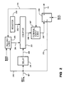
- Figure 1 shows a high level block diagram of a frequency counter using the constant event measurement method and the fast inverse circuit of the invention.
- Figure 2 shows a more detailed block diagram of the constant event counter 105 in Figure 1.
- Figure 3 shows a more detailed schematic block diagram of the inverse circuit 121 in Figure 1.
- Figure 4A illustrates the combination of bits sent to the subtractor 307 if X is in the lower 1/4 of the input range.
- Figure 4B illustrates the combination of bits sent to the subtractor 307 if X is in the upper 3/4 of the input range.
- Figure 5 graphically illustrates the operation of the inverse circuit 121.
- Figure 1 shows a high level block diagram of a frequency counter using the constant event measurement method and the fast inverse circuit of the invention.
- a time counter 101 receives a clock signal on input line 103 from a stable, high frequency clock and produces an output of the accumulated count on line 109.
- An input signal whose frequency is to be measured is applied on line 107 to a constant event counter 105, described in more detail below, that produces an output pulse on line 111 every N input signal events.
- the constant event counter 105 is programmable so that N can be varied.
- the count data on line 109 is applied to the data input of latch 113 and the pulses on line 111 are applied to the enable input of latch 113.
- the current value in the time counter 101 is stored in latch 113.
- the data output of latch 113 on line 115 is a series of time values corresponding to the time of occurrence of sequential blocks of N input signal events.
- the series of time values is applied to a time value processor 117.
- the time value processor produces a series of time interval values on line 119, representing the difference between sets of time values.
- the time values can be processed in a variety of ways, some well known, to produce time interval values. The details of the processing methods are beyond the scope of this invention.
- One simple way to process the time values, that is sufficient to demonstrate the operation of the invention, is to take the difference between successive time values to yield a series of time intervals.
- the time interval values on line 119 are applied to inverse circuit 121, which takes the inverse of the values to produce a series of corresponding frequency values on line 123.
- inverse circuit 121 takes the inverse of the values to produce a series of corresponding frequency values on line 123. The operation of the inverse circuit is explained in more detail below.
- the frequency output values on line 123 can be displayed or stored for postprocessing. Because they are derived from constant event measurements, the time interval signals on line 119 can be applied to triggering circuits with the appropriate time value limits to allow triggering on a desired frequency.
- FIG. 2 shows a more detailed block diagram of the constant event counter 105 in Figure 1.
- Counter 105 is a programmable count down counter that can be reloaded with an initial value when it reaches its terminal count without skipping any cycles. Because it is used to arm for measuring the same signal being counted, it must produce an output in time for a measurement on the immediately following edge. For a 100 MHz input signal, this will occur as soon as 10 ns after the edge initiating the output.
- Counter 201 is an 8 bit down counter. This counter can be implemented in a variety of ways, with one preferred circuit being eight flip flops with the flip flops for the two least significant bits connected in a synchronous configuration and the remaining flip flops connected in a ripple through configuration.
- the counter is asynchronously loaded with an initial state from register 203 via line 202, on the occurrence of a signal from a reload logic circuit 205 on line 204.
- Register 230 can be loaded with the desired preset initial value to provide an output every N input signal events.
- the input signal to be measured, on line 107, is applied to counter 201 on line 206 through a delay 211, described below.
- the output of counter 201 is applied to terminal count logic 207 on line 208.
- a latch output signal of terminal count logic 207 on line 210 is applied to the J input of output latch flip flop 209.
- Flip flop 209 is clocked by the input signal via line 212.
- flip flop 209 produces an output signal on line 111 that is applied to the latch 113 as described above.
- Latch flip flop 209 is reset at the start of each measurement.
- a reload output signal of terminal count logic 207 is applied to reload logic 205 via line 214 to enable reloading when counter 201 reaches its terminal count.
- the input signal is applied to reload logic 205 via line 216.
- Reload logic 205 is reset at the start of each measurement block.
- Delay 211 delays the input signal to the counter 201, to provide time for the counter to recover from the reload. However, this delay also subtracts from the setup time for the output latch flip flop 209. Thus, delay 211 must be long enough to allow the terminal logic and the reload logic, triggered by the undelayed input event edge, to reload the counter 201 before the following delayed input event arrives on line 206. The delay must be short enough so the counter is not reloaded and starting to count when the delayed event edge arrives on line 206. The delay must be short enough so the latch output signal on line 210 reaches the flip flop 209 in time for it to be clocked by following undelayed input event edge on line 212.
- FIG. 3 shows a more detailed schematic block diagram of the inverse circuit 121 in Figure 1.
- the circuit includes a read only memory (ROM) 301, a multiplier 303, a bit field selector multiplexer 305 an a subtractor 307.
- the input to the inverse circuit 121 are the time interval values on line 119. In the embodiment described, these are 16 bit binary words.
- the inverse circuit takes the inverse of the input interval values by approximating a Taylor series expansion.
- Xo can be the more significant bits of X (with the less significant bits assumed to be zero) and (X - Xo) can be the less significant bits. For example, if X is a 16 bit binary number, Xo is the 8 most significant bits and (X -Xo) is the 8 least significant bits. Thus subtraction is not needed to produce the (X - Xo) term used in the expansion.
- the two most significant bits of the input are applied to an or gate 309, and the output is applied to the bit field select multiplexer 305, to control its operation as explained below.
- ROM 301 is a 256 word by 24 bit memory.
- ROM 301 operates as a lookup table with two data outputs, a 16 bit word offset representing the inverse of Xo (1/Xo), and an 8 bit word slope representing 1/Xo 2 .
- the offset is applied to the subtractor 307 on line 302 and the 8 bit slope is applied to multiplier 303 on line 304.
- Multiplier 303 also receives the 8 least significant bits of the input value (representing X - Xo) and multiplies this input by the 8 bit slope (1/Xo 2 ) form the ROM 301, producing a 16 bit output representing the second term of the Taylor series expansion, on line 306.
- the result on line 306 is adjusted by the bit select field as described below, and applied to the subtractor via line 308.
- Subtractor 307 subtracts the second term value on line 308 from the first term offset value on line 302 to produce a final 16 bit output value that represents the inverse (1/X) of the 16 bit time interval input value (X).
- the circuit would have about 8 bit accuracy for a 16 bit input.
- the adjustment function from the actual values improves the accuracy to about 12-13 bits.
- Figure 4A illustrates the combination of bits sent to the subtractor 307 if X is in the lower 1/4 of the input range. This is indicated when the two most significant bits of the input value on line 119 are both 0, and the ORed value on line 312 is thus 0.
- the 4 least significant bits are discarded and the 12 most significant bits are applied to the 12 least significant bits of the subtractor.
- Figure 4B illustrates the combination of bits sent to the subtractor 307 if X is in the upper 3/4 of the input range. This is indicated when either or both of the two most significant bits of the input value on line 119 are 1, and the ORed value on line 312 is thus 1.
- the 8 least significant bits are discarded and the 8 most significant bits are applied to the 8 least significant bits of the subtractor. In this case the multiplier output is shifted down by 4 bits to adjust for the 16 times slope values stored in the ROM table.
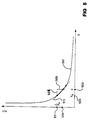
- Figure 5 graphically illustrates the operation of the inverse circuit 121.
- the horizontal axis is the input value X, and the vertical axis is the output value 1/X.
- the curve 501 shows the 1/X relationship.
- Point 503 represents a particular (16 bits) input value X.
- Point 505 represents the Xo (8 bits) applied as the address for ROM 301.
- the hash marks on the horizontal axis illustrate the quantization limit of the 8 bit approximation.
- Point 511 represents the approximation offset value 1/Xo stored (16 bits) in ROM 301, and applied to subtractor 307.
- the length of dashed line segment 507 indicates the difference X - Xo (8 bits), sent to multiplier 303.
- dashed line segment 515 indicates the slope value (1/Xo 2 ) (8 bits) stored in ROM 301 and also sent to multiplier 303.
- the length of dashed line segment 509 indicates the output of multiplier 303, the second Taylor series term (X - Xo)/Xo 2 , as it is applied to subtractor 307.
- point 513 on the vertical axis represents the output (16 bits) of subtractor 307, approximating 1/X.
Landscapes
- Physics & Mathematics (AREA)
- General Physics & Mathematics (AREA)
- Measuring Frequencies, Analyzing Spectra (AREA)
Claims (2)
- Compteur de fréquence pour effectuer des mesures rapides de la fréquence d'un signal d'entrée, comprenant:une source de signaux d'horloge (103);un compteur de temps (101), connecté à la source de signaux d'horloge (103), et comptant les événements des signaux d'horloge pour produire une sortie de comptage de temps (109);un compteur événements constants (105), connecté au signal d'entrée (107), et produisant un signal de sortie d'activation de verrou (111) tous les N événements du signal d'entrée, N étant un entier supérieur à 1;un verrou (113) connecté à la sortie de comptage de temps (109) et à la sortie d'activation de verrou (111), et verrouillant la sortie de comptage de temps (109) à l'apparition de la sortie d'activation de verrou (111), pour produire une sortie de valeur de temps (115) ; etun circuit de calcul de valeur de fréquence (121);caractérisé parun processeur de valeur de temps (117), connecté à la sortie de valeur de temps (115), et produisant une série de signaux de sortie d'intervalle de temps (119), représentant la différence entre des valeurs de temps successives; dans lequelledit circuit de calcul de valeur de fréquence (121) prend l'inverse d'une valeur d'entrée, et est connecté à la sortie d'intervalle de temps (119), et produit une sortie de valeur de fréquence (123) pour chacun des signaux de sortie d'intervalle de temps (119); et dans lequelledit circuit de calcul de valeur de fréquence (121) comprend:une mémoire (301), connectée pour sélectionner les bits les plus significatifs de la sortie d'intervalle de temps (119), et produisant une sortie de décalage (302), représentant le premier terme d'un développement en série de Taylor, et produisant une sortie de pente (304), la sortie de pente (304) étant réglée pour des zones de faible pente;un multiplieur (303), connecté aux bits les moins significatifs sélectionnés de la sortie d'intervalle de temps (119), et à la sortie de pente (304), et produisant une sortie de deuxième terme (306), représentant le deuxième terme d'un développement en série de Taylor;un moyen de sélection de bits (305, 309), connecté à la sortie de deuxième terme (306), et aux bits significatifs sélectionnés de la sortie d'intervalle de temps (119), et sélectionnant les bits supérieurs ou inférieurs de la sortie de deuxième terme (306), en réponse à l'état des bits sélectionnés de la sortie d'intervalle de temps (119), et produisant une sortie de deuxième terme réglée (308);un moyen (307), connecté à la sortie de deuxième terme réglée (308) et à la sortie de décalage (302), et soustrayant la sortie de deuxième terme réglée (308) de la sortie de décalage (302), pour produire la sortie de valeur de fréquence (123).
- Compteur de fréquence selon la revendication 1, dans lequel le compteur événements constants (105) comprend:une logique de rechargement (205), connectée au signal d'entrée (107) et à une logique de comptage final (207), et produisant un signal de rechargement (204);un décompteur rechargeable (201), connecté au signal d'entrée (107) par l'intermédiaire d'un élément de retard (211), et au signal de rechargement (204), et rechargeant le compteur avec une valeur initiale lorsque le compteur (201) atteint un comptage final, pour produire une sortie de comptage (208);une logique de comptage final (207), connectée à la sortie de comptage (208), produisant un signal de sortie de verrou (210), et produisant un signal de sortie de rechargement (214) lorsque le compteur (201) atteint un comptage final; etune logique de sortie (209), connectée au signal d'entrée (107) et au signal de sortie de verrou (210), et produisant une sortie d'activation de verrou (111) sur le front suivant du signal d'entrée (107) qui suit le signal de sortie de verrou (210).
Applications Claiming Priority (2)
| Application Number | Priority Date | Filing Date | Title |
|---|---|---|---|
| US611242 | 1990-11-09 | ||
| US07/611,242 US5128607A (en) | 1990-11-09 | 1990-11-09 | Constant events frequency measurement and fast inverse circuit |
Publications (3)
| Publication Number | Publication Date |
|---|---|
| EP0484629A2 EP0484629A2 (fr) | 1992-05-13 |
| EP0484629A3 EP0484629A3 (en) | 1992-09-09 |
| EP0484629B1 true EP0484629B1 (fr) | 1996-06-12 |
Family
ID=24448230
Family Applications (1)
| Application Number | Title | Priority Date | Filing Date |
|---|---|---|---|
| EP91110690A Expired - Lifetime EP0484629B1 (fr) | 1990-11-09 | 1991-06-27 | Mesure de fréquence basée sur un nombre constant d'événements avec un circuit inverse rapide |
Country Status (5)
| Country | Link |
|---|---|
| US (1) | US5128607A (fr) |
| EP (1) | EP0484629B1 (fr) |
| JP (1) | JP3214717B2 (fr) |
| DE (1) | DE69120207T2 (fr) |
| HK (1) | HK210596A (fr) |
Families Citing this family (17)
| Publication number | Priority date | Publication date | Assignee | Title |
|---|---|---|---|---|
| US6263290B1 (en) | 1995-02-22 | 2001-07-17 | Michael K. Williams | Process and machine for signal waveform analysis |
| JP3434095B2 (ja) * | 1995-09-08 | 2003-08-04 | 株式会社アドバンテスト | 周波数測定装置 |
| US5883818A (en) * | 1996-08-29 | 1999-03-16 | International Business Machines Corporation | Method for generating an improved model for evaluating the operation of an integrated circuit design |
| DE19724742C2 (de) * | 1997-06-12 | 1999-03-25 | Georg Dieter Dr Mirow | Verfahren und Vorrichtung zur Anzeige von statistisch auftretenden Ereignissen |
| US6502201B1 (en) * | 1999-10-14 | 2002-12-31 | International Business Machines Corporation | Determination of frequency of timer ticks |
| US7798456B2 (en) * | 2007-08-21 | 2010-09-21 | Hill-Rom Services, Inc. | Transferable patient care equipment support |
| WO2009026435A1 (fr) * | 2007-08-23 | 2009-02-26 | Amherst Systems Associates, Inc. | Systèmes et procédés de détection et de notification d'anomalies de formes d'onde |
| JP2009250807A (ja) * | 2008-04-07 | 2009-10-29 | Seiko Epson Corp | 周波数測定装置及び測定方法 |
| US8422340B2 (en) * | 2008-12-08 | 2013-04-16 | General Electric Company | Methods for determining the frequency or period of a signal |
| JP2010271091A (ja) | 2009-05-20 | 2010-12-02 | Seiko Epson Corp | 周波数測定装置 |
| JP5440999B2 (ja) | 2009-05-22 | 2014-03-12 | セイコーエプソン株式会社 | 周波数測定装置 |
| JP5517033B2 (ja) | 2009-05-22 | 2014-06-11 | セイコーエプソン株式会社 | 周波数測定装置 |
| JP5582447B2 (ja) * | 2009-08-27 | 2014-09-03 | セイコーエプソン株式会社 | 電気回路、同電気回路を備えたセンサーシステム、及び同電気回路を備えたセンサーデバイス |
| JP5815918B2 (ja) | 2009-10-06 | 2015-11-17 | セイコーエプソン株式会社 | 周波数測定方法、周波数測定装置及び周波数測定装置を備えた装置 |
| JP5876975B2 (ja) | 2009-10-08 | 2016-03-02 | セイコーエプソン株式会社 | 周波数測定装置及び周波数測定装置における変速分周信号の生成方法 |
| JP5883558B2 (ja) | 2010-08-31 | 2016-03-15 | セイコーエプソン株式会社 | 周波数測定装置及び電子機器 |
| US9030188B2 (en) | 2012-03-14 | 2015-05-12 | Rockwell Automation Technologies, Inc. | Wide range, high resolution frequency monitor |
Family Cites Families (10)
| Publication number | Priority date | Publication date | Assignee | Title |
|---|---|---|---|---|
| JPS567592B2 (fr) * | 1974-10-31 | 1981-02-18 | ||
| US4093850A (en) * | 1977-02-22 | 1978-06-06 | Cutler-Hammer, Inc. | Ratemeter which calculates the reciprocal of the period |
| US4257005A (en) * | 1979-05-23 | 1981-03-17 | Hall David S | Fixed interval variable period pulse rate measuring method and system and tachometer system using same |
| DE2921899A1 (de) * | 1979-05-30 | 1980-12-04 | Nord Micro Elektronik Feinmech | Verfahren zur frequenzmessung |
| JPS5948660A (ja) * | 1982-09-13 | 1984-03-19 | Advantest Corp | 周波数及び周期測定装置 |
| JPS6097183A (ja) * | 1983-10-28 | 1985-05-30 | 三菱電機株式会社 | エレベ−タの速度検出装置 |
| JPS61137077A (ja) * | 1984-12-07 | 1986-06-24 | Sankyo Denshi Kk | 周波数判別器 |
| US4707653A (en) * | 1985-10-17 | 1987-11-17 | Ampex Corporation | Frequency measurement circuit |
| JPS63118936A (ja) * | 1986-11-07 | 1988-05-23 | Matsushita Electric Ind Co Ltd | 倍精度演算装置 |
| US4786861A (en) * | 1987-09-01 | 1988-11-22 | Sundstrand Data Control, Inc. | Frequency counting apparatus and method |
-
1990
- 1990-11-09 US US07/611,242 patent/US5128607A/en not_active Expired - Lifetime
-
1991
- 1991-06-27 DE DE69120207T patent/DE69120207T2/de not_active Expired - Fee Related
- 1991-06-27 EP EP91110690A patent/EP0484629B1/fr not_active Expired - Lifetime
- 1991-11-08 JP JP32093491A patent/JP3214717B2/ja not_active Expired - Fee Related
-
1996
- 1996-11-28 HK HK210596A patent/HK210596A/xx not_active IP Right Cessation
Non-Patent Citations (1)
| Title |
|---|
| U. Tietze, Ch. Schenk: "Halbleiter-Schaltungstechnik", 8th edition, 1986, Springer-Verlag, Berlin ..., pages 250-251 * |
Also Published As
| Publication number | Publication date |
|---|---|
| JPH06342021A (ja) | 1994-12-13 |
| EP0484629A3 (en) | 1992-09-09 |
| EP0484629A2 (fr) | 1992-05-13 |
| JP3214717B2 (ja) | 2001-10-02 |
| DE69120207T2 (de) | 1997-01-16 |
| US5128607A (en) | 1992-07-07 |
| HK210596A (en) | 1996-12-06 |
| DE69120207D1 (de) | 1996-07-18 |
Similar Documents
| Publication | Publication Date | Title |
|---|---|---|
| EP0484629B1 (fr) | Mesure de fréquence basée sur un nombre constant d'événements avec un circuit inverse rapide | |
| US4975636A (en) | Method and apparatus for selecting and displaying a high resolution window from a main display | |
| EP2301145B1 (fr) | Circuit avec un convertisseur numérique de temps et procédé de mesure de phase | |
| US4485452A (en) | Speed measurement system | |
| US5367200A (en) | Method and apparatus for measuring the duty cycle of a digital signal | |
| US6271773B1 (en) | Coherent sampling method and apparatus | |
| US5557196A (en) | Jitter analyzer | |
| US4809221A (en) | Timing signal generator | |
| US5959479A (en) | Sampling timebase system | |
| US7280930B2 (en) | Sequential timebase | |
| Johansson | New frequency counting principle improves resolution | |
| US4637733A (en) | High-resolution electronic chronometry system | |
| Baron | The vernier time-measuring technique | |
| US4982196A (en) | Radar target simulator | |
| US4773031A (en) | Method and circuit for digital frequency multiplication | |
| US3764903A (en) | Phase measuring system | |
| US6522983B1 (en) | Timebase calibration method for an equivalent time sampling digitizing instrument | |
| Chaberski et al. | Comparison of interpolators used for time-interval measurement systems based on multiple-tapped delay line | |
| GB2234825A (en) | Digital gate generation for signal measurement apparatus | |
| US4779221A (en) | Timing signal generator | |
| US6377644B1 (en) | Periodic signal digital testing | |
| US4251777A (en) | Method of and apparatus for time-stabilization of sampling pulses | |
| US4383166A (en) | Automatic echo-chamber for measuring single time intervals by replication and averaging | |
| JPH0783980A (ja) | ジッタ/ワンダ解析装置 | |
| US4392749A (en) | Instrument for determining coincidence and elapse time between independent sources of random sequential events |
Legal Events
| Date | Code | Title | Description |
|---|---|---|---|
| PUAI | Public reference made under article 153(3) epc to a published international application that has entered the european phase |
Free format text: ORIGINAL CODE: 0009012 |
|
| AK | Designated contracting states |
Kind code of ref document: A2 Designated state(s): DE FR GB |
|
| PUAL | Search report despatched |
Free format text: ORIGINAL CODE: 0009013 |
|
| AK | Designated contracting states |
Kind code of ref document: A3 Designated state(s): DE FR GB |
|
| 17P | Request for examination filed |
Effective date: 19930215 |
|
| 17Q | First examination report despatched |
Effective date: 19941103 |
|
| GRAH | Despatch of communication of intention to grant a patent |
Free format text: ORIGINAL CODE: EPIDOS IGRA |
|
| GRAA | (expected) grant |
Free format text: ORIGINAL CODE: 0009210 |
|
| AK | Designated contracting states |
Kind code of ref document: B1 Designated state(s): DE FR GB |
|
| REF | Corresponds to: |
Ref document number: 69120207 Country of ref document: DE Date of ref document: 19960718 |
|
| ET | Fr: translation filed | ||
| PLBE | No opposition filed within time limit |
Free format text: ORIGINAL CODE: 0009261 |
|
| STAA | Information on the status of an ep patent application or granted ep patent |
Free format text: STATUS: NO OPPOSITION FILED WITHIN TIME LIMIT |
|
| 26N | No opposition filed | ||
| PGFP | Annual fee paid to national office [announced via postgrant information from national office to epo] |
Ref country code: FR Payment date: 19980520 Year of fee payment: 8 |
|
| PGFP | Annual fee paid to national office [announced via postgrant information from national office to epo] |
Ref country code: GB Payment date: 19980526 Year of fee payment: 8 |
|
| PGFP | Annual fee paid to national office [announced via postgrant information from national office to epo] |
Ref country code: DE Payment date: 19980527 Year of fee payment: 8 |
|
| PG25 | Lapsed in a contracting state [announced via postgrant information from national office to epo] |
Ref country code: GB Free format text: LAPSE BECAUSE OF NON-PAYMENT OF DUE FEES Effective date: 19990627 |
|
| PG25 | Lapsed in a contracting state [announced via postgrant information from national office to epo] |
Ref country code: FR Free format text: THE PATENT HAS BEEN ANNULLED BY A DECISION OF A NATIONAL AUTHORITY Effective date: 19990630 |
|
| GBPC | Gb: european patent ceased through non-payment of renewal fee |
Effective date: 19990627 |
|
| PG25 | Lapsed in a contracting state [announced via postgrant information from national office to epo] |
Ref country code: DE Free format text: LAPSE BECAUSE OF NON-PAYMENT OF DUE FEES Effective date: 20000503 |
|
| REG | Reference to a national code |
Ref country code: FR Ref legal event code: ST |