EP0483310B1 - Anti tip-off ejection seat rails - Google Patents
Anti tip-off ejection seat rails Download PDFInfo
- Publication number
- EP0483310B1 EP0483310B1 EP91908097A EP91908097A EP0483310B1 EP 0483310 B1 EP0483310 B1 EP 0483310B1 EP 91908097 A EP91908097 A EP 91908097A EP 91908097 A EP91908097 A EP 91908097A EP 0483310 B1 EP0483310 B1 EP 0483310B1
- Authority
- EP
- European Patent Office
- Prior art keywords
- guide
- rail
- channel
- guides
- seat
- Prior art date
- Legal status (The legal status is an assumption and is not a legal conclusion. Google has not performed a legal analysis and makes no representation as to the accuracy of the status listed.)
- Expired - Lifetime
Links
Images
Classifications
-
- B—PERFORMING OPERATIONS; TRANSPORTING
- B64—AIRCRAFT; AVIATION; COSMONAUTICS
- B64D—EQUIPMENT FOR FITTING IN OR TO AIRCRAFT; FLIGHT SUITS; PARACHUTES; ARRANGEMENT OR MOUNTING OF POWER PLANTS OR PROPULSION TRANSMISSIONS IN AIRCRAFT
- B64D25/00—Emergency apparatus or devices, not otherwise provided for
- B64D25/08—Ejecting or escaping means
- B64D25/10—Ejector seats
Definitions
- the seat will have two or three rollers on each side, wherein each set of rollers travels along a single channel in the corresponding rail.
- Each side of the seat usually has a toilet at the bottom, one in the middle and one near the top.
- the seat reaches a point where the top and middle rollers have disengaged from the rail but the bottom rollers are still constrained by the rails.
- the wind blast will push the top of the seat aft of the vehicle while the rail constrains the bottom of the vehicle, producing a rotational moment on the seat and causing an undesirable aft pitch angle.
- the James patent discloses tour pairs of guides 80, 81, 82, and 83.
- Figures 16 through 19 in the James patent illustrate three different shapes for the guides: one shape is illustrated in Figure 17 for guide pair 80; the second shape is illustrated in Figure 18 for guide pairs 81 and 82; and the third shape is illustrated in Figure 19 for guide pair 83.
- the James patent discloses that, during ejection, the guide pairs 80, 81, 82, and 83 disengage from the two rails sequentially, with pair 80 disengaging first, pair 81 disengaging second, pair 82 disengaging third, and pair 83 disengaging last (see Figures 20 through 22 in the James patent).
- the present invention may be described as a structure that guides an ejection seat out of a vehicle, the structure comprising one first guide, one second guide, and at least one rail, the structure being characterized in that: said first guide is attachable to said ejection seat at a predetermined point, said second guide is attachable to said ejection seat at a point which is lower than said predetermined point by a predetermined distance, said second guide is separated from said first guide, said rail is attachable to said vehicle, said rail has a first channel and a second channel, said first guide resides within said first channel and said second guide resides within said second channel when the guides are attached to the ejection seat and the rail to the vehicle and the ejection seat is positioned in the vehicle, said first and second guides are adapted to travel along said first and second channels respectively and to exit from said channels at the ends of said channels, the end of said first channel being at a distance from the end of said second channel approximately equal to said predetermined distance, such that when said ejection seat travels along said rail said first and
- the present invention may be described as a structure that guides an ejection seat out of a vehicle, the structure comprising at least one first guide, at least one second guide, and at least one rail, the structure being characterized in that: said first guide is attachable to said ejection seat at a predetermined point, said second guide is attachable to said ejection seat at a point which is lower than said predetermined point by a predetermined distance, said rail is attachable to the vehicle and forms a stepped "C" channel having a base and a pair of flanges, said flanges have a portion nearer the base forming a first channel and a portion further from the base forming a second channel, said second channel is wider than said first channel, said first guide resides within said first channel and said second guide resides within said second channel when the guides are attached to the ejection seat and the rail to the vehicle and the ejection seat is positioned in the vehicle, said first and second guides are adapted to travel along said first and second channels respectively and to exit from said channels
- the present invention may be further described as a structure that guides an ejection seat out of a vehicle, the structure comprising at least one first guide, at least one second guide, and at least one rail, the structure being characterized in that: said first guide is attachable to said ejection seat; said rail is attachable to said vehicle; said rail has a single channel; at least one lever is pivotally connectable to said ejection seat; said second guide is connected to said lever; said second guide is located in close proximity to said first guide; at least one third guide is pivotally connected to said lever; said first, said second, and said third guides reside within said single channel when the first guide and the lever are connected to the ejection seat and the rail to the vehicle and the ejection seat is positioned in the vehicle; said first, said second, and said third guides are adapted to travel along and exit said single channel; said first guide exits said single channel before said second and third guides; said second guide exits said single channel before said third guide; said lever is of such width and attachable to said ejection seat at
- the present invention may be further described as a structure that guides an ejection seat out of a vehicle, the structure comprising at least one first guide, at least one second guide, and at least one rail, the structure being characterized in that: said first and second guides are attachable to said ejection seat, said rail is attachable to said vehicle, said rail has a single channel, said rail has a longitudinal axis, said first and second guides reside in said single channel when the guides are attached to the ejection seat and the rail to the vehicle and the ejection seat is positioned in the vehicle and are adapted to travel along said single channel and exit from the end of said single channel, said rail has a curvature along said longitudinal axis such that said rail will tend to bend to direct the seat out of the vehicle at a desirable pitch angle if a force is exerted on said seat during ejection.
- the rails according to the first three aspects of the invention described above may also have a curvature so that when the beam bends during seat ejection, the beam will bend toward a more linear position, reducing or eliminating the amount of aft pitch caused by rail deflection.
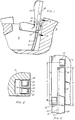
- Figure 1 shows an ejection seat 2 traveling up a rail 4 which is mounted into the cockpit 6 of an aircraft 8.
- the ejection seat 2 can be any standard seat used in the aircraft industry such as the rocket catapult seat sold by McDonnell Douglas under the trademark ACES II. Attached to the side of the seat 2 are first 10 and second 12 guides that ride along and are constrained by first 14 and second 16 channels in the rail 4, respectively. To provide further stability a top guide 18 can be attached to the seat 2, the top guide 18 travels along the first channel 14. Another set of guides, channels and rail can be placed on the other side of the seat 2 and if desirable could also be located in the center of the seat 2.
- the guides should preferably be rollers, but any conventional guide means that can travel along the channels can be used.
- the rail 4 can be constructed from a I-beam, wherein a first 20 set of flanges form the first channel 14 and a second 22 set of flanges form the second channel 16.
- the second flange set 22 is cut, such that the second channel 16 terminates at a distance x from the end of the first channel 14, the distance x approximately equaling the distance between the first guide 10 and the second guide 12, see Figure 3.
- FIGs 4, 5 and 6 show an alternative embodiment to the structure depicted in Figures 1-3.
- a stepped "C" channel is used.
- the C channel rail 24 has a set of flanges 26 that differ in width as they extend from the base 28 of the rail 24.
- the C rail 24 is constructed such that the flanges 26 are thicker near the base 28 of the rail 24.
- the lover part 30 of the flanges form a first channel 14' and the upper part 32 of the flanges form a second channel 16'.
- a first guide 10' or roller is attached to the seat 2 by a first pin 34. The first guide 10' travels along the first channel 14'.
- a second guide 12' is attached to the seat 2 by a second pin 36 and travels along the second channel 16'.
- the second channel 16' terminates at a distance X from the end of the first channel 14', approximately equal to the distance between the bottom of the first guide 10' and the bottom of the second guide 12', such that the guides exit the channels simultaneously, see Figure 6.
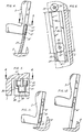
- the rail 37 has one single channel 38.
- a first guide 10'' is attached to the seat 2 and travels along the single channel 38.
- a lever 40 is pivotally mounted to the seat 2 by attachment means such as a third pin 42.
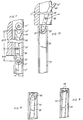
- Extending from or attached to the lever 40 is a second guide 12'', which could be a pair of guide flanges 44 as depicted in Figure 7, or a roller 46 as shown in Figure 8, or a pair of rollers 48 as shown in Figure 9.
- a third guide 50 is pivotally attached to the lever 40 by attachment means such as a fourth pin 52. Both the second 12'' and third 50 guides travel along the single channel 38.
- the second guide 12'' is in close proximity to the first guide 10'', so that the first 10'' and second 12'' guides exit the single channel 38 at approximately the same time.
- the lever 40 and the attached seat 2 are allowed to move in the direction as indicated in Figure 10. Because the seat is attached to the lever 40 and the lever 40 is allowed to rotate about the third guide 50, the seat 2 is allowed to move freely without being restrained by the third guide 50.
- the second 12'' and third 50 guides functionally release simultaneously, similar to the releasing mechanism shown in Figures 1-6. To prevent the seat 4 from being restrained between the time the second 12'' and third 50 guides release, it is desirable to prevent contact between the lever 40 and the rail 37.
- the geometric relationship between the lever 40, second guide 12'', third guide 50 and channel 38 must be established to prevent the lever 40 from making contact with the rail 37, when the seat 2 is subjected to a predetermined windblast.
- a predetermined windblast 700 knots equivalent air speed (KEAS)
- KEAS 700 knots equivalent air speed
- the width of the channel 38 is 4.445 cm.
- the lever 40 will avoid channel contact, by using a lever no wider than 2.2 cm, and placing the third pin 42 approximately .95 cm from the center of the channel 38 at a distance of 20.32 cm from the edge of the second guide 12'' and 3.49 cm from the center of the third guide 50.
- the windblast exerts a load on the seat 2, which is transmitted to the rail 4, causing the rail 4 to deflect.
- the rail 4' can be curved toward the fore position as shown in Figure 11.
- the rail 4' will bend toward a linear position, which allows the seat 2 to exit from the cockpit 6 without rotational velocity, see Figure 12. It has been calculated that for a maximum windblast of 700 KEAS, the rail 4 should have a radius of approximately 5° degrees.
- the curved rail concept can be used with or without any of the three simultaneous guide release mechanisms previously disclosed.
Landscapes
- Business, Economics & Management (AREA)
- Emergency Management (AREA)
- Engineering & Computer Science (AREA)
- Aviation & Aerospace Engineering (AREA)
- Seats For Vehicles (AREA)
- Discharge By Other Means (AREA)
- Lock And Its Accessories (AREA)
- Fuel-Injection Apparatus (AREA)
- Transplanting Machines (AREA)
- Absorbent Articles And Supports Therefor (AREA)
- Soil Working Implements (AREA)
- Catching Or Destruction (AREA)
- Details Or Accessories Of Spraying Plant Or Apparatus (AREA)
Applications Claiming Priority (3)
| Application Number | Priority Date | Filing Date | Title |
|---|---|---|---|
| US498394 | 1990-02-26 | ||
| US07/498,394 US5067671A (en) | 1990-02-26 | 1990-02-26 | Anti tip-off ejection rails |
| PCT/US1991/001241 WO1991012989A1 (en) | 1990-02-26 | 1991-02-25 | Anti tip-off ejection rails |
Publications (3)
| Publication Number | Publication Date |
|---|---|
| EP0483310A1 EP0483310A1 (en) | 1992-05-06 |
| EP0483310A4 EP0483310A4 (en) | 1993-06-02 |
| EP0483310B1 true EP0483310B1 (en) | 1997-04-23 |
Family
ID=23980912
Family Applications (1)
| Application Number | Title | Priority Date | Filing Date |
|---|---|---|---|
| EP91908097A Expired - Lifetime EP0483310B1 (en) | 1990-02-26 | 1991-02-25 | Anti tip-off ejection seat rails |
Country Status (9)
| Country | Link |
|---|---|
| US (1) | US5067671A (da) |
| EP (1) | EP0483310B1 (da) |
| JP (1) | JP2933717B2 (da) |
| AT (1) | ATE152064T1 (da) |
| DE (1) | DE69125784T2 (da) |
| DK (1) | DK0483310T3 (da) |
| ES (1) | ES2100228T3 (da) |
| GR (1) | GR3024206T3 (da) |
| WO (1) | WO1991012989A1 (da) |
Cited By (1)
| Publication number | Priority date | Publication date | Assignee | Title |
|---|---|---|---|---|
| KR101567823B1 (ko) | 2014-05-14 | 2015-11-10 | 임종민 | 비행기 겸용 자동차의 슬라이드 사출시트 및 그 구동방법 |
Families Citing this family (6)
| Publication number | Priority date | Publication date | Assignee | Title |
|---|---|---|---|---|
| GB9906987D0 (en) * | 1999-03-25 | 1999-05-19 | Baker Martin Aircraft Co | An ejection seat |
| US6315245B1 (en) * | 2000-03-14 | 2001-11-13 | Martin-Baker Aircraft Company, Limited | Ejection seat with blast protection system |
| WO2018190744A1 (ru) * | 2017-04-10 | 2018-10-18 | Евгений Станиславович ФОКИН | Устройство для спасения экипажа и пассажиров летательных аппаратов |
| US11427338B2 (en) * | 2018-11-16 | 2022-08-30 | Ami Industries, Inc. | Inclining curved ejection seat assemblies |
| US11613367B2 (en) * | 2021-06-02 | 2023-03-28 | Ami Industries, Inc. | Ejection seat and rail assemblies for aircraft evacuation systems |
| CN116811693A (zh) * | 2023-06-06 | 2023-09-29 | 奇瑞汽车股份有限公司 | 用于飞行汽车的弹射座椅及具有其的车辆 |
Family Cites Families (10)
| Publication number | Priority date | Publication date | Assignee | Title |
|---|---|---|---|---|
| US2569638A (en) * | 1949-11-28 | 1951-10-02 | Martin James | Control means for use with ejection seats of aircraft |
| US2638293A (en) * | 1951-02-10 | 1953-05-12 | United Aircraft Corp | Restraining and releasing device for pilots |
| US2755042A (en) * | 1954-12-10 | 1956-07-17 | Henry A Paddon | Ejection seat catapult |
| US2879715A (en) * | 1956-09-25 | 1959-03-31 | Svenska Aeroplan Ab | Ejection seat for airplanes |
| US2829850A (en) * | 1956-11-13 | 1958-04-08 | Lockheed Aircraft Corp | Aircraft ejection seat |
| US3130947A (en) * | 1960-11-30 | 1964-04-28 | Franks Charles Glen | Ejection seat catapult |
| US3214117A (en) | 1964-01-07 | 1965-10-26 | Weber Aircraft Corp | Ejection seat arrangement |
| US3442473A (en) * | 1965-10-23 | 1969-05-06 | Stanley Aviation Corp | Catapult-assisted tractor rocket escape system |
| US3421720A (en) * | 1966-05-27 | 1969-01-14 | Us Army | Aircraft seat ejection system |
| US3647168A (en) | 1970-04-27 | 1972-03-07 | Budd Co | Ejection seat arrangement |
-
1990
- 1990-02-26 US US07/498,394 patent/US5067671A/en not_active Expired - Fee Related
-
1991
- 1991-02-25 ES ES91908097T patent/ES2100228T3/es not_active Expired - Lifetime
- 1991-02-25 DE DE69125784T patent/DE69125784T2/de not_active Expired - Fee Related
- 1991-02-25 DK DK91908097.8T patent/DK0483310T3/da active
- 1991-02-25 AT AT91908097T patent/ATE152064T1/de not_active IP Right Cessation
- 1991-02-25 JP JP3507575A patent/JP2933717B2/ja not_active Expired - Lifetime
- 1991-02-25 WO PCT/US1991/001241 patent/WO1991012989A1/en not_active Ceased
- 1991-02-25 EP EP91908097A patent/EP0483310B1/en not_active Expired - Lifetime
-
1997
- 1997-07-23 GR GR970401852T patent/GR3024206T3/el unknown
Cited By (1)
| Publication number | Priority date | Publication date | Assignee | Title |
|---|---|---|---|---|
| KR101567823B1 (ko) | 2014-05-14 | 2015-11-10 | 임종민 | 비행기 겸용 자동차의 슬라이드 사출시트 및 그 구동방법 |
Also Published As
| Publication number | Publication date |
|---|---|
| US5067671A (en) | 1991-11-26 |
| ATE152064T1 (de) | 1997-05-15 |
| GR3024206T3 (en) | 1997-10-31 |
| DE69125784T2 (de) | 1997-11-27 |
| EP0483310A1 (en) | 1992-05-06 |
| DK0483310T3 (da) | 1997-10-27 |
| JP2933717B2 (ja) | 1999-08-16 |
| EP0483310A4 (en) | 1993-06-02 |
| ES2100228T3 (es) | 1997-06-16 |
| DE69125784D1 (de) | 1997-05-28 |
| WO1991012989A1 (en) | 1991-09-05 |
| JPH05502203A (ja) | 1993-04-22 |
Similar Documents
| Publication | Publication Date | Title |
|---|---|---|
| AU679365B2 (en) | Safety brake apparatus for an elevator car or counterweight | |
| US5100081A (en) | Aircraft control system | |
| US4550663A (en) | Transportation system having a cable drawn vehicle | |
| US5067671A (en) | Anti tip-off ejection rails | |
| GB2150895A (en) | Load deployment device | |
| US4836298A (en) | Boat of the catamaran type, propelled mechanically | |
| US4949815A (en) | Sheave array of a self propelled elevator using a linear motor on the counterweight | |
| JPH081314U (ja) | 車両の安全ベルトシステム用のベルト・プリテンショナー | |
| EP0091921A1 (en) | A system for load handling | |
| JPH026237A (ja) | 車両座席用安全スライド | |
| US4451060A (en) | Device for vehicle safety belts | |
| US6622637B2 (en) | Arcuate tilting mechanism for high speed trains | |
| JP2002532212A (ja) | 娯楽装置 | |
| US4209148A (en) | Flying wing | |
| US3931769A (en) | Automatic opening and closing cabin for ropeways | |
| US3545757A (en) | Racing toy having vehicle propelling and arresting means | |
| DE69015935T2 (de) | Schienenfahrzeug und dazugehörige Schienenanlage. | |
| US2446609A (en) | Releasable airplane cabin | |
| US1800746A (en) | Means for controlling aeroplanes | |
| US4398640A (en) | Multi-span skyline logging system | |
| US5520261A (en) | Static trimmer for a hovercraft | |
| US4386517A (en) | Pulling tower structure | |
| US5573205A (en) | Pull cord tension transmitting device using dual rack-pinion | |
| GB1590156A (en) | Curved guide for paternostertype document carriers | |
| JPH02291307A (ja) | 連続輸送システム用の連続チェーン |
Legal Events
| Date | Code | Title | Description |
|---|---|---|---|
| PUAI | Public reference made under article 153(3) epc to a published international application that has entered the european phase |
Free format text: ORIGINAL CODE: 0009012 |
|
| 17P | Request for examination filed |
Effective date: 19920224 |
|
| AK | Designated contracting states |
Kind code of ref document: A1 Designated state(s): AT BE CH DE DK ES FR GB GR IT LI LU NL SE |
|
| A4 | Supplementary search report drawn up and despatched |
Effective date: 19930416 |
|
| AK | Designated contracting states |
Kind code of ref document: A4 Designated state(s): AT BE CH DE DK ES FR GB GR IT LI LU NL SE |
|
| 17Q | First examination report despatched |
Effective date: 19940704 |
|
| GRAG | Despatch of communication of intention to grant |
Free format text: ORIGINAL CODE: EPIDOS AGRA |
|
| GRAH | Despatch of communication of intention to grant a patent |
Free format text: ORIGINAL CODE: EPIDOS IGRA |
|
| GRAH | Despatch of communication of intention to grant a patent |
Free format text: ORIGINAL CODE: EPIDOS IGRA |
|
| GRAA | (expected) grant |
Free format text: ORIGINAL CODE: 0009210 |
|
| AK | Designated contracting states |
Kind code of ref document: B1 Designated state(s): AT BE CH DE DK ES FR GB GR IT LI LU NL SE |
|
| REF | Corresponds to: |
Ref document number: 152064 Country of ref document: AT Date of ref document: 19970515 Kind code of ref document: T |
|
| REG | Reference to a national code |
Ref country code: CH Ref legal event code: EP |
|
| REF | Corresponds to: |
Ref document number: 69125784 Country of ref document: DE Date of ref document: 19970528 |
|
| REG | Reference to a national code |
Ref country code: CH Ref legal event code: NV Representative=s name: PATENTANWALTSBUREAU R. A. MASPOLI |
|
| REG | Reference to a national code |
Ref country code: ES Ref legal event code: FG2A Ref document number: 2100228 Country of ref document: ES Kind code of ref document: T3 |
|
| ET | Fr: translation filed | ||
| REG | Reference to a national code |
Ref country code: GR Ref legal event code: FG4A Free format text: 3024206 |
|
| REG | Reference to a national code |
Ref country code: DK Ref legal event code: T3 |
|
| PGFP | Annual fee paid to national office [announced via postgrant information from national office to epo] |
Ref country code: DK Payment date: 19980127 Year of fee payment: 8 |
|
| PGFP | Annual fee paid to national office [announced via postgrant information from national office to epo] |
Ref country code: SE Payment date: 19980128 Year of fee payment: 8 Ref country code: LU Payment date: 19980128 Year of fee payment: 8 |
|
| PGFP | Annual fee paid to national office [announced via postgrant information from national office to epo] |
Ref country code: NL Payment date: 19980130 Year of fee payment: 8 Ref country code: GR Payment date: 19980130 Year of fee payment: 8 |
|
| PGFP | Annual fee paid to national office [announced via postgrant information from national office to epo] |
Ref country code: AT Payment date: 19980203 Year of fee payment: 8 |
|
| PGFP | Annual fee paid to national office [announced via postgrant information from national office to epo] |
Ref country code: CH Payment date: 19980204 Year of fee payment: 8 |
|
| PGFP | Annual fee paid to national office [announced via postgrant information from national office to epo] |
Ref country code: BE Payment date: 19980217 Year of fee payment: 8 |
|
| PGFP | Annual fee paid to national office [announced via postgrant information from national office to epo] |
Ref country code: ES Payment date: 19980223 Year of fee payment: 8 |
|
| PLBE | No opposition filed within time limit |
Free format text: ORIGINAL CODE: 0009261 |
|
| STAA | Information on the status of an ep patent application or granted ep patent |
Free format text: STATUS: NO OPPOSITION FILED WITHIN TIME LIMIT |
|
| 26N | No opposition filed | ||
| PGFP | Annual fee paid to national office [announced via postgrant information from national office to epo] |
Ref country code: GB Payment date: 19990203 Year of fee payment: 9 Ref country code: FR Payment date: 19990203 Year of fee payment: 9 |
|
| PGFP | Annual fee paid to national office [announced via postgrant information from national office to epo] |
Ref country code: DE Payment date: 19990204 Year of fee payment: 9 |
|
| PG25 | Lapsed in a contracting state [announced via postgrant information from national office to epo] |
Ref country code: LU Free format text: LAPSE BECAUSE OF NON-PAYMENT OF DUE FEES Effective date: 19990225 Ref country code: AT Free format text: LAPSE BECAUSE OF NON-PAYMENT OF DUE FEES Effective date: 19990225 |
|
| PG25 | Lapsed in a contracting state [announced via postgrant information from national office to epo] |
Ref country code: SE Free format text: LAPSE BECAUSE OF NON-PAYMENT OF DUE FEES Effective date: 19990226 Ref country code: ES Free format text: LAPSE BECAUSE OF NON-PAYMENT OF DUE FEES Effective date: 19990226 |
|
| PG25 | Lapsed in a contracting state [announced via postgrant information from national office to epo] |
Ref country code: LI Free format text: LAPSE BECAUSE OF NON-PAYMENT OF DUE FEES Effective date: 19990228 Ref country code: GR Free format text: LAPSE BECAUSE OF NON-PAYMENT OF DUE FEES Effective date: 19990228 Ref country code: CH Free format text: LAPSE BECAUSE OF NON-PAYMENT OF DUE FEES Effective date: 19990228 Ref country code: BE Free format text: LAPSE BECAUSE OF NON-PAYMENT OF DUE FEES Effective date: 19990228 |
|
| PG25 | Lapsed in a contracting state [announced via postgrant information from national office to epo] |
Ref country code: DK Free format text: LAPSE BECAUSE OF NON-PAYMENT OF DUE FEES Effective date: 19990301 |
|
| BERE | Be: lapsed |
Owner name: MCDONNELL DOUGLAS CORP. Effective date: 19990228 |
|
| PG25 | Lapsed in a contracting state [announced via postgrant information from national office to epo] |
Ref country code: NL Free format text: LAPSE BECAUSE OF NON-PAYMENT OF DUE FEES Effective date: 19990901 |
|
| REG | Reference to a national code |
Ref country code: CH Ref legal event code: PL |
|
| EUG | Se: european patent has lapsed |
Ref document number: 91908097.8 |
|
| REG | Reference to a national code |
Ref country code: DK Ref legal event code: EBP |
|
| PG25 | Lapsed in a contracting state [announced via postgrant information from national office to epo] |
Ref country code: GB Free format text: LAPSE BECAUSE OF NON-PAYMENT OF DUE FEES Effective date: 20000225 |
|
| GBPC | Gb: european patent ceased through non-payment of renewal fee |
Effective date: 20000225 |
|
| PG25 | Lapsed in a contracting state [announced via postgrant information from national office to epo] |
Ref country code: FR Free format text: LAPSE BECAUSE OF NON-PAYMENT OF DUE FEES Effective date: 20001031 |
|
| PG25 | Lapsed in a contracting state [announced via postgrant information from national office to epo] |
Ref country code: DE Free format text: LAPSE BECAUSE OF NON-PAYMENT OF DUE FEES Effective date: 20001201 |
|
| REG | Reference to a national code |
Ref country code: FR Ref legal event code: ST |
|
| REG | Reference to a national code |
Ref country code: ES Ref legal event code: FD2A Effective date: 20010910 |
|
| PG25 | Lapsed in a contracting state [announced via postgrant information from national office to epo] |
Ref country code: IT Free format text: LAPSE BECAUSE OF NON-PAYMENT OF DUE FEES;WARNING: LAPSES OF ITALIAN PATENTS WITH EFFECTIVE DATE BEFORE 2007 MAY HAVE OCCURRED AT ANY TIME BEFORE 2007. THE CORRECT EFFECTIVE DATE MAY BE DIFFERENT FROM THE ONE RECORDED. Effective date: 20050225 |