EP0483225B1 - Handgehaltene mehrkanälige pipettierungsvorrichtung - Google Patents
Handgehaltene mehrkanälige pipettierungsvorrichtung Download PDFInfo
- Publication number
- EP0483225B1 EP0483225B1 EP90911212A EP90911212A EP0483225B1 EP 0483225 B1 EP0483225 B1 EP 0483225B1 EP 90911212 A EP90911212 A EP 90911212A EP 90911212 A EP90911212 A EP 90911212A EP 0483225 B1 EP0483225 B1 EP 0483225B1
- Authority
- EP
- European Patent Office
- Prior art keywords
- fittings
- pipetting system
- tip
- tips
- housing
- Prior art date
- Legal status (The legal status is an assumption and is not a legal conclusion. Google has not performed a legal analysis and makes no representation as to the accuracy of the status listed.)
- Expired - Lifetime
Links
- 239000007788 liquid Substances 0.000 claims description 14
- 239000000463 material Substances 0.000 claims description 2
- 238000004904 shortening Methods 0.000 claims 1
- 230000007246 mechanism Effects 0.000 abstract description 8
- 210000001624 hip Anatomy 0.000 description 4
- 238000004519 manufacturing process Methods 0.000 description 3
- 210000002445 nipple Anatomy 0.000 description 3
- 238000004891 communication Methods 0.000 description 2
- 230000004888 barrier function Effects 0.000 description 1
- 238000010276 construction Methods 0.000 description 1
- 239000012530 fluid Substances 0.000 description 1
- 230000000977 initiatory effect Effects 0.000 description 1
- 230000013011 mating Effects 0.000 description 1
- 238000000034 method Methods 0.000 description 1
- 239000013610 patient sample Substances 0.000 description 1
- 238000000926 separation method Methods 0.000 description 1
Images


Classifications
-
- G—PHYSICS
- G01—MEASURING; TESTING
- G01N—INVESTIGATING OR ANALYSING MATERIALS BY DETERMINING THEIR CHEMICAL OR PHYSICAL PROPERTIES
- G01N35/00—Automatic analysis not limited to methods or materials provided for in any single one of groups G01N1/00 - G01N33/00; Handling materials therefor
- G01N35/10—Devices for transferring samples or any liquids to, in, or from, the analysis apparatus, e.g. suction devices, injection devices
- G01N35/1065—Multiple transfer devices
- G01N35/1067—Multiple transfer devices for transfer to or from containers having different spacing
-
- B—PERFORMING OPERATIONS; TRANSPORTING
- B01—PHYSICAL OR CHEMICAL PROCESSES OR APPARATUS IN GENERAL
- B01L—CHEMICAL OR PHYSICAL LABORATORY APPARATUS FOR GENERAL USE
- B01L3/00—Containers or dishes for laboratory use, e.g. laboratory glassware; Droppers
- B01L3/02—Burettes; Pipettes
- B01L3/021—Pipettes, i.e. with only one conduit for withdrawing and redistributing liquids
- B01L3/0217—Pipettes, i.e. with only one conduit for withdrawing and redistributing liquids of the plunger pump type
-
- G—PHYSICS
- G01—MEASURING; TESTING
- G01N—INVESTIGATING OR ANALYSING MATERIALS BY DETERMINING THEIR CHEMICAL OR PHYSICAL PROPERTIES
- G01N35/00—Automatic analysis not limited to methods or materials provided for in any single one of groups G01N1/00 - G01N33/00; Handling materials therefor
- G01N35/10—Devices for transferring samples or any liquids to, in, or from, the analysis apparatus, e.g. suction devices, injection devices
- G01N35/1065—Multiple transfer devices
- G01N35/1067—Multiple transfer devices for transfer to or from containers having different spacing
- G01N2035/1069—Multiple transfer devices for transfer to or from containers having different spacing by adjusting the spacing between multiple probes of a single transferring head
-
- Y—GENERAL TAGGING OF NEW TECHNOLOGICAL DEVELOPMENTS; GENERAL TAGGING OF CROSS-SECTIONAL TECHNOLOGIES SPANNING OVER SEVERAL SECTIONS OF THE IPC; TECHNICAL SUBJECTS COVERED BY FORMER USPC CROSS-REFERENCE ART COLLECTIONS [XRACs] AND DIGESTS
- Y10—TECHNICAL SUBJECTS COVERED BY FORMER USPC
- Y10T—TECHNICAL SUBJECTS COVERED BY FORMER US CLASSIFICATION
- Y10T436/00—Chemistry: analytical and immunological testing
- Y10T436/25—Chemistry: analytical and immunological testing including sample preparation
- Y10T436/2575—Volumetric liquid transfer
Definitions
- This invention relates to liquid transfer devices used in laboratories, and more particularly, is directed toward a hand held multi-channel pipetting device which enables the user to adjust the spacings between pipette tips.
- Pipetting systems are used in laboratories for the transfer of relatively small quantities of liquids.
- the liquid is normally drawn into the tips by suction and is subsequently released into the wells of microtiter plates or other receptacles.
- the transfer involves patient samples which are moved from one set of receptacles to another of different spacing.
- the transfer must be made by single channel pipettes, which is a slow and very inefficient process.
- a hand held pipetting system is known from US-A-4.824.642 which comprises a housing for a plurality of passages for transferring a liquid volume, means for drawing a liquid volume into each of said passages and means for expelling each of the liquid volumes from each of said passages through a pipette tip in fluid communication therewith.
- the problem with this pipetter is that it does not include any means whereby the distance between adjacent pipette tip fittings may be adjusted.
- the problem to be solved by this invention therefore is to provide a hand-held pipetting system which is relatively inexpensive but capable of being adjusted to vary the spacing between the pipette tips so that liquid may be transferred from one set of receptacles to another set of different spacing.
- the present invention solves the stated problem by providing a mounting plate in the housing with an elongate slot therein in which a plurality of pipette tip fittings are slidably mounted, each tip fitting being connected to a passage, and adjusting means operably associated with each of the slidable tip fittings to move said tip fittings along the slot in the mounting plate and thereby vary the distance between adjacent ones of said fittings along said mounting plate.
- the present invention provides a pipetting system that enables the user with a simple manipulation to move the pipette tips from one set of spacings to another.
- the invention further provides a hand held expandable pipetter that can easily be customized during manufacturing to establish two preselected settings for the fittings of the pipetter, which support the pipette tips.
- the pipetting system of the invention is of simple construction, relatively inexpensive to manufacture and easy to operate and does not require complicated adjustments for use.
- the preferred hand-held pipetter has a tip removing assembly that removes tips safely and efficiently with a minimum of force regardless of the positions of the tips and their fittings on the pipetter.
- the preferred system comprises a boot-shaped instrument having a housing with a handle section and a foot or lower section.
- a plurality of fittings aligned in a tow extend downwardly from the foot, and a manually operated mechanism within the foot is attached to the fittings to enable a user to vary the spacing between them.
- the mechanism includes a rod attached to the fitting at one end of the row, and all the fittings are attached to one another by a flexible strap.
- the rod extends out of the foot and carries a knob to facilitate its actuation. By moving the rod between its extreme positions the row of fittings are moved between contracted and expanded positions established by the length of the strap and the mountings that slidably carry the fittings on the foot.
- a tip removing mechanism operated by a trigger on the handle section has a stripper that can remove the disposable tips from the fittings regardless of the spacing of the fittings. As the trigger is squeezed, the stripper pushes the tips off the fittings. In order to reduce the overall force required to eject the tips, the ejecting surface of the stripper is stepped so that groups of tips are engaged in sequence causing first one group and then another to be pushed off the fittings.
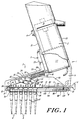
- the pipetter of the present invention has a boot-shaped housing 1 consisting of a handle section 2 and a lower or foot section 3.
- the handle section 2 carries both a push button 4 for initiating the pipetting action and a trigger 5 for removing disposable tips 6 which are frictionally secured to tip fittings 7 that project from the bottom 8 of the lower housing section 3.
- An actuating rod 11 carrying a knob 12 projects rearwardly from the lower section 3 and is secured at its forward end 15 within the housing 1 to an L-shaped bracket 14.
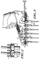
- the L-shaped bracket 14 in turn is connected to the rear most fitting 7b, and the several fittings 7 are connected together by a flexible strap 16. By pushing and pulling the knob 12 and rod 11 the fittings are moved between the positions of FIGS. 1 and 3.
- the details of the mechanisms for removing the tips 6 and for varying the spacing of the fittings 7 are described more fully below.
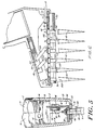
- the housing 1 of the pipetting system is made up of a pair of mating half shells 1a and 1b (see FIG. 5) which together form the handle section 2 and foot or lower section 3.
- the shells 1a and 1b include sidewalls 19 and 20 and front and back walls 21 and 22 that together define the handle section 2 and the lower section 3.
- the front, back and bottom of the lower section 3 are enclosed by the walls 21, 22 and 23, while the top of the bottom section forward of the handle is closed by wall 24.
- An elongated aperture 25 is provided in the bottom wall 23 and extends substantially the full length thereof symmetrical with respect to the parting line 26 that joins the two shells.
- the push button 4 which extends forwardly from the front edge of the handle section 2 is normally at the height of one's second finger when the handle is engaged while the trigger 5 which also extends forwardly from the front wall of the handle is at the height of the 4th and 5th fingers.
- the trigger is generally L-shaped having an upwardly extending section 28 along the front of the handle section 2 and base 29 which slides along the top wall 24 of the bottom section 3.
- the details of the pipetting system for drawing liquid in metered volumes into the tips 6 and for expelling the liquid from the tips is not part of the present invention and therefore is described only briefly herein.
- the system includes a cylinder 117 in the handle section 2 housing a plurality of parallel cylindrical chambers (not shown) that correspond in number to the number of fittings 7. In the embodiment shown, six fittings are included, but it should be appreciated that the number may vary.
- a piston (not shown) is slidably mounted in each chamber, and the pistons in turn are moved in tandem by a suitable electric motor M disposed in the handle section 2 above the cylinder 117.
- Each chamber is connected to one fitting 7 by a duct 115, only one of which is shown in FIGS. 1 and 3.
- Movement of the pistons by the motor M in one direction in their respective chambers draws liquid into the tips 6, and movement in the other direction expels the liquid from them.
- the motor in turn may be automatically controlled so as to program the volume of liquid drawn into and expelled from the tips during each actuation of the button 4 in the motor circuit.
- the button 4 is connected in the motor circuit to afford the operator control of the pipetting operation.
- the trigger 5 is integrally molded with a slide 30 that is disposed in the bottom section 3 of the housing immediately beneath top wall 24.
- the slide 30 has a recess 32 open to the rear and closed at its front end as shown at 36.
- a coil spring 38 is disposed in the recess 32 and bears against the end wall 36 at its front and against a barrier 40 carried in the rear of the half shell 1b of the housing.
- the slide 30 is carried by a pair of flanges 42 (one shown in FIG. 5) provided on each half shell of the housing and which are disposed in slots 44 in the side edges of the slide.
- the spring 38 urges the slide in a forward direction toward the front wall or toe 21 of the lower section of the housing, but the spring may be overridden by squeezing the trigger 5, which will compress the spring and draw the slide in the direction of rear wall 22 to the position of FIG. 6.
- the slide returns to the position shown in FIG. 1.
- a pair of parallel links 50 and 52 are pivotally secured to the forward end of the slide 30 by a pair of pivot pins 54 and 56 that extend through holes in the upper ends of the links and which span the slot 58 formed in the slide 30 into which the links extend.
- the other ends of the links 50 and 52 are connected by means of pivot pins 62 and 64 to the vertical flange 66 of stripper plate 68.
- the stripper plate 68 is confined to vertical translational motion in housing 1, and that motion is imparted to the stripper plate by actuation of slide 30.
- a tip fitting mounting plate 80 is secured immediately above the bottom wall 23 of the housing by slots 81 formed in each half shell 1a and 1b (see FIGS. 1, 3, and 6).
- the mounting plate 80 includes an elongated slot 82 narrower and somewhat shorter than the opening 25 in the bottom wall 23. All but one (fitting 7a) of the fittings 7 is slidably mounted in the slot so that they may be moved toward and away from the front wall 21 by means of the actuating rod 11 and its knob 12.
- the forward most fitting 7a is disposed in a separate opening 84 in the plate 80 and is immovable.
- the slot 82 forms a track for the fittings so as to guide their sliding motion to and fro along the bottom wall 23.
- each of the fittings disposed in the slot 82 has a truncated cone-shaped stem 94 having a diameter at its upper end which is larger than the width of slot 82, and consequently, the edges of the upper end of the stem bear against the lower surface of the mounting plate 80.
- each fitting (excepting 7a) has a waist 96 which extends through the slot 82. The waist also extends through a hole 90 in the strap 16.
- a thin retaining plate 92 surrounds the upper end of the fitting above the strap, and the assembly is held together on the mounting plate 80 by a C-shaped clip 93.
- The, upper end of each fitting carries a nipple 98 which in turn is connected to the lower end of duct 115. It will, of course, be appreciated that a passage extends through each fitting from the lower end of the stem 94 to the upper end of nipple 98, which passage is in communication with the duct passage.
- the fitting 7a is mounted in its opening 84 in the mounting plate 80 in precisely the same manner described above in connection with the other fittings 7 disposed in the slot 82.
- the only difference between the mounting of the other fittings and that of fitting 7a is that fitting 7a is rigidly secured in place and cannot move.
- the rear most fitting 7b in slot 82 is connected to the bracket 14 in turn connected to the rod 11.
- the horizontal flange 70 of the stripper plate 68 has a slot 100 formed therein through which the stems 94 of the fittings extend.
- the slot 100 in the flange does not interfere in any way with the sliding motion of the fittings in the mounting plate 80.
- the slot 100 is, however, narrower than the outer diameter of the upper ends 120 of the tips 6 which are mounted on the stems 94 (see FIGS. 4 and 5). Consequently, when the stripper plate is actuated by squeezing the trigger 5, the horizontal flange 70 moves downwardly toward the lower ends of the stems 94, and the sides engage the upper ends 120 of the tips to push them off the fittings 7.
- steps 110 are provided in the sides of the slot 100 in flange 70.
- the stripper plate 68 does not simultaneously engage all of the tips but rather their engagement is staggered so that a reduced force is required to eject them.
- the maximum spacing of the tips 7 may be varied by using straps 16 of different length and hole spacings. With longer straps and greater spacings, the spread of the fittings will be greater. It may or may not prove desirable when using straps of different length to use mounting plates 80 having slots 82 of different lengths as well. It is essential, however, that the fittings be maintained in parallel relationship so that the tips 6 mounted on them will remain parallel with one another. This is, of course, true whether the pipetter has six or a different number of channels.
- the tip fittings 7 are designed to slide from side to side in the slotted mounting plate 80, and their attachment to the flexible strap 16 is such that when the strap is pulled taught the tip fittings are set at their expanded spacing. To move the tip fittings to their closer spacing, it is only necessary to push the rod 11 into the housing 1, which causes the waists 96 of the tips 7 to engage one another as in FIGS. 1 and 2.
- the flexible ducts 115 which connect each of the fitting nipples 98 to the cylinder 117 allow the fittings to move freely on the mounting plate 80 without interference.
- the strap 16 is made of a flexible but non-stretchable material, the strap will fold accordion-like as shown in FIG. 2 when the tips are moved to the closely spaced position, and when the fittings are spread apart by means of the rod 11, the strap will be pulled flat and the non-stretchable character of the strap and the slot will limit the fitting separation to a precise dimension.
- a pair of notches 130 and 132 may be provided in the rod 11, which cooperation with a ball detent 134.
- the detent snaps into notch 130 the user will sense that the closely spaced relationship of the fittings has been established.
- the detent enters notch 132 the user will sense that the expanded spacing has been achieved.
- This detent arrangement may not be adopted as the length of the strap 16 and slot 82 as well as the width of the waists 96 may establish the maximum and minimum spacing for the fittings.
Landscapes
- Chemical & Material Sciences (AREA)
- Health & Medical Sciences (AREA)
- General Health & Medical Sciences (AREA)
- Life Sciences & Earth Sciences (AREA)
- Analytical Chemistry (AREA)
- Biochemistry (AREA)
- Physics & Mathematics (AREA)
- General Physics & Mathematics (AREA)
- Immunology (AREA)
- Pathology (AREA)
- Clinical Laboratory Science (AREA)
- Chemical Kinetics & Catalysis (AREA)
- Sampling And Sample Adjustment (AREA)
- Mobile Radio Communication Systems (AREA)
- Automatic Analysis And Handling Materials Therefor (AREA)
Claims (12)
- Handgehaltenes Mehrkanal-Pipettiersystem, umfassend ein Gehäuse (1) mit einem Handgriffabschnitt (2) und einem unteren Abschnitt (3), in welchem eine Mehrzahl von Pipettenspitzen (6) angebracht ist, wobei das Gehäuse außerdem eine Mehrzahl von Kanälen (115) einschließt, die mit den Pipettenspitzen (6) verbunden sind, Mittel (117) zum Ziehen eines Flüssigkeitsvolumens in jeden der Kanäle und Mittel zum Ausstoßen jedes Flüssigkeitsvolumens aus jedem der Kanäle durch dessen zugehörige Pipettenspitze (6), gekennzeichnet durch eine Montageplatte (80) in dem Gehäuse (1) mit einem darin befindlichen länglichen Schlitz (82), in welchem eine Mehrzahl von Pipettenspitzen-Aufsteckstutzen (7) verschiebbar montiert sind, wobei jeder Spitzen-Aufsteckstutzen (7) mit einem Kanal (115) verbunden ist, und durch Einstellmittel, die auf funktionelle Weise mit jedem der verschiebbaren Spitzen-Aufsteckstutzen (7) verbunden sind, um die Spitzen-Aufsteckstutzen (7) entlang dem Schlitz (82) in der Montageplatte (80) zu bewegen und dadurch den Abstand zwischen benachbarten Aufsteckstutzen (7) entlang der Montageplatte (80) zu verändern.
- Pipettiersystem nach Anspruch 1, dadurch gekennzeichnet, daß die Einstellmittel Mittel zur gleichzeitigen Veränderung des Abstands zwischen sämtlichen Spitzen-Aufsteckstutzen (7) beinhalten.
- Pipettiersystem nach Anspruch 2, dadurch gekennzeichnet, daß die Einstellmittel ein flexibles Band (16), das an den Spitzen-Aufsteckstutzen (7) befestigt ist, um eine Aufsteckstutzenreihe auszubilden, sowie einen Betätigungsstab (11) umfassen, der an einem Ende der Reihe zur Verlängerung dieser Reihe durch Straffen des Bandes (16) und zur Verkürzung der Reihe durch Falten des Bandes (16) angebracht ist.
- Pipettiersystem nach Anspruch 3, dadurch gekennzeichnet, daß das flexible Band (16) aus einem nicht dehnbaren Material gefertigt ist.
- Pipettiersystem nach Anspruch 3 oder Anspruch 4, dadurch gekennzeichnet, daß sich auf dem Stab (11) voneinander beabstandete Kerben (130, 132) befinden und in dem Gehäuse (1) einrückbare Arretierungsmittel (134) zum Eingreifen in die Kerben (130, 132) zur Sicherung der Anordnung in ausgewählten Positionen montiert sind.
- Pipettiersystem nach irgendeinem der vorhergehenden Ansprüche, gekennzeichnet durch eine Abstreifeinrichtung zum Entfernen von an den Spitzen-Aufsteckstutzen (7) angebrachten Spitzen (6).
- Pipettiersystem nach Anspruch 6, bei dem die Abstreifeinrichtung einen an dem Gehäuse (1) angebrachten Auslöser (5), eine an dem Auslöser (5) befestigte und den Auslöser in eine erste Position ablenkende Feder (38), eine beweglich in dem Gehäuse (1) montierte Abstreifplatte (68), sowie Verbindungsstücke (50, 52) umfaßt, die zwischen dem Auslöser (5) und der Abstreifplatte (68) befestigt sind und dazu dienen, die Platte zu betätigen, um die Spitzen (6) zu erfassen und von den Spitzen-Aufsteckstutzen (7) abzuwerten.
- Pipettiersystem nach Anspruch 7, dadurch gekennzeichnet, daß die Abstreifplatte (68) einen Schlitz (100) enthält und sich die Spitzen-Aufsteckstutzen (7) durch diesen Schlitz erstrecken.
- Pipettiersystem nach Anspruch 8, dadurch gekennzeichnet, daß die Abstreifplatte (68) abgestufte Kanten (110) um den Schlitz (100) herum aufweist, welche bewirken, daß die Platte (68) bestimmte Spitzen (6) nacheinander erfaßt, wenn der Auslöser (5) betätigt wird.
- Pipettiersystem nach irgendeinem der vorhergehenden Ansprüche, dadurch gekennzeichnet, daß die Montageplatte (80) gerade ist, um sämtliche der Spitzen-Aufsteckstutzen (7) in einer Reihe auszurichten.
- Pipettiersystem nach Anspruch 1, dadurch gekennzeichnet, daß der untere Abschnitt (3) des Gehäuses (1) mit einem Ende mit dem Handgriffabschnitt verbunden ist und sich von diesem nach vorn erstreckt.
- Pipettiersystem nach Anspruch 1, dadurch gekennzeichnet, daß die Einstellmittel ein flexibles Band (16) umfassen, das faltbar ist, wobei dieses Band (16) einzelne Verbindungen zu den Spitzen-Aufsteckstutzen (7) aufweist, welche es ermöglichen, daß die Aufsteckstutzen um einen Maximalabstand separiert werden, der von dem Abstand zwischen den Verbindungsstellen der Aufsteckstutzen mit dem Band (16) bestimmt ist.
Applications Claiming Priority (3)
| Application Number | Priority Date | Filing Date | Title |
|---|---|---|---|
| US385234 | 1989-07-25 | ||
| US07/385,234 US5061449A (en) | 1989-07-25 | 1989-07-25 | Expandable multi-channel pipetter |
| PCT/US1990/003777 WO1991001181A1 (en) | 1989-07-25 | 1990-07-05 | Multi-channel pipetter |
Publications (3)
| Publication Number | Publication Date |
|---|---|
| EP0483225A1 EP0483225A1 (de) | 1992-05-06 |
| EP0483225A4 EP0483225A4 (en) | 1992-07-08 |
| EP0483225B1 true EP0483225B1 (de) | 1996-06-05 |
Family
ID=23520580
Family Applications (1)
| Application Number | Title | Priority Date | Filing Date |
|---|---|---|---|
| EP90911212A Expired - Lifetime EP0483225B1 (de) | 1989-07-25 | 1990-07-05 | Handgehaltene mehrkanälige pipettierungsvorrichtung |
Country Status (7)
| Country | Link |
|---|---|
| US (1) | US5061449A (de) |
| EP (1) | EP0483225B1 (de) |
| JP (1) | JP3048245B2 (de) |
| CA (1) | CA2063816C (de) |
| DE (1) | DE69027325T2 (de) |
| FI (1) | FI97700C (de) |
| WO (1) | WO1991001181A1 (de) |
Families Citing this family (58)
| Publication number | Priority date | Publication date | Assignee | Title |
|---|---|---|---|---|
| GB2249172A (en) * | 1990-10-26 | 1992-04-29 | N Proizv Ob Biolog Priborostro | Multichannel pipette |
| US5827745A (en) * | 1993-03-29 | 1998-10-27 | Astle; Thomas W. | Micropipette tip loading and unloading device and method and tip package |
| US5540889A (en) * | 1994-05-11 | 1996-07-30 | Whitehead Institute For Biomedical Research | Apparatus and method for a highly parallel pipetter |
| US6800452B1 (en) * | 1994-08-08 | 2004-10-05 | Science Applications International Corporation | Automated methods for simultaneously performing a plurality of signal-based assays |
| FR2739935B1 (fr) * | 1995-10-12 | 1997-12-19 | Genomic Sa | Dispositif pour le transfert d'echantillons de micro-quantites de liquides |
| US6231813B1 (en) * | 1997-09-16 | 2001-05-15 | Invitrogen Corporation | Gel loading adapter |
| US6415669B1 (en) * | 1998-04-09 | 2002-07-09 | Ccs Packard, Inc. | Dispensing apparatus having means for loading pipette tips in a dispense head |
| DE19845950C1 (de) * | 1998-10-06 | 2000-03-23 | Eppendorf Geraetebau Netheler | Pipettiersystem mit einer Pipettiervorrichtung und mindestens einer daran lösbar befestigten Pipettenspitze |
| US6235244B1 (en) | 1998-12-14 | 2001-05-22 | Matrix Technologies Corp. | Uniformly expandable multi-channel pipettor |
| EP1150772B1 (de) * | 1998-12-15 | 2008-01-02 | Matrix Technologies Corporation | Einheitlich expandierbares vielfach-kanal-pipettiergerät |
| US6258324B1 (en) * | 1999-03-15 | 2001-07-10 | Felix H. Yiu | Pipette dispensing block |
| JP2001033463A (ja) | 1999-07-23 | 2001-02-09 | Cosmo Tec:Kk | 液体分注装置 |
| US6244119B1 (en) * | 1999-08-03 | 2001-06-12 | Wallac Oy | Multichannel pipette system and pipette tips therefor |
| JP3723021B2 (ja) * | 1999-09-30 | 2005-12-07 | 富士写真フイルム株式会社 | マイクロアレイチップ製造装置 |
| US6451263B1 (en) * | 1999-11-04 | 2002-09-17 | Helena Laboratories Corporation | Pipette adapter |
| DE19962689C2 (de) * | 1999-12-23 | 2002-02-07 | Tecconsult & Trading Ohg | Vorrichtung zum Auftragen von flüssigen Proben mittels Pipetten auf Platten, Folie o. dgl. |
| DE20006547U1 (de) * | 2000-04-08 | 2001-08-16 | MWG-BIOTECH AG, 85560 Ebersberg | Verstellvorrichtung |
| US6387330B1 (en) * | 2000-04-12 | 2002-05-14 | George Steven Bova | Method and apparatus for storing and dispensing reagents |
| DE10022693C1 (de) * | 2000-05-05 | 2001-10-11 | Cybio Instr Gmbh | Pipettierautomat mit einem Einreihigen-Mehrkanal-Pipettierkopf |
| US6982063B2 (en) * | 2001-05-25 | 2006-01-03 | Matrix Technologies Corp | Automated pipetting system |
| JP3733942B2 (ja) * | 2002-10-03 | 2006-01-11 | 松下電器産業株式会社 | 分注装置および分注装置における分注ティップの離脱方法 |
| US20040071602A1 (en) * | 2002-10-15 | 2004-04-15 | Yiu Felix H. | Pipettor head adapter |
| US20040253148A1 (en) * | 2003-06-16 | 2004-12-16 | Leaton John R. | Multiple probe expansion (MPX™) accessory device for manual, semi-automated and automated liquid handling equipment federally sponsored research |
| US7396512B2 (en) | 2003-11-04 | 2008-07-08 | Drummond Scientific Company | Automatic precision non-contact open-loop fluid dispensing |
| US7968056B2 (en) * | 2004-05-10 | 2011-06-28 | Joe Stockwell | Method and apparatus for transferring pipette tips |
| DE102005030196B3 (de) * | 2005-06-29 | 2007-02-01 | Eppendorf Ag | Mehrkanaldosiervorrichtung |
| US20070092410A1 (en) * | 2005-10-26 | 2007-04-26 | Ricker Robert D | Device for pipetting solution from one plate format to a different plate platform using movable position pipette tips |
| US8663577B2 (en) * | 2006-07-12 | 2014-03-04 | National Institute Of Advanced Industrial Science And Technology | Variable pitch array spotter |
| WO2008007556A1 (en) * | 2006-07-12 | 2008-01-17 | National Institute Of Advanced Industrial Science And Technology | Variable pitch array spotter |
| US20090071267A1 (en) * | 2007-09-17 | 2009-03-19 | Greg Mathus | Pipette tip ejection mechanism |
| US8088593B2 (en) | 2007-10-02 | 2012-01-03 | Theranos, Inc. | Modular point-of-care devices, systems, and uses thereof |
| US7947234B2 (en) * | 2007-10-17 | 2011-05-24 | Rainin Instrument, Llc | Liquid end assembly for a handheld multichannel pipette with adjustable nozzle spacing |
| USD596755S1 (en) | 2008-04-04 | 2009-07-21 | Viaflo Corporation | Multi-channel pipette having repositionable tip fittings |
| US8029742B2 (en) * | 2008-05-05 | 2011-10-04 | Integra Biosciences Corp. | Multi-channel pipettor with repositionable tips |
| US9339810B2 (en) | 2008-05-05 | 2016-05-17 | Integra Biosciences Ag | Multi-channel pipettor with repositionable tips |
| US8333925B2 (en) * | 2009-06-05 | 2012-12-18 | Jeffrey Michael Holmes | Ergonomic pipetting workstation |
| US8196375B2 (en) * | 2010-05-27 | 2012-06-12 | Matrix Technologies Corporation | Handheld tube capper/decapper |
| CN106323875B (zh) | 2011-01-21 | 2019-07-09 | 西拉诺斯知识产权有限责任公司 | 样品使用最大化的系统和方法 |
| US8435738B2 (en) | 2011-09-25 | 2013-05-07 | Theranos, Inc. | Systems and methods for multi-analysis |
| US9632102B2 (en) | 2011-09-25 | 2017-04-25 | Theranos, Inc. | Systems and methods for multi-purpose analysis |
| US8475739B2 (en) | 2011-09-25 | 2013-07-02 | Theranos, Inc. | Systems and methods for fluid handling |
| US9664702B2 (en) | 2011-09-25 | 2017-05-30 | Theranos, Inc. | Fluid handling apparatus and configurations |
| US8840838B2 (en) | 2011-09-25 | 2014-09-23 | Theranos, Inc. | Centrifuge configurations |
| US9619627B2 (en) | 2011-09-25 | 2017-04-11 | Theranos, Inc. | Systems and methods for collecting and transmitting assay results |
| US20140170735A1 (en) | 2011-09-25 | 2014-06-19 | Elizabeth A. Holmes | Systems and methods for multi-analysis |
| US9268915B2 (en) | 2011-09-25 | 2016-02-23 | Theranos, Inc. | Systems and methods for diagnosis or treatment |
| US9250229B2 (en) | 2011-09-25 | 2016-02-02 | Theranos, Inc. | Systems and methods for multi-analysis |
| US9810704B2 (en) | 2013-02-18 | 2017-11-07 | Theranos, Inc. | Systems and methods for multi-analysis |
| US10012664B2 (en) | 2011-09-25 | 2018-07-03 | Theranos Ip Company, Llc | Systems and methods for fluid and component handling |
| FI20135498L (fi) * | 2013-05-13 | 2014-11-14 | Thermo Fisher Scientific Oy | Monikanavapipetti |
| US11545241B1 (en) | 2013-09-07 | 2023-01-03 | Labrador Diagnostics Llc | Systems and methods for analyte testing and data management |
| USD772426S1 (en) * | 2014-01-13 | 2016-11-22 | Gilson, Inc. | Pipette system cartridge |
| CN108025306B (zh) * | 2016-01-07 | 2020-11-20 | 株式会社爱安德 | 多通道移液器 |
| US10758909B2 (en) * | 2017-07-25 | 2020-09-01 | Thomas A. HEDGLIN | Device to assist in manual transfer of pipette tips |
| WO2019151973A1 (en) * | 2018-01-30 | 2019-08-08 | Hewlett-Packard Development Company, L.P. | Fluidic ejection systems with titration plate form factors |
| EP3932557B1 (de) | 2020-07-02 | 2023-11-15 | Eppendorf SE | Mehrkanalpipettierkopf |
| GB2597505A (en) * | 2020-07-24 | 2022-02-02 | The Francis Crick Institute Ltd | Tip ejector block and multi-channel laboratory tool |
| CN115382592B (zh) * | 2022-09-09 | 2024-08-09 | 科来思(深圳)科技有限公司 | 间距可调的双针式移液装置 |
Family Cites Families (6)
| Publication number | Priority date | Publication date | Assignee | Title |
|---|---|---|---|---|
| NL6504453A (de) * | 1965-04-07 | 1966-10-10 | ||
| US4599220A (en) * | 1982-02-16 | 1986-07-08 | Yonkers Edward H | Multi-channel pipetter |
| CH671526A5 (de) * | 1985-12-17 | 1989-09-15 | Hamilton Bonaduz Ag | |
| US4824642A (en) * | 1986-10-21 | 1989-04-25 | Costar Corporation | Multi-channel pipetter |
| US4779467A (en) * | 1987-01-28 | 1988-10-25 | Rainin Instrument Co., Inc. | Liquid-end assembly for multichannel air-displacement pipette |
| CA1321940C (en) * | 1987-05-02 | 1993-09-07 | Teruaki Itoh | Apparatus for distributing sample liquid |
-
1989
- 1989-07-25 US US07/385,234 patent/US5061449A/en not_active Expired - Lifetime
-
1990
- 1990-07-05 DE DE69027325T patent/DE69027325T2/de not_active Expired - Lifetime
- 1990-07-05 CA CA002063816A patent/CA2063816C/en not_active Expired - Lifetime
- 1990-07-05 EP EP90911212A patent/EP0483225B1/de not_active Expired - Lifetime
- 1990-07-05 JP JP2510736A patent/JP3048245B2/ja not_active Expired - Lifetime
- 1990-07-05 WO PCT/US1990/003777 patent/WO1991001181A1/en not_active Ceased
-
1992
- 1992-01-20 FI FI920248A patent/FI97700C/fi active
Also Published As
| Publication number | Publication date |
|---|---|
| FI920248A0 (fi) | 1992-01-20 |
| JP3048245B2 (ja) | 2000-06-05 |
| CA2063816C (en) | 2001-10-23 |
| US5061449A (en) | 1991-10-29 |
| EP0483225A1 (de) | 1992-05-06 |
| CA2063816A1 (en) | 1991-01-26 |
| DE69027325D1 (de) | 1996-07-11 |
| EP0483225A4 (en) | 1992-07-08 |
| DE69027325T2 (de) | 1996-10-31 |
| JPH05500630A (ja) | 1993-02-12 |
| FI97700B (fi) | 1996-10-31 |
| WO1991001181A1 (en) | 1991-02-07 |
| FI97700C (fi) | 1998-05-26 |
Similar Documents
| Publication | Publication Date | Title |
|---|---|---|
| US5061449A (en) | Expandable multi-channel pipetter | |
| US5057281A (en) | Adjustable multi-channel pipetter | |
| US6235244B1 (en) | Uniformly expandable multi-channel pipettor | |
| CA1039246A (en) | Hand-held micropipettor with improved accuracy of liquid volumes transferred | |
| US4099548A (en) | Hand-held pipette for repetitively dispensing precise volumes of liquid | |
| EP0265028B1 (de) | Mehrkanal-Pipette | |
| US4009611A (en) | Hand-held micropipettor with improved pipette tip ejector | |
| US4599220A (en) | Multi-channel pipetter | |
| EP0421785A2 (de) | Pipettiervorrichtung | |
| KR101449086B1 (ko) | 피스톤의 전후 운동에 의한 샘플링을 제공하는 피펫 | |
| US6997067B2 (en) | Liquid sample pipette with detachable ejector | |
| WO2022018434A1 (en) | Tip ejector block and multi-channel laboratory tool | |
| KR100718033B1 (ko) | 콘 이젝터가 있는 피펫 | |
| EP1150772B1 (de) | Einheitlich expandierbares vielfach-kanal-pipettiergerät | |
| AU2019430111B2 (en) | Exfoliative cell collection device for uterus examination | |
| GB2115719A (en) | Multi-channel pipetter | |
| GB2161398A (en) | Pipette | |
| CN215506858U (zh) | 一种移液枪头转移装置 | |
| EP1569754B1 (de) | Mehrkanalpipette | |
| GB2048712A (en) | A Micropipette for Repetitive Delivering of small Constant Amounts of Liquid and/or Multiples Thereof | |
| GB2249172A (en) | Multichannel pipette | |
| AU2006201347A1 (en) | Pipette with tip ejector |
Legal Events
| Date | Code | Title | Description |
|---|---|---|---|
| PUAI | Public reference made under article 153(3) epc to a published international application that has entered the european phase |
Free format text: ORIGINAL CODE: 0009012 |
|
| 17P | Request for examination filed |
Effective date: 19920117 |
|
| AK | Designated contracting states |
Kind code of ref document: A1 Designated state(s): DE ES FR GB IT NL |
|
| A4 | Supplementary search report drawn up and despatched |
Effective date: 19920518 |
|
| AK | Designated contracting states |
Kind code of ref document: A4 Designated state(s): DE ES FR GB IT NL |
|
| 17Q | First examination report despatched |
Effective date: 19930628 |
|
| GRAH | Despatch of communication of intention to grant a patent |
Free format text: ORIGINAL CODE: EPIDOS IGRA |
|
| GRAA | (expected) grant |
Free format text: ORIGINAL CODE: 0009210 |
|
| AK | Designated contracting states |
Kind code of ref document: B1 Designated state(s): DE ES FR GB IT NL |
|
| PG25 | Lapsed in a contracting state [announced via postgrant information from national office to epo] |
Ref country code: IT Free format text: LAPSE BECAUSE OF FAILURE TO SUBMIT A TRANSLATION OF THE DESCRIPTION OR TO PAY THE FEE WITHIN THE PRESCRIBED TIME-LIMIT;WARNING: LAPSES OF ITALIAN PATENTS WITH EFFECTIVE DATE BEFORE 2007 MAY HAVE OCCURRED AT ANY TIME BEFORE 2007. THE CORRECT EFFECTIVE DATE MAY BE DIFFERENT FROM THE ONE RECORDED. Effective date: 19960605 Ref country code: FR Effective date: 19960605 |
|
| REF | Corresponds to: |
Ref document number: 69027325 Country of ref document: DE Date of ref document: 19960711 |
|
| PGFP | Annual fee paid to national office [announced via postgrant information from national office to epo] |
Ref country code: FR Payment date: 19960808 Year of fee payment: 7 |
|
| PG25 | Lapsed in a contracting state [announced via postgrant information from national office to epo] |
Ref country code: ES Free format text: LAPSE BECAUSE OF FAILURE TO SUBMIT A TRANSLATION OF THE DESCRIPTION OR TO PAY THE FEE WITHIN THE PRESCRIBED TIME-LIMIT Effective date: 19960916 |
|
| EN | Fr: translation not filed | ||
| PLBE | No opposition filed within time limit |
Free format text: ORIGINAL CODE: 0009261 |
|
| STAA | Information on the status of an ep patent application or granted ep patent |
Free format text: STATUS: NO OPPOSITION FILED WITHIN TIME LIMIT |
|
| 26N | No opposition filed | ||
| PGFP | Annual fee paid to national office [announced via postgrant information from national office to epo] |
Ref country code: ES Payment date: 19970730 Year of fee payment: 8 |
|
| REG | Reference to a national code |
Ref country code: GB Ref legal event code: IF02 |
|
| PGFP | Annual fee paid to national office [announced via postgrant information from national office to epo] |
Ref country code: NL Payment date: 20090705 Year of fee payment: 20 Ref country code: DE Payment date: 20090702 Year of fee payment: 20 Ref country code: GB Payment date: 20090701 Year of fee payment: 20 |
|
| REG | Reference to a national code |
Ref country code: NL Ref legal event code: V4 Effective date: 20100705 |
|
| REG | Reference to a national code |
Ref country code: GB Ref legal event code: PE20 Expiry date: 20100704 |
|
| PG25 | Lapsed in a contracting state [announced via postgrant information from national office to epo] |
Ref country code: NL Free format text: LAPSE BECAUSE OF EXPIRATION OF PROTECTION Effective date: 20100705 |
|
| PG25 | Lapsed in a contracting state [announced via postgrant information from national office to epo] |
Ref country code: GB Free format text: LAPSE BECAUSE OF EXPIRATION OF PROTECTION Effective date: 20100704 |
|
| PG25 | Lapsed in a contracting state [announced via postgrant information from national office to epo] |
Ref country code: DE Free format text: LAPSE BECAUSE OF EXPIRATION OF PROTECTION Effective date: 20100705 |