EP0482425B1 - Device for measuring current, especially current and voltage, on conductors of a single or multiphase system - Google Patents
Device for measuring current, especially current and voltage, on conductors of a single or multiphase system Download PDFInfo
- Publication number
- EP0482425B1 EP0482425B1 EP91117196A EP91117196A EP0482425B1 EP 0482425 B1 EP0482425 B1 EP 0482425B1 EP 91117196 A EP91117196 A EP 91117196A EP 91117196 A EP91117196 A EP 91117196A EP 0482425 B1 EP0482425 B1 EP 0482425B1
- Authority
- EP
- European Patent Office
- Prior art keywords
- air
- housing
- equipment
- section
- voltage
- Prior art date
- Legal status (The legal status is an assumption and is not a legal conclusion. Google has not performed a legal analysis and makes no representation as to the accuracy of the status listed.)
- Expired - Lifetime
Links
Images
Classifications
-
- G—PHYSICS
- G01—MEASURING; TESTING
- G01R—MEASURING ELECTRIC VARIABLES; MEASURING MAGNETIC VARIABLES
- G01R1/00—Details of instruments or arrangements of the types included in groups G01R5/00 - G01R13/00 and G01R31/00
- G01R1/20—Modifications of basic electric elements for use in electric measuring instruments; Structural combinations of such elements with such instruments
- G01R1/22—Tong testers acting as secondary windings of current transformers
Definitions
- the invention relates to a device for measuring current, preferably current and voltage, on conductors of a single-phase or multiphase system, in particular conductors of low-voltage power supply systems, which device has the features of the preamble of claim 1.
- the housing has a U-like shape. In each of the free end faces of the two legs of the device housing, a straight channel for receiving one of the two legs of a U-shaped air coil opens.
- the device housing together with this air coil comprises the busbar, the voltage and current flow of which are to be measured.
- a bridge made of magnetically conductive metal arranged in the yoke part of the device housing connects the two ends of the air coil.
- An electrode arranged in the device housing is capacitively coupled to the busbar when the device housing is placed on the busbar and serves as a voltage sensor.
- Such a device can also be used to measure current and voltage on conductors other than busbars, in particular also on cables. Both the Handling as well as the achievable measuring accuracy are not always satisfactory.
- the first part of the air coil is arranged on a dimensionally stable winding support, which has a C-like shape with a straight yoke section and straight, shorter legs compared to the yoke section, of which one is firmly connected to the device housing.
- the second part of the air coil is carried by a dimensionally stable winding support, which consists of a rectilinear rod, which is pivotally connected to the device housing in the region of its one end in such a way that it rests in one position on the ends of the legs of the first winding support and this supplemented to a closed rectangle, and in its other pivot position keeps the hook formed by the other winding support open.
- the invention is therefore based on the object of providing a device of the type mentioned which is easier to handle than the known devices when used and therefore opens up a wide range of possible uses and also because of a high measuring accuracy. This object is achieved by a device having the features of claim 1.
- the device according to the invention can be used on conductors of any design , for example also conveniently attach to a cable and also remove it from this conductor again.
- conductors of any design for example also conveniently attach to a cable and also remove it from this conductor again.
- part of the air coil that is movable relative to the device housing needs to be brought into a position from the position in which it adjoins the first section and the hook formed by the latter is supplemented to form a U-shaped bracket which the hook for inserting the conductor is open.
- the device can also be designed such that the hook formed by the first section of the air coil is normally open and that it is only supplemented by the second section to form the U-shaped bracket during the measurement.
- the simple handling of the device according to the invention even makes it possible to handle the device with only one hand. It is therefore particularly suitable for measurements on cables and busbars in low-voltage distribution systems, e.g. cable distribution cabinets, house connection boxes and power distribution systems, but also on equipment such as transformers, motors or generators. Because only the insulated device housing is touched by hand for handling, the device can be attached to and removed from the conductor to be measured while it is live.
- the air coil is not closed by a bridge made of magnetically conductive material, i.e. ferromagnetic material, but rather by bringing the ends of its sections into a position in which they connect to one another, the desired measurement accuracy is obtained for the current measurement, specifically regardless of the position of the coil relative to the conductor, since the air coil is one or two layers, the active area of each turn is the same, the pitch of the turns is at least almost constant and the number of turns is more than 400.
- An electrode which is capacitively coupled to the conductor, can be provided in the device housing as a voltage sensor.
- a terminal that can be attached to the conductor is provided, which is connected via a flexible cable to the signal processing electronics contained in the device housing.
- the two housings containing the first and second sections of the air coil are preferably of identical design, so that they each form one half of the U-shaped bracket.
- the air coil adapts very well to a cable.
- a manually operable drive element is provided outside the device housing. that can have the shape of a push button or slide, for example.
- manual drive is preferably provided at least one preloaded spring which tries to keep the movable section or sections in one of the two end positions. For example, if the spring holds the movable section or sections in the position resulting in a closed bracket, then the drive member need only be moved against the force of the return spring to open the bracket.
- the signal processing electronics preferably have an output for a signal which represents the power, preferably the active power.
- the signal processing electronics deliver the output signals in the form of impressed currents.
- the measured values could also be output in digital form.
- the output signals supplied by the signal processing electronics can be fed via a connecting line to a device which displays and / or prints out the measured values.
- a device which displays and / or prints out the measured values.
- the embodiment of the device according to the invention shown in FIGS. 1 to 3 has a device housing 101 made of plastic, which differs from a cuboid shape in that the part serving as a handle 101 'has a smaller width than the rest of the part, which is also opposite in the embodiment the handle part 101 'is angled. This bend enables the handle part 101 'to be brought into a position approximately parallel to the conductor to be measured, which is very advantageous, for example, when measuring in a cable distribution cabinet.
- About the handle portion 101 'facing away from the wider part of the device housing 101 are two dimensionally stable coil housings 102 and 103, each having a straight section and an adjoining curved section in the form of a quarter circle.
- the two rectilinear sections are arranged parallel to one another in such a way that there is no air gap or at most a small air gap between the free end faces of their curved sections if these curved sections point towards one another and together with the rectilinear sections form a U-shaped bracket with a semicircular yoke section.
- the two identical coil housings 102 and 103 like the device housing 101, are each composed of two half shells made of plastic.
- the end sections of the two coil housings 102 and 103 that are located inside the device housing 101 are mounted in the device housing 101 so that they can rotate about their longitudinal axis, but are not displaceable in the axial direction.
- One O-ring 113 provides a seal between the coil housing and the device housing 101.
- One preloaded spring 114 which surrounds each coil housing 102 and 103 in its end section mounted in the device housing 101, is on the one hand on the device housing 101 and on the other hand supported on a radial projection 115 of the coil housing. These pretensioned springs 114 try to hold both coil housings 102 and 103 in the rotational position shown in FIG. 1, in which the U-shaped bracket is closed. In this rotational position, an additional projection 116 stops on a material section of the device housing 101.
- each of the two coil housings 102 and 103 lying in the device housing 101 carries a disk 117 with a radial slot 118 into which a pin 119 engages.
- the two radial slots 118 extend in opposite directions.
- the two pins 119 protrude from a slide 120 which is mounted in the device housing 101 so as to be displaceable in the transverse direction and which at one end forms a push button 121 which projects laterally from the device housing 101 in the region of the wider section.
- Each bobbin case 102 and 103 contains a plastic bobbin on which a first section 123a and a second section 123d are wound in one layer such that the active area of each turn is the same and the pitch the turns are at least almost constant.
- the two identical sections 123a and 123d are parts of an air coil 123 which has more than 400 turns.
- a connecting line runs from the turn adjacent to the free end face of the coil housing of both the first section 123a and the second section 123d of the air coil 123 back into the device housing 101, where these two connecting lines are connected to one another.
- the bracket is closed, the second section 123d forms a continuation of the section 123a of the air coil 123 and vice versa.
- a third section 123c of the air coil 123 which, as shown in FIG. 1, closes the ends of the sections 123a and 123d in the device housing 101 to form a ring coil.
- two connecting lines lead to signal processing electronics 109 arranged in the handle part 101 'on a carrier plate. These two connecting lines are connected to the beginning or end of the air coil 123 and therefore lead the signal processing electronics 109 to the voltage induced in the air coil 123 to, which is a measure of the current intensity of the conductor wrapped in the air coil 123.
- a cable bushing 126 is provided on the end face of the device housing 101 facing away from the coil housings 102 and 103 for a connecting cable.
- a safety socket 111 is arranged for receiving a safety plug 112 is arranged at one end of a laboratory measuring cable 108, the other end of which is connected to a fully insulated terminal serving as a voltage tap.
- the signal processing electronics 109 when this terminal carries the voltage of the conductor enclosed by the air coil 123, in addition to the current measured value, also the voltage measured value and the active powers in the form of impressed currents.
- the measuring ranges are for the voltage in the range up to 300 volts, for current measurement in the range up to 630 amperes and the active power in the range up to 157 kW.
Landscapes
- Engineering & Computer Science (AREA)
- Power Engineering (AREA)
- Physics & Mathematics (AREA)
- General Physics & Mathematics (AREA)
- Measuring Instrument Details And Bridges, And Automatic Balancing Devices (AREA)
- Measurement Of Current Or Voltage (AREA)
- General Induction Heating (AREA)
- Electrical Discharge Machining, Electrochemical Machining, And Combined Machining (AREA)
- Transformers For Measuring Instruments (AREA)
Abstract
Description
Die Erfindung betrifft ein Gerät zur Messung von Strom, vorzugsweise von Strom und Spannung, an Leitern eines ein- oder mehrphasigen Systems, insbesondere Leitern von Niederspannungs-Energieversorgungsanlagen, welches Gerät die Merkmale des Oberbegriffes des Anspruches 1 aufweist.The invention relates to a device for measuring current, preferably current and voltage, on conductors of a single-phase or multiphase system, in particular conductors of low-voltage power supply systems, which device has the features of the preamble of
Bei einem bekannten Gerät (DE-A-3 707 707) zur Messung von Strom und Spannung an Sammelschienen hat das Gehäuse eine U-artige Form. In den freien Endflächen der beiden Schenkel des Gerätegehäuses mündet je ein geradliniger Kanal für die Aufnahme je eines der beiden Schenkel einer U-förmigen Luftspule. Das Gerätegehäuse umfaßt zusammen mit dieser Luftspule die Sammelschiene, deren Spannung und Stromfluß gemessen werden soll. Eine im Jochteil des Gerätegehäuses angeordnete Brücke aus magnetisch leitendem Metall verbindet die beiden Enden der Luftspule. Eine im Gerätegehäuse angeordnete Elektrode ist an die Sammelschiene kapaziv angekoppelt, wenn das Gerätegehäuse auf die Sammelschiene aufgesetzt ist, und dient als Spannungsensor. Zwar kann ein derartiges Gerät auch zur Messung von Strom und Spannung an anderen Leitern als Sammelschienen, insbesondere auch an Kabeln, eingesetzt werden. Sowohl die Handhabung als auch die erzielbare Meßgenauigkeit sind jedoch dann nicht immer zufriedenstellend.In a known device (DE-A-3 707 707) for measuring current and voltage on busbars, the housing has a U-like shape. In each of the free end faces of the two legs of the device housing, a straight channel for receiving one of the two legs of a U-shaped air coil opens. The device housing together with this air coil comprises the busbar, the voltage and current flow of which are to be measured. A bridge made of magnetically conductive metal arranged in the yoke part of the device housing connects the two ends of the air coil. An electrode arranged in the device housing is capacitively coupled to the busbar when the device housing is placed on the busbar and serves as a voltage sensor. Such a device can also be used to measure current and voltage on conductors other than busbars, in particular also on cables. Both the Handling as well as the achievable measuring accuracy are not always satisfactory.
Bei einem bekannten Gerät der eingangs genannten Art (DE-A-1 905 468) ist der erste Teil der Luftspule auf einem formstabilen Wicklungsträger angeordnet, der eine C-artige Form mit geradlinigem Jochabschnitt und geradlinigen, im Vergleich zum Jochabschnitt kürzeren Schenkeln hat, wovon der eine fest mit dem Gerätegehäuse verbunden ist. Der zweite Teil der Luftspule wird von einem formstabilen Wicklungsträger, der aus einem geradlinigen Stab besteht, getragen, der im Bereich seines einen Endes derart schwenkbar mit dem Gerätegehäuse verbunden ist, daß er in seiner einen Position an den Enden der Schenkel des ersten Wicklungsträgers anliegt und diesen zu einem geschlossenen Rechteck ergänzt, und in seiner anderen Schwenklage den vom anderen Wicklungsträger gebildeten Haken offenhält. Auch die Handhabung dieses Gerätes und damit seine Einsatzmöglichkeiten lassen Wünsche offen. Beispielsweise werden für die beiden Schenkel sowie den Jochteil des ersten Wicklungsträgers Teilspulen benötigt, die in den Eckbereichen Abschirmungen erforderlich machen. Außerdem muß der zweite Wicklungsträger, um das Gerät an einen Leiter ansetzen zu können, vom freien Ende des ersten Wicklungsträgers manuell weggeschwenkt werden, was nicht mit der das Gerätegehäuse festhaltenden Hand möglich ist. Weiterhin ist nachteilig, daß der Schwenkwinkel des ersten Wicklungsträgers groß gewählt werden muß, wenn an einem Leiter mit entsprechend großem Durchmesser eine Messung durchgeführt werden soll.In a known device of the type mentioned (DE-A-1 905 468), the first part of the air coil is arranged on a dimensionally stable winding support, which has a C-like shape with a straight yoke section and straight, shorter legs compared to the yoke section, of which one is firmly connected to the device housing. The second part of the air coil is carried by a dimensionally stable winding support, which consists of a rectilinear rod, which is pivotally connected to the device housing in the region of its one end in such a way that it rests in one position on the ends of the legs of the first winding support and this supplemented to a closed rectangle, and in its other pivot position keeps the hook formed by the other winding support open. The handling of this device and its possible uses leave nothing to be desired. For example, partial coils are required for the two legs and the yoke part of the first winding support, which require shielding in the corner areas. In addition, in order to be able to attach the device to a conductor, the second winding support must be manually pivoted away from the free end of the first winding support, which is not possible with the hand holding the device housing. Another disadvantage is that the swivel angle of the first winding support must be chosen large if a measurement is to be carried out on a conductor with a correspondingly large diameter.
Der Erfindung liegt daher die Aufgabe zugrunde, ein Gerät der eingangs genannten Art zu schaffen, das beim Gebrauch besser als die bekannten Geräte zu handhaben ist und deshalb sowie wegen einer hohen Meßgenauigkeit vielfältige Einsatzmöglichkeiten eröffnet. Diese Aufgabe löst ein Gerät mit den Merkmalen des Anspruches 1.The invention is therefore based on the object of providing a device of the type mentioned which is easier to handle than the known devices when used and therefore opens up a wide range of possible uses and also because of a high measuring accuracy. This object is achieved by a device having the features of
Dadurch, daß von den beiden Gehäusen, welche den ersten bzw. zweiten Abschnitt der Luftspüle enthalten, wenigstens das eine drehbar um die Längsachse des von ihm gebildeten Schenkels des U-artigen Bügels im Gerätegehäuse gelagert ist, läßt sich das erfindungsgemäße Gerät an Leiter beliebiger Ausführung, also beispielsweise auch an ein Kabel, bequem ansetzen und auch wieder von diesem Leiter abnehmen. Dazu braucht nämlich nur der relativ zum Gerätegehäuse bewegliche Teil der Luftspule vorüber gehend aus derjenigen Lage, in der er sich an den ersten Abschnitt anschließt und der von letzterem gebildete Haken zu einem U-artigen Bügel ergänzt ist, in eine Lage gebracht zu werden, in welcher der Haken zum Einführen des Leiters offen ist. Selbstverständlich kann das Gerät auch so ausgebildet sein, daß normalerweise der vom ersten Abschnitt der Luftspule gebildete Haken offen ist und daß er nur während der Messung durch den zweiten Abschnitt zu dem U-artigen Bügel ergänzt ist. Die einfache Handhabungsweise des erfindungsgemäßen Gerätes ermöglicht es sogar, das Gerät mit nur einer Hand zu handhaben. Es eignet sich daher in besonderm Maß für Messungen an Kabeln und Stromschienen in Niederspannungsverteilungen, z.B. Kabelverteilerschränken, Hausanschlußkästen und Stromverteilungen, aber auch an Betriebsmitteln wie Transformatoren, Motoren oder Generatoren. Weil für die Handhabung nur das isolierte Gerätegehäuse mit der Hand berührt wird, läßt sich das Gerät unter Spannung an den zu messenden Leiter ansetzen und von ihm abnehmen.Characterized in that of the two housings, which contain the first or second section of the air sink, at least one is rotatably mounted in the device housing about the longitudinal axis of the leg of the U-type bracket formed by it, the device according to the invention can be used on conductors of any design , for example also conveniently attach to a cable and also remove it from this conductor again. For this purpose, only that part of the air coil that is movable relative to the device housing needs to be brought into a position from the position in which it adjoins the first section and the hook formed by the latter is supplemented to form a U-shaped bracket which the hook for inserting the conductor is open. Of course, the device can also be designed such that the hook formed by the first section of the air coil is normally open and that it is only supplemented by the second section to form the U-shaped bracket during the measurement. The simple handling of the device according to the invention even makes it possible to handle the device with only one hand. It is therefore particularly suitable for measurements on cables and busbars in low-voltage distribution systems, e.g. cable distribution cabinets, house connection boxes and power distribution systems, but also on equipment such as transformers, motors or generators. Because only the insulated device housing is touched by hand for handling, the device can be attached to and removed from the conductor to be measured while it is live.
Da die Luftspule nicht über eine Brücke aus magnetisch leitendem Material, also ferromagnetischem Material, geschlossen wird, sondern dadurch, daß die Enden ihrer Abschnitte in eine Lage gebracht werden, in der sie aneinander anschließen, ergibt sich für die Strommessung die gewünschte Meßgenauigkeit, und zwar unabhängig von der Lage der Spule relativ zum Leiter, da die Luftspule einlagig oder zweilagig ist, die aktive Fläche jeder Windung gleich ist, die Steigung der Windungen zumindest nahezu konstant ist und die Windungszahl mehr als 400 beträgt.Since the air coil is not closed by a bridge made of magnetically conductive material, i.e. ferromagnetic material, but rather by bringing the ends of its sections into a position in which they connect to one another, the desired measurement accuracy is obtained for the current measurement, specifically regardless of the position of the coil relative to the conductor, since the air coil is one or two layers, the active area of each turn is the same, the pitch of the turns is at least almost constant and the number of turns is more than 400.
Als Spannungsensor kann im Gerätegehäuse eine Elektrode vorgesehen sein, welche kapazitiv an den Leiter angekoppelt wird. Bei einer bevorzugten Ausführungsform ist jedoch eine an den Leiter ansetzbare Klemme vorgesehen, welche über ein flexibles Kabel mit der im Gerätegehäuse enthaltenen Signalverarbeitungselektronik verbunden ist.An electrode, which is capacitively coupled to the conductor, can be provided in the device housing as a voltage sensor. In a preferred embodiment, however, a terminal that can be attached to the conductor is provided, which is connected via a flexible cable to the signal processing electronics contained in the device housing.
Es wäre zwar möglich, die im Gerätegehäuse liegenden Enden des ersten und zweiten Abschnittes der Luftspule aneinander anschließen zu lassen. Im Hinblick auf die Bewegbarkeit wenigstens eines Abschnittes der Luftspule relativ zum Gehäuse, ist es allerdings in vielen Fällen zweckmäßiger, zwischen den im Gerätegehäuse liegenden Enden des ersten und zweiten Abschnittes der Luftspule den dritten Abschnitt der Luftspule vorzusehen.It would be possible to have the ends of the first and second sections of the air coil lying in the device housing connected to one another. With regard to the mobility of at least one section of the air coil relative to the housing, it is, however, in many cases more expedient to provide the third section of the air coil between the ends of the first and second sections of the air coil located in the device housing.
Vorzugsweise sind die beiden den ersten bzw. zweiten Abschnitt der Luftspule enthaltenen Gehäuse gleich ausgebildet, so daß sie je eine Hälfte des U-artigen Bügels bilden.The two housings containing the first and second sections of the air coil are preferably of identical design, so that they each form one half of the U-shaped bracket.
Sofern der Jochabschnitt des U-artigen Bügels die Form eines Halbkreises hat, paßt sich die Luftspule sehr gut an ein Kabel an.If the yoke section of the U-shaped bracket has the shape of a semicircle, the air coil adapts very well to a cable.
Um bequem den zweiten Abschnitt der Luftspule und, falls auch der erste Abschnitt beweglich ist, diesen, für das Ansetzen des Gerätes an einen Leiter und das Abnehmen betätigen zu können, ist bei einer bevorzugten Ausführungsform ein außerhalb des Gerätegehäuses liegendes, manuell betätigbares Antriebsglied vorgesehen, das beispielsweise die Form eines Druckknopfes oder Schiebers haben kann. Um einen nur in einer Richtung wirksamen, manuellen Antrieb zu benötigen, ist vorzugsweise wenigstens eine vorgespannte Feder vorgesehen, welche den beweglichen Abschnitt oder die beweglichen Abschnitte in einer der beiden Endstellungen zu halten sucht. Hält die Feder beispielsweise den beweglichen Abschnitt oder die beweglichen Abschnitte in der einen geschlossenen Bügel ergebenden Lage, dann braucht das Antriebsglied nur entgegen der Kraft der Rückholfeder bewegt zu werden, um den Bügel zu öffnen.In order to be able to conveniently actuate the second section of the air coil and, if the first section is also movable, for attaching the device to a conductor and removing it, in a preferred embodiment, a manually operable drive element is provided outside the device housing. that can have the shape of a push button or slide, for example. To only one way effective, manual drive is preferably provided at least one preloaded spring which tries to keep the movable section or sections in one of the two end positions. For example, if the spring holds the movable section or sections in the position resulting in a closed bracket, then the drive member need only be moved against the force of the return spring to open the bracket.
Die Signalverarbeitungselektronik weist vorzugsweise außer ihren Ausgängen für Strom und Spannung einen Ausgang für ein Signal auf, das die Leistung, vorzugsweise die Wirkleistung, repräsentiert. Bei einer bevorzugten Ausführungform liefert die Signalverarbeitungselektronik die Ausgangssignale in Form von eingeprägten Strömen. Selbstverständlich wäre aber auch eine Ausgabe der Meßwerte in digitaler Form möglich.In addition to its outputs for current and voltage, the signal processing electronics preferably have an output for a signal which represents the power, preferably the active power. In a preferred embodiment, the signal processing electronics deliver the output signals in the form of impressed currents. Of course, the measured values could also be output in digital form.
Die von der Signalverarbeitungselektronik gelieferten Ausgangssignale können über eine Verbindungsleitung einem Gerät zugeführt werden, das die gemessenen Werte anzeigt und/oder ausdruckt. Selbstverständlich ist es aber auch möglich, das erfindungsgemäße Gerät mit einer Anzeigeeinrichtung, insbesondere in Form eines Displays, auszurüsten.The output signals supplied by the signal processing electronics can be fed via a connecting line to a device which displays and / or prints out the measured values. Of course, it is also possible to equip the device according to the invention with a display device, in particular in the form of a display.
Im folgenden ist die Erfindung an Hand eines in der Zeichnung dargestellten Ausführungsbeispiels im einzelnen erläutert.The invention is explained in detail below using an exemplary embodiment shown in the drawing.
Es zeigen
- Fig. 1
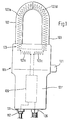
- eine Ansicht des Ausführungsbeispiels,
- Fig. 2
- einen Längsschnitt des Ausführungsbeispiels.
- Fig. 3
- eine perspektivisch dargestellte Ansicht des Ausführungsbeispiels, wobei der Bügel mit ausgezogenen Linien im geöffneten Zustand und mit strichpunktierten Linien im geschlossenen Zustand wiedergegeben ist.
- Fig. 1
- 2 shows a view of the exemplary embodiment,
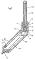
- Fig. 2
- a longitudinal section of the embodiment.
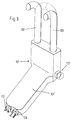
- Fig. 3
- a perspective view of the embodiment, wherein the bracket is shown with solid lines in the open state and with dash-dotted lines in the closed state.
Das in den Fig. 1 bis 3 dargestellte Ausführungsbeispiel des erfindungsgemäßen Gerätes weist ein Gerätegehäuse 101 aus Kunststoff auf, das insofern von einer Quaderform abweicht, als der als Griff dienende Teil 101′ eine geringere Breite hat als der übrige Teil, der außerdem im Ausführungsbeispiel gegenüber dem Griffteil 101′ abgewinkelt ist. Diese Abwinklung ermöglicht es, den Griffteil 101′ in eine Lage etwa parallel zu dem zu messenden Leiter zu bringen, was beispielsweise bei einer Messung in einem Kabelverteilerschrank sehr vorteilhaft ist. Über die dem Griffteil 101′ abgewandte Stirnseite des breiteren Teils des Gerätegehäuses 101 stehen zwei formstabile Spulengehäuse 102 und 103 über, die je einen geradlinigen Abschnitt und einen sich an diesen anschließenden gekrümmten Abschnitt in Form eines Viertelkreises aufweisen. Die beiden geradlinigen Abschnitte sind parallel zueinander so angeordnet, daß zwischen den freien Endflächen ihrer gekrümmten Abschnitte kein Luftspalt oder allenfalls ein geringer Luftspalt vorhanden ist, wenn diese gekrümmten Abschnitte gegeneinander weisen und zusammen mit den geradlinigen Abschnitten einen U-förmigen Bügel mit halbkreisförmigem Jochabschnitt bilden. Die beiden gleich ausgebildeten Spulengehäuse 102 und 103 sind ebenso wie das Gerätegehäuse 101 je aus zwei aus Kunststoff bestehenden Halbschalen zusammengesetzt.The embodiment of the device according to the invention shown in FIGS. 1 to 3 has a
Wie Fig. 2 zeigt, sind die im Inneren des Gerätegehäuses 101 liegenden Endabschnitte der beiden Spulengehäuse 102 und 103 um ihre Längsachse drehbar, aber in axialer Richtung unverschiebbar, im Gerätegehäuse 101 gelagert. Je ein 0-Ring 113 sorgt für eine Dichtung zwischen dem Spulengehäuse und dem Gerätegehäuse 101. Je eine vorgespannte Feder 114, welche jedes Spulengehäuse 102 und 103 in dessen im Gerätegehäuse 101 gelagerten Endabschnitt umgibt, ist einerseits am Gerätegehäuse 101 und andererseits an einem radialen Vorsprung 115 des Spulengehäuses abgestützt. Diese vorgespannten Federn 114 suchen beide Spulengehäuse 102 und 103 in der in Fig. 1 dargestellten Drehlage zu halten, in welcher der U-förmige Bügel geschlossen ist. In dieser Drehlage findet ein zusätzlicher Vorsprung 116 Anschlag an einer Materialpartie des Gerätegehäuses 101.As shown in FIG. 2, the end sections of the two
Das im Gerätegehäuse 101 liegende Ende jedes der beiden Spulengehäuse 102 und 103 trägt eine Scheibe 117 mit einem radialen Schlitz 118, in den ein Zapfen 119 eingreift. In derjenigen Drehlage, in welcher der Bügel geschlossen ist, erstrecken die beiden radialen Schlitze 118 in entgegengesetzte Richtungen. Die beiden Zapfen 119 stehen von einem im Gerätegehäuse 101 in Querrichtung verschiebbar gelagerten Schieber 120 ab, der an seinem einen Ende einen aus dem Gerätegehäuse 101 seitlich im Bereich des breiteren Abschnittes herausragenden Druckknopf 121 bildet. Wenn dieser Druckknopf 121 entgegen der Kraft der Federn 114 in das Gerätegehäuse 101 hineingedrückt wird, wird die translatorische Bewegung des Schiebers 120 in zwei gegensinnige Drehbewegungen der beiden Spulengehäuse 102 und 103 umgesetzt, wodurch diese in die in Fig. 3 mit ausgezogenen Linien dargestellte Lage gedreht werden, in der ihre beiden viertelkreisförmigen Abschnitte in zu einander parallelen Ebenen liegen. In dieser Stellung kann bequem ein elektrischer Leiter eingeführt werden. Wird dann der Druckknopf 121 wieder freigegeben, dann drehen die Feder 114 die beiden Spulengehäuse 102 und 103 wieder in ihre Ausgangslage, die in Fig. 3 mit strichpunktierten Linien dargestellt ist.The end of each of the two
Jedes Spulengehäuse 102 und 103 enthält einen Spulenträger aus Kunststoff, auf den ein erster Abschnitt 123a bzw. ein zweiter Abschnitt 123d derart einlagig gewickelt ist, daß die aktive Fläche jeder Windung gleich ist und die Steigung der Windungen zumindest nahezu konstant ist. Die beiden gleich ausgebildeten Abschnitt 123a und 123d sind Teile einer Luftspule 123, die mehr als 400 Windungen aufweist. Wie Fig. 1 zeigt, verläuft von der der freien Stirnfläche des Spulengehäuse benachbarten Windung sowohl des ersten Abschnitts 123a als auch des zweiten Abschnitts 123d der Luftspule 123 eine Verbindungsleitung zurück in das Gerätegehäuse 101 hinein, wo diese beiden Verbindungsleitungen miteinander verbunden sind. Dadurch bildet der zweite Abschnitt 123d bei geschlossenem Bügel eine Fortsetzung des Abschnittes 123a der Luftspule 123 und umgekehrt. Im Gerätegehäuse 101 liegt, auf einem U-förmigen Spulenträger 124 angeordnet, ein dritter Abschnitt 123c der Luftspule 123, der, wie Fig. 1 zeigt, die im Gerätegehäuse 101 liegenden Enden der Abschnitte 123a und 123d zu einer Ringspule schließt. Außerdem führen von diesem dritten Abschnitt 123c zwei Verbindungsleitungen zu einer im Griffteil 101′ auf einer Trägerplatte angeordneten Signalverarbeitungselektronik 109. Diese beiden Verbindungsleitungen sind an den Anfang bzw. das Ende der Luftspule 123 angeschlossen und führen deshalb der Signalverarbeitungselektronik 109 die in der Luftspule 123 induzierte Spannung zu, die ein Maß für die Stromstärke des von der Luftspule 123 umschlungenen Leiters ist.Each
Selbstverständlich wäre es auch möglich, den dritten Abschnitt 123c der Luftspule 123 im wesentlichen geradlinig auszubilden und, wie in Fig. 1 schematisch dargestellt, zwischen den Enden der beiden Spulengehäuse 102 und 103 anzuordnen.Of course, it would also be possible to design the
Zum Zwecke der Weiterleitung der von der Signalverarbeitungselektronik 109 erzeugten Ausgangssignale und der Energiezufuhr zu der Signalverarbeitungselektronik 109, falls das Gerät keine Batterie enthält, ist an der den Spulengehäusen 102 und 103 abgewandten Stirnseite des Gerätegehäuses 101 für ein Verbindungskabel eine Kabeldurchführung 126 vorgesehen. Neben dieser ist eine Sicherheitssteckbuchse 111 angeordnet zur Aufnahme eines Sicherheitssteckers 112, der am einen Ende eines Labormeßkabels 108 angeordnet ist, dessen anderes Ende an eine vollisolierte, als Spannungsabgriff dienende Klemme angeschlossen ist.For the purpose of forwarding the output signals generated by the
Die Signalverarbeitungselektronik 109 liefert, wenn diese Klemme die Spannung des von der Luftspule 123 umfaßten Leiters führt, außer dem Strommeßwert auch den Spannungsmeßwert und die Wirkleistungen in Form von eingeprägten Strömen. Die Meßbereiche liegen wie beim ersten Ausführungsbeispiel für die Spannung im Bereich bis zu 300 Volt, für die Strommessung im Bereich bis zu 630 Ampere und die Wirkleistung im Bereich bis zu 157 kW.The
Alle in der vorstehenden Beschreibung erwähnten sowie auch die nur allein aus der Zeichnung entnehmbaren Merkmale sind als weitere Ausgestaltungen Bestandteile der Erfindung, auch wenn sie nicht besonders hervorgehoben und insbesondere in den Ansprüchen erwähnt sind.All of the features mentioned in the above description and also the features that can only be inferred from the drawing are components of the invention as further configurations, even if they are not particularly emphasized and are particularly mentioned in the claims.
Claims (10)
- Equipment for measuring current, preferably current and voltage, in conductors of a single or multi-phase system, particularly conductors of low-voltage energy-supply systems, witha) an equipment housing (101),b) an air-core coil (123) of the current sensor, disposed outside the housing (101) for at least part of its length, by means of which the periphery of the conductor can be surrounded and a closed toroidal coil containing the conductor can be formed, the air-core coil (123) havingb1) a first portion (123a) projecting from the equipment housing (101) and having an unchanging hook-like shape open towards the equipment housing (101), andb2) a second portion (123d), also with an unchanging shape, guided for moving in a guide of the equipment housing (101) between a position in which its free end is adjacent that of the first portion (123a) and a position in which the hook formed by the first portion (123a) is open,c) signal-processing electronics (109) which are housed in the equipment housing (101) and to which the signal produced by the current sensor is supplied,
characterized in thatd) when the second portion (123d) is in the position in which its free end is adjacent that of the first portion (123a), it complements the latter to form a U-shaped hoop with sides connected to the equipment housing (101),e) a third portion (123c) of the air-core coil (123), which is free of ferromagnetic material, is provided inside the equipment housing (101) and is connected to the first portion (123a) of the air-core coil (123) on one side and to the second portion (123d) on the other side,f) of two housings (102, 103) containing the first and second portions (123a, 123d) of the air-core coil (123), respectively, at least one is mounted in the equipment housing (101) for rotating about the longitudinal axis of the side of the U-shaped hoop formed thereby. - Equipment according to Claim 1, characterized in that both housings (102, 103) are similarly constructed and each forms one half of the U-shaped hoop.
- Equipment according to Claim 1 or Claim 2, characterized in that the housings (102, 103) containing the first and second portions (123a, 123d) of the aircore coil (123) are of dimensionally stable construction.
- Equipment according to any one of Claims 1 to 3, characterized by a manually-operable operating member (121) disposed outside the equipment housing (101) for a device for moving the second (123d) and, if applicable, also the movable first portion (123a) of the air-core coil (123).
- Equipment according to any one of Claims 1 to 4, characterized by at least one prestressed return spring (114) which seeks to keep the second portion (123d) and, if applicable, also the movable first portion (123a) of the air-core coil in one end position.
- Equipment according to any one of Claims 1 to 5, characterized in that the voltage sensor comprises a clip which is connected or connectible to an instrument lead led out of the equipment housing (101).
- Equipment according to Claim 6, characterized in that the clip is fully insulated, the instrument lead is an insulated, flexible cable, and in order to connect the instrument lead to the signal processing electronics (109), the equipment housing (101) is provided with a laboratory safety socket (111) for housing a safety plug provided on the instrument lead.
- Equipment according to any one of Claims 1 to 7, characterized in that the signal processing electronics (109) have, in addition to their current and voltage outputs, an output for the power defined by current and voltage, particularly the effective power.
- Equipment according to Claim 8, characterized in that the outputs of the signal processing electronics (109) are outputs for load-independent direct currents.
- Equipment according to any one of Claims 1 to 9, characterized in that the equipment housing (101) comprises two portions disposed at an obtuse angle to one another, of which one forms the grip portion (101′) and the other carries the first and second portions (123a, 123d) of the air-core coil (123).
Applications Claiming Priority (2)
| Application Number | Priority Date | Filing Date | Title |
|---|---|---|---|
| DE9014565U | 1990-10-20 | ||
| DE9014565U DE9014565U1 (en) | 1990-10-20 | 1990-10-20 | Device for measuring current and voltage on conductors of a single or multi-phase system |
Publications (2)
| Publication Number | Publication Date |
|---|---|
| EP0482425A1 EP0482425A1 (en) | 1992-04-29 |
| EP0482425B1 true EP0482425B1 (en) | 1995-09-13 |
Family
ID=6858583
Family Applications (1)
| Application Number | Title | Priority Date | Filing Date |
|---|---|---|---|
| EP91117196A Expired - Lifetime EP0482425B1 (en) | 1990-10-20 | 1991-10-09 | Device for measuring current, especially current and voltage, on conductors of a single or multiphase system |
Country Status (6)
| Country | Link |
|---|---|
| EP (1) | EP0482425B1 (en) |
| AT (1) | ATE127930T1 (en) |
| DE (2) | DE9014565U1 (en) |
| DK (1) | DK0482425T3 (en) |
| ES (1) | ES2078410T3 (en) |
| GR (1) | GR3017501T3 (en) |
Families Citing this family (3)
| Publication number | Priority date | Publication date | Assignee | Title |
|---|---|---|---|---|
| EP0607465A1 (en) * | 1992-09-11 | 1994-07-27 | Societe Marechaux Dubost Instruments S.A. | Clip-on current probe with improved operating means |
| FR2717582B1 (en) * | 1994-03-21 | 1996-06-14 | Electricite De France | Device for measuring a voltage drop on a live conductor. |
| FR2973881B1 (en) * | 2011-04-11 | 2013-11-08 | Schneider Electric Ind Sas | DEVICE AND ASSEMBLY FOR MEASURING AN ELECTRICAL CURRENT |
Family Cites Families (9)
| Publication number | Priority date | Publication date | Assignee | Title |
|---|---|---|---|---|
| US3482163A (en) * | 1967-05-24 | 1969-12-02 | Tektronix Inc | Magnetic signal measuring device including degaussing means |
| DE1905468A1 (en) * | 1969-01-31 | 1970-09-10 | Licentia Gmbh | Clamp meter |
| FR2044648A1 (en) * | 1969-05-12 | 1971-02-26 | Arnoux Andre | |
| FR2170303A5 (en) * | 1971-12-07 | 1973-09-14 | Marechaux Dubost & Cie | |
| DE2249278A1 (en) * | 1972-10-07 | 1974-04-18 | Heinrich Dipl Ing List | PROBE FOR DC CLAMP FEEDER |
| FR2538556B1 (en) * | 1982-12-22 | 1985-06-28 | Universal Technic | ELECTRIC CURRENT MEASURING CLIP WITH MAGNETIC CIRCUIT OPENING BY LINEAR MOTION |
| FR2538555B1 (en) * | 1982-12-22 | 1985-08-16 | Universal Technic | ELECTRIC CURRENT MEASURING CLIP WITH MAGNETIC CIRCUIT WITH PIVOTING BRANCH |
| US4806855A (en) * | 1984-06-22 | 1989-02-21 | Davis Murray W | System for rating electric power transmission lines and equipment |
| FR2599848B1 (en) * | 1986-06-10 | 1988-11-25 | Universal Technic | CURRENT MEASURING DEVICE, AND AMPERMETRIC CLAMP COMPRISING SAME |
-
1990
- 1990-10-20 DE DE9014565U patent/DE9014565U1/en not_active Expired - Lifetime
-
1991
- 1991-10-09 EP EP91117196A patent/EP0482425B1/en not_active Expired - Lifetime
- 1991-10-09 AT AT91117196T patent/ATE127930T1/en not_active IP Right Cessation
- 1991-10-09 ES ES91117196T patent/ES2078410T3/en not_active Expired - Lifetime
- 1991-10-09 DK DK91117196.5T patent/DK0482425T3/en active
- 1991-10-09 DE DE59106469T patent/DE59106469D1/en not_active Expired - Fee Related
-
1995
- 1995-09-21 GR GR950402618T patent/GR3017501T3/en unknown
Also Published As
| Publication number | Publication date |
|---|---|
| ES2078410T3 (en) | 1995-12-16 |
| EP0482425A1 (en) | 1992-04-29 |
| GR3017501T3 (en) | 1995-12-31 |
| DK0482425T3 (en) | 1996-01-15 |
| DE9014565U1 (en) | 1991-02-07 |
| ATE127930T1 (en) | 1995-09-15 |
| DE59106469D1 (en) | 1995-10-19 |
Similar Documents
| Publication | Publication Date | Title |
|---|---|---|
| DE1911315C3 (en) | Electric power distribution system | |
| EP0815455B1 (en) | Active optical current measuring system | |
| DE102009026742A1 (en) | Current transformer unit | |
| DE2003076C3 (en) | Metal-enclosed switchgear panel for high voltage | |
| DE2909060B2 (en) | Insulated cable connector | |
| DE3783550T2 (en) | COAXIAL CABLE CONNECTOR. | |
| DE19712900A1 (en) | Sensor system for measuring electric current and voltage esp. for medium voltage | |
| DE4331265A1 (en) | Current transformer for cables | |
| DE3503429C2 (en) | ||
| EP0482425B1 (en) | Device for measuring current, especially current and voltage, on conductors of a single or multiphase system | |
| DE4119830A1 (en) | COMPACT SWITCH WITH DIFFERENT RATED CURRENTS | |
| AT398134B (en) | MEASURING CONVERTER | |
| DE69402610T2 (en) | Superconducting switch and application as supply for a superconducting coil | |
| EP2883234A1 (en) | Current transformer having a short-circuit device | |
| DE3908350A1 (en) | Electrical coil | |
| DE19913017A1 (en) | Monitoring device for measured value in electrical AC circuit in low voltage distribution unit has second voltage tapping located on live core of neighbor phase or neutral conductor for connection to measuring instrument | |
| DE3513474C2 (en) | Drawbars | |
| DE3235421C2 (en) | ||
| DE19802175C2 (en) | Transformation device | |
| DE3029031A1 (en) | APPARATUS FOR REDUCING ELECTRICAL INTERFERENCE VOLTAGES IN ELECTRICAL LINES | |
| DE4121764A1 (en) | Cable connector for coupling to HV measurement and test appts. - has externally accessible connector for each phase and earthing arrangement effective during insertion | |
| DE3884422T2 (en) | Electromagnetic contactor with a lightweight current transformer for a large current range made of sintered metal powder core. | |
| DE1281516B (en) | Tester for batteries from electrical elements | |
| EP0176995A2 (en) | Connecting device for the cable of a measuring or testing apparatus | |
| DE976708C (en) | Low-voltage current transformer for installation in switchgear |
Legal Events
| Date | Code | Title | Description |
|---|---|---|---|
| PUAI | Public reference made under article 153(3) epc to a published international application that has entered the european phase |
Free format text: ORIGINAL CODE: 0009012 |
|
| AK | Designated contracting states |
Kind code of ref document: A1 Designated state(s): AT BE CH DE DK ES FR GB GR IT LI LU NL SE |
|
| 17P | Request for examination filed |
Effective date: 19921015 |
|
| 17Q | First examination report despatched |
Effective date: 19940817 |
|
| GRAA | (expected) grant |
Free format text: ORIGINAL CODE: 0009210 |
|
| AK | Designated contracting states |
Kind code of ref document: B1 Designated state(s): AT BE CH DE DK ES FR GB GR IT LI LU NL SE |
|
| REF | Corresponds to: |
Ref document number: 127930 Country of ref document: AT Date of ref document: 19950915 Kind code of ref document: T |
|
| REF | Corresponds to: |
Ref document number: 59106469 Country of ref document: DE Date of ref document: 19951019 |
|
| REG | Reference to a national code |
Ref country code: GR Ref legal event code: FG4A Free format text: 3017501 |
|
| ET | Fr: translation filed | ||
| ITF | It: translation for a ep patent filed | ||
| REG | Reference to a national code |
Ref country code: ES Ref legal event code: FG2A Ref document number: 2078410 Country of ref document: ES Kind code of ref document: T3 |
|
| GBT | Gb: translation of ep patent filed (gb section 77(6)(a)/1977) |
Effective date: 19951127 |
|
| REG | Reference to a national code |
Ref country code: DK Ref legal event code: T3 |
|
| PLBE | No opposition filed within time limit |
Free format text: ORIGINAL CODE: 0009261 |
|
| STAA | Information on the status of an ep patent application or granted ep patent |
Free format text: STATUS: NO OPPOSITION FILED WITHIN TIME LIMIT |
|
| 26N | No opposition filed | ||
| PGFP | Annual fee paid to national office [announced via postgrant information from national office to epo] |
Ref country code: LU Payment date: 19961001 Year of fee payment: 6 |
|
| PGFP | Annual fee paid to national office [announced via postgrant information from national office to epo] |
Ref country code: SE Payment date: 19961021 Year of fee payment: 6 |
|
| PGFP | Annual fee paid to national office [announced via postgrant information from national office to epo] |
Ref country code: GB Payment date: 19961022 Year of fee payment: 6 Ref country code: DE Payment date: 19961022 Year of fee payment: 6 |
|
| PGFP | Annual fee paid to national office [announced via postgrant information from national office to epo] |
Ref country code: GR Payment date: 19961023 Year of fee payment: 6 Ref country code: ES Payment date: 19961023 Year of fee payment: 6 |
|
| PGFP | Annual fee paid to national office [announced via postgrant information from national office to epo] |
Ref country code: DK Payment date: 19961024 Year of fee payment: 6 Ref country code: AT Payment date: 19961024 Year of fee payment: 6 |
|
| PGFP | Annual fee paid to national office [announced via postgrant information from national office to epo] |
Ref country code: FR Payment date: 19961025 Year of fee payment: 6 |
|
| PGFP | Annual fee paid to national office [announced via postgrant information from national office to epo] |
Ref country code: CH Payment date: 19961028 Year of fee payment: 6 |
|
| PGFP | Annual fee paid to national office [announced via postgrant information from national office to epo] |
Ref country code: NL Payment date: 19961031 Year of fee payment: 6 |
|
| PGFP | Annual fee paid to national office [announced via postgrant information from national office to epo] |
Ref country code: BE Payment date: 19961118 Year of fee payment: 6 |
|
| PG25 | Lapsed in a contracting state [announced via postgrant information from national office to epo] |
Ref country code: LU Free format text: LAPSE BECAUSE OF NON-PAYMENT OF DUE FEES Effective date: 19971009 Ref country code: GB Free format text: LAPSE BECAUSE OF NON-PAYMENT OF DUE FEES Effective date: 19971009 Ref country code: AT Free format text: LAPSE BECAUSE OF NON-PAYMENT OF DUE FEES Effective date: 19971009 |
|
| REG | Reference to a national code |
Ref country code: DK Ref legal event code: EBP |
|
| PG25 | Lapsed in a contracting state [announced via postgrant information from national office to epo] |
Ref country code: SE Free format text: LAPSE BECAUSE OF NON-PAYMENT OF DUE FEES Effective date: 19971010 Ref country code: ES Free format text: LAPSE BECAUSE OF THE APPLICANT RENOUNCES Effective date: 19971010 |
|
| PG25 | Lapsed in a contracting state [announced via postgrant information from national office to epo] |
Ref country code: LI Free format text: LAPSE BECAUSE OF NON-PAYMENT OF DUE FEES Effective date: 19971031 Ref country code: GR Free format text: LAPSE BECAUSE OF NON-PAYMENT OF DUE FEES Effective date: 19971031 Ref country code: FR Free format text: THE PATENT HAS BEEN ANNULLED BY A DECISION OF A NATIONAL AUTHORITY Effective date: 19971031 Ref country code: DK Free format text: LAPSE BECAUSE OF NON-PAYMENT OF DUE FEES Effective date: 19971031 Ref country code: CH Free format text: LAPSE BECAUSE OF NON-PAYMENT OF DUE FEES Effective date: 19971031 Ref country code: BE Free format text: LAPSE BECAUSE OF NON-PAYMENT OF DUE FEES Effective date: 19971031 |
|
| BERE | Be: lapsed |
Owner name: KARL PFISTERER ELEKTROTECHNISCHE SPEZIALARTIKEL G Effective date: 19971031 |
|
| PG25 | Lapsed in a contracting state [announced via postgrant information from national office to epo] |
Ref country code: NL Free format text: LAPSE BECAUSE OF NON-PAYMENT OF DUE FEES Effective date: 19980501 |
|
| GBPC | Gb: european patent ceased through non-payment of renewal fee |
Effective date: 19971009 |
|
| REG | Reference to a national code |
Ref country code: CH Ref legal event code: PL |
|
| NLV4 | Nl: lapsed or anulled due to non-payment of the annual fee |
Effective date: 19980501 |
|
| PG25 | Lapsed in a contracting state [announced via postgrant information from national office to epo] |
Ref country code: DE Free format text: LAPSE BECAUSE OF NON-PAYMENT OF DUE FEES Effective date: 19980701 |
|
| EUG | Se: european patent has lapsed |
Ref document number: 91117196.5 |
|
| REG | Reference to a national code |
Ref country code: FR Ref legal event code: ST |
|
| REG | Reference to a national code |
Ref country code: ES Ref legal event code: FD2A Effective date: 20001102 |
|
| PG25 | Lapsed in a contracting state [announced via postgrant information from national office to epo] |
Ref country code: IT Free format text: LAPSE BECAUSE OF NON-PAYMENT OF DUE FEES;WARNING: LAPSES OF ITALIAN PATENTS WITH EFFECTIVE DATE BEFORE 2007 MAY HAVE OCCURRED AT ANY TIME BEFORE 2007. THE CORRECT EFFECTIVE DATE MAY BE DIFFERENT FROM THE ONE RECORDED. Effective date: 20051009 |