EP0482425B1 - Dispositif pour mesurer le courant, particulièrement de courant et la tension, d'un système de conducteurs à phase singulière ou multiple - Google Patents
Dispositif pour mesurer le courant, particulièrement de courant et la tension, d'un système de conducteurs à phase singulière ou multiple Download PDFInfo
- Publication number
- EP0482425B1 EP0482425B1 EP91117196A EP91117196A EP0482425B1 EP 0482425 B1 EP0482425 B1 EP 0482425B1 EP 91117196 A EP91117196 A EP 91117196A EP 91117196 A EP91117196 A EP 91117196A EP 0482425 B1 EP0482425 B1 EP 0482425B1
- Authority
- EP
- European Patent Office
- Prior art keywords
- air
- housing
- equipment
- section
- voltage
- Prior art date
- Legal status (The legal status is an assumption and is not a legal conclusion. Google has not performed a legal analysis and makes no representation as to the accuracy of the status listed.)
- Expired - Lifetime
Links
Images
Classifications
-
- G—PHYSICS
- G01—MEASURING; TESTING
- G01R—MEASURING ELECTRIC VARIABLES; MEASURING MAGNETIC VARIABLES
- G01R1/00—Details of instruments or arrangements of the types included in groups G01R5/00 - G01R13/00 and G01R31/00
- G01R1/20—Modifications of basic electric elements for use in electric measuring instruments; Structural combinations of such elements with such instruments
- G01R1/22—Tong testers acting as secondary windings of current transformers
Definitions
- the invention relates to a device for measuring current, preferably current and voltage, on conductors of a single-phase or multiphase system, in particular conductors of low-voltage power supply systems, which device has the features of the preamble of claim 1.
- the housing has a U-like shape. In each of the free end faces of the two legs of the device housing, a straight channel for receiving one of the two legs of a U-shaped air coil opens.
- the device housing together with this air coil comprises the busbar, the voltage and current flow of which are to be measured.
- a bridge made of magnetically conductive metal arranged in the yoke part of the device housing connects the two ends of the air coil.
- An electrode arranged in the device housing is capacitively coupled to the busbar when the device housing is placed on the busbar and serves as a voltage sensor.
- Such a device can also be used to measure current and voltage on conductors other than busbars, in particular also on cables. Both the Handling as well as the achievable measuring accuracy are not always satisfactory.
- the first part of the air coil is arranged on a dimensionally stable winding support, which has a C-like shape with a straight yoke section and straight, shorter legs compared to the yoke section, of which one is firmly connected to the device housing.
- the second part of the air coil is carried by a dimensionally stable winding support, which consists of a rectilinear rod, which is pivotally connected to the device housing in the region of its one end in such a way that it rests in one position on the ends of the legs of the first winding support and this supplemented to a closed rectangle, and in its other pivot position keeps the hook formed by the other winding support open.
- the invention is therefore based on the object of providing a device of the type mentioned which is easier to handle than the known devices when used and therefore opens up a wide range of possible uses and also because of a high measuring accuracy. This object is achieved by a device having the features of claim 1.
- the device according to the invention can be used on conductors of any design , for example also conveniently attach to a cable and also remove it from this conductor again.
- conductors of any design for example also conveniently attach to a cable and also remove it from this conductor again.
- part of the air coil that is movable relative to the device housing needs to be brought into a position from the position in which it adjoins the first section and the hook formed by the latter is supplemented to form a U-shaped bracket which the hook for inserting the conductor is open.
- the device can also be designed such that the hook formed by the first section of the air coil is normally open and that it is only supplemented by the second section to form the U-shaped bracket during the measurement.
- the simple handling of the device according to the invention even makes it possible to handle the device with only one hand. It is therefore particularly suitable for measurements on cables and busbars in low-voltage distribution systems, e.g. cable distribution cabinets, house connection boxes and power distribution systems, but also on equipment such as transformers, motors or generators. Because only the insulated device housing is touched by hand for handling, the device can be attached to and removed from the conductor to be measured while it is live.
- the air coil is not closed by a bridge made of magnetically conductive material, i.e. ferromagnetic material, but rather by bringing the ends of its sections into a position in which they connect to one another, the desired measurement accuracy is obtained for the current measurement, specifically regardless of the position of the coil relative to the conductor, since the air coil is one or two layers, the active area of each turn is the same, the pitch of the turns is at least almost constant and the number of turns is more than 400.
- An electrode which is capacitively coupled to the conductor, can be provided in the device housing as a voltage sensor.
- a terminal that can be attached to the conductor is provided, which is connected via a flexible cable to the signal processing electronics contained in the device housing.
- the two housings containing the first and second sections of the air coil are preferably of identical design, so that they each form one half of the U-shaped bracket.
- the air coil adapts very well to a cable.
- a manually operable drive element is provided outside the device housing. that can have the shape of a push button or slide, for example.
- manual drive is preferably provided at least one preloaded spring which tries to keep the movable section or sections in one of the two end positions. For example, if the spring holds the movable section or sections in the position resulting in a closed bracket, then the drive member need only be moved against the force of the return spring to open the bracket.
- the signal processing electronics preferably have an output for a signal which represents the power, preferably the active power.
- the signal processing electronics deliver the output signals in the form of impressed currents.
- the measured values could also be output in digital form.
- the output signals supplied by the signal processing electronics can be fed via a connecting line to a device which displays and / or prints out the measured values.
- a device which displays and / or prints out the measured values.
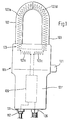
- the embodiment of the device according to the invention shown in FIGS. 1 to 3 has a device housing 101 made of plastic, which differs from a cuboid shape in that the part serving as a handle 101 'has a smaller width than the rest of the part, which is also opposite in the embodiment the handle part 101 'is angled. This bend enables the handle part 101 'to be brought into a position approximately parallel to the conductor to be measured, which is very advantageous, for example, when measuring in a cable distribution cabinet.
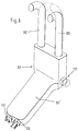
- About the handle portion 101 'facing away from the wider part of the device housing 101 are two dimensionally stable coil housings 102 and 103, each having a straight section and an adjoining curved section in the form of a quarter circle.
- the two rectilinear sections are arranged parallel to one another in such a way that there is no air gap or at most a small air gap between the free end faces of their curved sections if these curved sections point towards one another and together with the rectilinear sections form a U-shaped bracket with a semicircular yoke section.
- the two identical coil housings 102 and 103 like the device housing 101, are each composed of two half shells made of plastic.
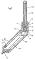
- the end sections of the two coil housings 102 and 103 that are located inside the device housing 101 are mounted in the device housing 101 so that they can rotate about their longitudinal axis, but are not displaceable in the axial direction.
- One O-ring 113 provides a seal between the coil housing and the device housing 101.
- One preloaded spring 114 which surrounds each coil housing 102 and 103 in its end section mounted in the device housing 101, is on the one hand on the device housing 101 and on the other hand supported on a radial projection 115 of the coil housing. These pretensioned springs 114 try to hold both coil housings 102 and 103 in the rotational position shown in FIG. 1, in which the U-shaped bracket is closed. In this rotational position, an additional projection 116 stops on a material section of the device housing 101.
- each of the two coil housings 102 and 103 lying in the device housing 101 carries a disk 117 with a radial slot 118 into which a pin 119 engages.
- the two radial slots 118 extend in opposite directions.
- the two pins 119 protrude from a slide 120 which is mounted in the device housing 101 so as to be displaceable in the transverse direction and which at one end forms a push button 121 which projects laterally from the device housing 101 in the region of the wider section.
- Each bobbin case 102 and 103 contains a plastic bobbin on which a first section 123a and a second section 123d are wound in one layer such that the active area of each turn is the same and the pitch the turns are at least almost constant.
- the two identical sections 123a and 123d are parts of an air coil 123 which has more than 400 turns.
- a connecting line runs from the turn adjacent to the free end face of the coil housing of both the first section 123a and the second section 123d of the air coil 123 back into the device housing 101, where these two connecting lines are connected to one another.
- the bracket is closed, the second section 123d forms a continuation of the section 123a of the air coil 123 and vice versa.
- a third section 123c of the air coil 123 which, as shown in FIG. 1, closes the ends of the sections 123a and 123d in the device housing 101 to form a ring coil.
- two connecting lines lead to signal processing electronics 109 arranged in the handle part 101 'on a carrier plate. These two connecting lines are connected to the beginning or end of the air coil 123 and therefore lead the signal processing electronics 109 to the voltage induced in the air coil 123 to, which is a measure of the current intensity of the conductor wrapped in the air coil 123.
- a cable bushing 126 is provided on the end face of the device housing 101 facing away from the coil housings 102 and 103 for a connecting cable.
- a safety socket 111 is arranged for receiving a safety plug 112 is arranged at one end of a laboratory measuring cable 108, the other end of which is connected to a fully insulated terminal serving as a voltage tap.
- the signal processing electronics 109 when this terminal carries the voltage of the conductor enclosed by the air coil 123, in addition to the current measured value, also the voltage measured value and the active powers in the form of impressed currents.
- the measuring ranges are for the voltage in the range up to 300 volts, for current measurement in the range up to 630 amperes and the active power in the range up to 157 kW.
Landscapes
- Engineering & Computer Science (AREA)
- Power Engineering (AREA)
- Physics & Mathematics (AREA)
- General Physics & Mathematics (AREA)
- Measuring Instrument Details And Bridges, And Automatic Balancing Devices (AREA)
- Measurement Of Current Or Voltage (AREA)
- Electrical Discharge Machining, Electrochemical Machining, And Combined Machining (AREA)
- Transformers For Measuring Instruments (AREA)
- General Induction Heating (AREA)
Claims (10)
- Appareil de mesure de courant, avantageusement de courant et de tension, dans des conducteurs d'un système monophasé ou polyphasé, notamment des conducteurs d'installations d'alimentation en énergie basse tension, comportanta) un carter d'appareil (101),b) une bobine sans fer (123) du détecteur de courant située au moins sur une partie de sa longueur à l'extérieur du carter (101), au moyen de laquelle le conducteur peut être entouré sur son pourtour, et qui peut être réalisée sous la forme d'une bobine annulaire intrinsèquement fermée et contenant le conducteur, cette bobine sans fer (123)b1) comportant une première partie (123a) faisant saillie du carter d'appareil (101) et ayant une forme non modifiable de crochet ouvert en direction du carter d'appareil (101), et égalementb2) une seconde partie (123d) ayant également une forme non modifiable et qui est guidée de façon mobile, dans un guide du carter d'appareil (101), entre une position dans laquelle son extrémité libre est jointe à celle de la première partie (123a), et une position dans laquelle le crochet formé par la première partie (123a) est ouvert,c) un circuit électronique de traitement de signaux (109) logé dans le carter d'appareil 101 et recevant les signaux produits par le détecteur de courant,
caractérisé en ce qued) la seconde partie (123d) produit, dans la position où son extrémité libre est jointe à celle de la première partie (123a), un complément de cette partie par les branches jointes au carter d'appareil (101) pour créer un étrier en forme de U,e) il est prévu à l'intérieur du carter d'appareil (101) une troisième partie (123c) de la bobine sans fer (123), exempte de matériau ferromagnétique et qui est jointe d'une part à la première partie (123a) de la bobine sans fer (123) et d'autre part à la seconde partie (123d),f) au moins l'un des deux carters (102, 103) contenant la première et la seconde partie (123a, 123d) de la bobine sans fer (123), est monté dans le carter d'appareil (101) de façon à pouvoir tourner autour de l'axe longitudinal de la branche, formée par lui, de l'étrier en forme de U. - Appareil selon la revendication 1, caractérisé en ce que les deux carters (102, 103) sont agencés de façon identique et constituent chacun une moitié de l'étrier en forme de U.
- Appareil selon la revendication 1 ou 2, caractérisé en ce que les carters (102, 103) contenant la première et la seconde partie (123a, 123d) de la bobine sans fer(123) sont agencés avec une forme stable.
- Appareil selon une des revendications 1 à 3, caractérisé par un organe d'entraînement, situé à l'extérieur du carter d'appareil (101), pouvant être actionné manuellement et assurant l'entraînement d'un dispositif pour déplacer la seconde partie (123d) de la bobine sans fer (123), et de la première partie (123a), le cas échéant également mobile, de ladite bobine (123).
- Appareil selon une des revendications 1 à 4, caractérisé par un ressort de retenue précontraint (114), qui a tendance à maintenir la seconde partie (123d), et le cas échéant la première partie (123a), également mobile, de la bobine sans fer dans une des positions limites.
- Appareil selon une des revendications 1 à 5, caractérisé en ce que le détecteur de tension comporte une borne, qui est reliée ou qui peut être reliée à un conducteur de mesure sortant du carter d'appareil (101).
- Appareil selon la revendication 6, caractérisé en ce que la borne est complètement isolée, le conducteur de mesure est un câble flexible isolé et, pour une liaison du conducteur de mesure avec le circuit électronique de traitement de signaux (109) , le carter d'appareil (101) est pourvu d'une douille pour fiche de sécurité de laboratoire (111) destinée à recevoir une fiche de sécurité (112) prévue sur le conducteur de mesure.
- Appareil selon une des revendications 1 à 7, caractérisé en ce que le circuit électronique de traitement de signaux (109) comporte, en plus de ses sorties de courant et de tension, une sortie pour la puissance déterminée à partir du courant et de la tension, notamment la puissance active.
- Appareil selon la revendication 8, caractérisé en ce que les sorties du circuit électronique de traitement de signaux (109) sont des sorties pour des courants continus imprimés.
- Appareil selon une des revendications 1 à 9, caractérisé en ce que le carter de l'appareil (101) comporte deux parties orientées d'un angle obtus l'une par rapport à l'autre et dont l'une constitue la partie formant poignée (101′) tandis que l'autre porte la première et la seconde partie (123a, 123b) de la bobine sans fer (123).
Applications Claiming Priority (2)
| Application Number | Priority Date | Filing Date | Title |
|---|---|---|---|
| DE9014565U DE9014565U1 (de) | 1990-10-20 | 1990-10-20 | Gerät zur Messung von Strom und Spannung an Leitern eines ein- oder mehrphasigen Systems |
| DE9014565U | 1990-10-20 |
Publications (2)
| Publication Number | Publication Date |
|---|---|
| EP0482425A1 EP0482425A1 (fr) | 1992-04-29 |
| EP0482425B1 true EP0482425B1 (fr) | 1995-09-13 |
Family
ID=6858583
Family Applications (1)
| Application Number | Title | Priority Date | Filing Date |
|---|---|---|---|
| EP91117196A Expired - Lifetime EP0482425B1 (fr) | 1990-10-20 | 1991-10-09 | Dispositif pour mesurer le courant, particulièrement de courant et la tension, d'un système de conducteurs à phase singulière ou multiple |
Country Status (6)
| Country | Link |
|---|---|
| EP (1) | EP0482425B1 (fr) |
| AT (1) | ATE127930T1 (fr) |
| DE (2) | DE9014565U1 (fr) |
| DK (1) | DK0482425T3 (fr) |
| ES (1) | ES2078410T3 (fr) |
| GR (1) | GR3017501T3 (fr) |
Families Citing this family (3)
| Publication number | Priority date | Publication date | Assignee | Title |
|---|---|---|---|---|
| EP0607465A1 (fr) * | 1992-09-11 | 1994-07-27 | Societe Marechaux Dubost Instruments S.A. | Pince ampèremétrique comprenant des moyens d'actionnement perfectionnés |
| FR2717582B1 (fr) * | 1994-03-21 | 1996-06-14 | Electricite De France | Dispositif de mesure d'une chute de tension sur un conducteur sous tension. |
| FR2973881B1 (fr) | 2011-04-11 | 2013-11-08 | Schneider Electric Ind Sas | Dispositif et ensemble de mesure d'un courant electrique |
Family Cites Families (9)
| Publication number | Priority date | Publication date | Assignee | Title |
|---|---|---|---|---|
| US3482163A (en) * | 1967-05-24 | 1969-12-02 | Tektronix Inc | Magnetic signal measuring device including degaussing means |
| DE1905468A1 (de) * | 1969-01-31 | 1970-09-10 | Licentia Gmbh | Strommesszange |
| FR2044648A1 (fr) * | 1969-05-12 | 1971-02-26 | Arnoux Andre | |
| FR2170303A5 (fr) * | 1971-12-07 | 1973-09-14 | Marechaux Dubost & Cie | |
| DE2249278A1 (de) * | 1972-10-07 | 1974-04-18 | Heinrich Dipl Ing List | Sonde fuer gleichstrom-zangenanleger |
| FR2538556B1 (fr) * | 1982-12-22 | 1985-06-28 | Universal Technic | Pince de mesure de courant electrique a circuit magnetique s'ouvrant par mouvement lineaire |
| FR2538555B1 (fr) * | 1982-12-22 | 1985-08-16 | Universal Technic | Pince de mesure de courant electrique a circuit magnetique a branche pivotante |
| US4806855A (en) * | 1984-06-22 | 1989-02-21 | Davis Murray W | System for rating electric power transmission lines and equipment |
| FR2599848B1 (fr) * | 1986-06-10 | 1988-11-25 | Universal Technic | Dispositif de mesure de courant, et pince amperemetrique le comportant |
-
1990
- 1990-10-20 DE DE9014565U patent/DE9014565U1/de not_active Expired - Lifetime
-
1991
- 1991-10-09 DK DK91117196.5T patent/DK0482425T3/da active
- 1991-10-09 EP EP91117196A patent/EP0482425B1/fr not_active Expired - Lifetime
- 1991-10-09 ES ES91117196T patent/ES2078410T3/es not_active Expired - Lifetime
- 1991-10-09 DE DE59106469T patent/DE59106469D1/de not_active Expired - Fee Related
- 1991-10-09 AT AT91117196T patent/ATE127930T1/de not_active IP Right Cessation
-
1995
- 1995-09-21 GR GR950402618T patent/GR3017501T3/el unknown
Also Published As
| Publication number | Publication date |
|---|---|
| GR3017501T3 (en) | 1995-12-31 |
| ATE127930T1 (de) | 1995-09-15 |
| DK0482425T3 (da) | 1996-01-15 |
| EP0482425A1 (fr) | 1992-04-29 |
| DE59106469D1 (de) | 1995-10-19 |
| ES2078410T3 (es) | 1995-12-16 |
| DE9014565U1 (de) | 1991-02-07 |
Similar Documents
| Publication | Publication Date | Title |
|---|---|---|
| DE1911315C3 (de) | Elektrisches Stromverteilungssystem | |
| EP0815455B1 (fr) | Systeme optique actif de mesure du courant | |
| DE102009026742A1 (de) | Stromwandlereinheit | |
| DE2003076C3 (de) | Metallumschlossenes Schaltfeld für hohe Spannung | |
| DE2909060B2 (de) | Isolierter Kabelstecker | |
| DE3783550T2 (de) | Koaxialkabelverbinder. | |
| DE19712900A1 (de) | Sensoranordnung zur Strom- und Spannungsmessung | |
| DE4331265A1 (de) | Stromwandler für Leitungen | |
| DE3503429C2 (fr) | ||
| EP0482425B1 (fr) | Dispositif pour mesurer le courant, particulièrement de courant et la tension, d'un système de conducteurs à phase singulière ou multiple | |
| DE4119830A1 (de) | Kompakt-schalter mit verschiedenen nennstroemen | |
| AT398134B (de) | Messwandler | |
| EP2883234A1 (fr) | Transformateur de courant comprenant un dispositif de court-circuit | |
| DE69402610T2 (de) | Supraleitender Schalter und Anwendung als Speisung einer supraleitenden Spule | |
| EP0312871A2 (fr) | Adaptateur avec un boîtier pour la connexion de lampes fluorescentes ou à basse tension à des rails | |
| DE3908350A1 (de) | Elektrische spule | |
| DE19913017A1 (de) | Überwachungsgerät in einem Wechselstromkreis | |
| DE3235421C2 (fr) | ||
| DE19802175C2 (de) | Transformationseinrichtung | |
| DE3029031A1 (de) | Apparat zum reduzieren elektrischer stoerspannungen in elektrischen leitungen | |
| DE4121764A1 (de) | Vorrichtung zum verbinden einer kabelmess- und pruefeinrichtung mit an eine gekapselte schaltanlage angeschlossenen kabeln | |
| DE1281516B (de) | Pruefgeraet fuer Batterien aus elektrischen Elementen | |
| EP0176995A2 (fr) | Dispositif de connexion pour un câble d'appareil de mesure ou d'essai | |
| CH717091B1 (de) | Stromzange. | |
| DE976708C (de) | Niederspannungsstromwandler zum Einbau in Schaltanlagen |
Legal Events
| Date | Code | Title | Description |
|---|---|---|---|
| PUAI | Public reference made under article 153(3) epc to a published international application that has entered the european phase |
Free format text: ORIGINAL CODE: 0009012 |
|
| AK | Designated contracting states |
Kind code of ref document: A1 Designated state(s): AT BE CH DE DK ES FR GB GR IT LI LU NL SE |
|
| 17P | Request for examination filed |
Effective date: 19921015 |
|
| 17Q | First examination report despatched |
Effective date: 19940817 |
|
| GRAA | (expected) grant |
Free format text: ORIGINAL CODE: 0009210 |
|
| AK | Designated contracting states |
Kind code of ref document: B1 Designated state(s): AT BE CH DE DK ES FR GB GR IT LI LU NL SE |
|
| REF | Corresponds to: |
Ref document number: 127930 Country of ref document: AT Date of ref document: 19950915 Kind code of ref document: T |
|
| REF | Corresponds to: |
Ref document number: 59106469 Country of ref document: DE Date of ref document: 19951019 |
|
| REG | Reference to a national code |
Ref country code: GR Ref legal event code: FG4A Free format text: 3017501 |
|
| ET | Fr: translation filed | ||
| ITF | It: translation for a ep patent filed | ||
| REG | Reference to a national code |
Ref country code: ES Ref legal event code: FG2A Ref document number: 2078410 Country of ref document: ES Kind code of ref document: T3 |
|
| GBT | Gb: translation of ep patent filed (gb section 77(6)(a)/1977) |
Effective date: 19951127 |
|
| REG | Reference to a national code |
Ref country code: DK Ref legal event code: T3 |
|
| PLBE | No opposition filed within time limit |
Free format text: ORIGINAL CODE: 0009261 |
|
| STAA | Information on the status of an ep patent application or granted ep patent |
Free format text: STATUS: NO OPPOSITION FILED WITHIN TIME LIMIT |
|
| 26N | No opposition filed | ||
| PGFP | Annual fee paid to national office [announced via postgrant information from national office to epo] |
Ref country code: LU Payment date: 19961001 Year of fee payment: 6 |
|
| PGFP | Annual fee paid to national office [announced via postgrant information from national office to epo] |
Ref country code: SE Payment date: 19961021 Year of fee payment: 6 |
|
| PGFP | Annual fee paid to national office [announced via postgrant information from national office to epo] |
Ref country code: GB Payment date: 19961022 Year of fee payment: 6 Ref country code: DE Payment date: 19961022 Year of fee payment: 6 |
|
| PGFP | Annual fee paid to national office [announced via postgrant information from national office to epo] |
Ref country code: GR Payment date: 19961023 Year of fee payment: 6 Ref country code: ES Payment date: 19961023 Year of fee payment: 6 |
|
| PGFP | Annual fee paid to national office [announced via postgrant information from national office to epo] |
Ref country code: DK Payment date: 19961024 Year of fee payment: 6 Ref country code: AT Payment date: 19961024 Year of fee payment: 6 |
|
| PGFP | Annual fee paid to national office [announced via postgrant information from national office to epo] |
Ref country code: FR Payment date: 19961025 Year of fee payment: 6 |
|
| PGFP | Annual fee paid to national office [announced via postgrant information from national office to epo] |
Ref country code: CH Payment date: 19961028 Year of fee payment: 6 |
|
| PGFP | Annual fee paid to national office [announced via postgrant information from national office to epo] |
Ref country code: NL Payment date: 19961031 Year of fee payment: 6 |
|
| PGFP | Annual fee paid to national office [announced via postgrant information from national office to epo] |
Ref country code: BE Payment date: 19961118 Year of fee payment: 6 |
|
| PG25 | Lapsed in a contracting state [announced via postgrant information from national office to epo] |
Ref country code: LU Free format text: LAPSE BECAUSE OF NON-PAYMENT OF DUE FEES Effective date: 19971009 Ref country code: GB Free format text: LAPSE BECAUSE OF NON-PAYMENT OF DUE FEES Effective date: 19971009 Ref country code: AT Free format text: LAPSE BECAUSE OF NON-PAYMENT OF DUE FEES Effective date: 19971009 |
|
| REG | Reference to a national code |
Ref country code: DK Ref legal event code: EBP |
|
| PG25 | Lapsed in a contracting state [announced via postgrant information from national office to epo] |
Ref country code: SE Free format text: LAPSE BECAUSE OF NON-PAYMENT OF DUE FEES Effective date: 19971010 Ref country code: ES Free format text: LAPSE BECAUSE OF THE APPLICANT RENOUNCES Effective date: 19971010 |
|
| PG25 | Lapsed in a contracting state [announced via postgrant information from national office to epo] |
Ref country code: LI Free format text: LAPSE BECAUSE OF NON-PAYMENT OF DUE FEES Effective date: 19971031 Ref country code: GR Free format text: LAPSE BECAUSE OF NON-PAYMENT OF DUE FEES Effective date: 19971031 Ref country code: FR Free format text: THE PATENT HAS BEEN ANNULLED BY A DECISION OF A NATIONAL AUTHORITY Effective date: 19971031 Ref country code: DK Free format text: LAPSE BECAUSE OF NON-PAYMENT OF DUE FEES Effective date: 19971031 Ref country code: CH Free format text: LAPSE BECAUSE OF NON-PAYMENT OF DUE FEES Effective date: 19971031 Ref country code: BE Free format text: LAPSE BECAUSE OF NON-PAYMENT OF DUE FEES Effective date: 19971031 |
|
| BERE | Be: lapsed |
Owner name: KARL PFISTERER ELEKTROTECHNISCHE SPEZIALARTIKEL G Effective date: 19971031 |
|
| PG25 | Lapsed in a contracting state [announced via postgrant information from national office to epo] |
Ref country code: NL Free format text: LAPSE BECAUSE OF NON-PAYMENT OF DUE FEES Effective date: 19980501 |
|
| GBPC | Gb: european patent ceased through non-payment of renewal fee |
Effective date: 19971009 |
|
| REG | Reference to a national code |
Ref country code: CH Ref legal event code: PL |
|
| NLV4 | Nl: lapsed or anulled due to non-payment of the annual fee |
Effective date: 19980501 |
|
| PG25 | Lapsed in a contracting state [announced via postgrant information from national office to epo] |
Ref country code: DE Free format text: LAPSE BECAUSE OF NON-PAYMENT OF DUE FEES Effective date: 19980701 |
|
| EUG | Se: european patent has lapsed |
Ref document number: 91117196.5 |
|
| REG | Reference to a national code |
Ref country code: FR Ref legal event code: ST |
|
| REG | Reference to a national code |
Ref country code: ES Ref legal event code: FD2A Effective date: 20001102 |
|
| PG25 | Lapsed in a contracting state [announced via postgrant information from national office to epo] |
Ref country code: IT Free format text: LAPSE BECAUSE OF NON-PAYMENT OF DUE FEES;WARNING: LAPSES OF ITALIAN PATENTS WITH EFFECTIVE DATE BEFORE 2007 MAY HAVE OCCURRED AT ANY TIME BEFORE 2007. THE CORRECT EFFECTIVE DATE MAY BE DIFFERENT FROM THE ONE RECORDED. Effective date: 20051009 |