EP0482425A1 - Dispositif pour mesurer le courant, particulièrement de courant et la tension, d'un système de conducteurs à phase singulière ou multiple - Google Patents
Dispositif pour mesurer le courant, particulièrement de courant et la tension, d'un système de conducteurs à phase singulière ou multiple Download PDFInfo
- Publication number
- EP0482425A1 EP0482425A1 EP91117196A EP91117196A EP0482425A1 EP 0482425 A1 EP0482425 A1 EP 0482425A1 EP 91117196 A EP91117196 A EP 91117196A EP 91117196 A EP91117196 A EP 91117196A EP 0482425 A1 EP0482425 A1 EP 0482425A1
- Authority
- EP
- European Patent Office
- Prior art keywords
- section
- device housing
- air coil
- voltage
- coil
- Prior art date
- Legal status (The legal status is an assumption and is not a legal conclusion. Google has not performed a legal analysis and makes no representation as to the accuracy of the status listed.)
- Granted
Links
- 239000004020 conductor Substances 0.000 title claims abstract description 29
- 239000003302 ferromagnetic material Substances 0.000 claims abstract description 3
- 239000013589 supplement Substances 0.000 claims 1
- 238000009434 installation Methods 0.000 abstract 1
- 238000005259 measurement Methods 0.000 description 11
- 210000003811 finger Anatomy 0.000 description 3
- 230000004308 accommodation Effects 0.000 description 1
- 238000006073 displacement reaction Methods 0.000 description 1
- 238000003780 insertion Methods 0.000 description 1
- 230000037431 insertion Effects 0.000 description 1
- 239000000463 material Substances 0.000 description 1
- 239000002184 metal Substances 0.000 description 1
- 239000007787 solid Substances 0.000 description 1
- 210000003813 thumb Anatomy 0.000 description 1
Images


Classifications
-
- G—PHYSICS
- G01—MEASURING; TESTING
- G01R—MEASURING ELECTRIC VARIABLES; MEASURING MAGNETIC VARIABLES
- G01R1/00—Details of instruments or arrangements of the types included in groups G01R5/00 - G01R13/00 and G01R31/00
- G01R1/20—Modifications of basic electric elements for use in electric measuring instruments; Structural combinations of such elements with such instruments
- G01R1/22—Tong testers acting as secondary windings of current transformers
Definitions
- the invention relates to a device for measuring current, preferably current and voltage, on conductors of a single-phase or multiphase system, in particular conductors of low-voltage power supply systems, which device has the features of the preamble of claim 1.
- the housing has a U-like shape.
- a straight channel for receiving one of the two legs of a U-shaped air coil opens.
- the device housing together with this air coil includes the busbar, the voltage and current flow of which is to be measured.
- a bridge made of magnetically conductive metal arranged in the yoke part of the device housing connects the two ends of the air coil.
- An electrode arranged in the device housing is capacitively coupled to the busbar when the device housing is placed on the busbar and serves as a voltage sensor.
- Such a device can also be used to measure current and voltage on conductors other than busbars, in particular also on cables. Both the Handling as well as the achievable measuring accuracy are then not always satisfactory.
- the invention is therefore based on the object to improve a device of the type mentioned in such a way that it is easier to handle when used with conductors other than busbars, in particular cables, and in particular a higher measurement accuracy can be achieved.
- This object is achieved by a device having the features of claim 1.
- the device according to the invention can be used on conductors of any design, for example also on a cable, start comfortably and remove from this conductor again.
- the air coil which is movable relative to the device housing needs to be brought temporarily into a position from the position in which it adjoins the first section and the hook formed by the latter is supplemented to form a U-shaped bracket the hook for inserting the conductor is open.
- the device can also be designed such that the hook formed by the first section of the air coil is normally open and that it is only supplemented by the second section to form the U-shaped bracket during the measurement.
- the simple handling of the device according to the invention even makes it possible to handle the device with only one hand. It is therefore particularly suitable for measurements on cables and busbars in low-voltage distribution systems, e.g. cable distribution cabinets, house connection boxes and power distribution systems, but also on equipment such as transformers, motors or generators. Because only the insulated device housing is touched by hand for handling, the device can be attached to and removed from the conductor to be measured under voltage.
- the air coil is not closed by a bridge made of magnetically conductive material, i.e. ferromagnetic material, but rather by bringing the ends of its sections into a position in which they connect to one another, the desired measurement accuracy is obtained for the current measurement, specifically regardless of the position of the coil relative to the conductor, since the air coil is one or two layers, the active area of each turn is the same, the pitch of the turns is at least almost constant and the number of turns is more than 400.
- An electrode which is capacitively coupled to the conductor, can be provided in the device housing as a voltage sensor.
- a terminal that can be attached to the conductor is provided, which is connected via a flexible cable to the signal processing electronics contained in the device housing.
- the first and second sections of the air coil each lie in a dimensionally stable housing.
- the second section of the air coil can have a straight extension and can be displaced out of and into the device housing in the direction of its longitudinal extension, provided that the free end of the first forming the hook Section against the device housing and the free end of the second section of the air coil.
- the section provided in the interior of the device housing, which connects the ends of the first and second sections lying here, can be designed flexibly in order to be able to adapt easily to the changeable positions which the end of the second section of the air coil lying in the device housing can take can.
- the device according to the invention can also be designed such that at least one of the parts of the device having the first or second section of the air coil is rotatably mounted in the device housing about the longitudinal axis of the leg of the U-type bracket formed by it.
- the bracket can then be opened in such a way to accommodate the conductor on which the measurements are to be carried out, that the hooks formed by the two sections, the free ends of which point towards one another when the bracket is closed, are brought into a position in which they are have the necessary distance from each other for the accommodation of the conductor
- the two hook-shaped ends can lie in mutually parallel planes.
- the two parts containing the first or second section of the air coil are preferably of identical design, so that they each form one half of the U-shaped bracket.
- the air coil adapts very well to a cable.
- a manually operable drive member is provided outside the device housing. that can have the shape of a push button or slide, for example.
- manual drive is preferably provided at least one preloaded spring which tries to keep the movable section or sections in one of the two end positions. For example, if the spring holds the movable section or sections in the position resulting in a closed bracket, then the drive member need only be moved against the force of the return spring to open the bracket.
- the signal processing electronics preferably have an output for a signal which represents the power, preferably the active power.
- the signal processing electronics deliver the output signals in the form of impressed currents.
- the measured values could also be output in digital form.
- the output signals supplied by the signal processing electronics can be fed via a connecting line to a device which displays and / or prints out the measured values.
- a device which displays and / or prints out the measured values.
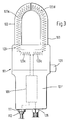
- a device for measuring currents and voltages on conductors of a single or multi-phase system, in particular conductors of low-voltage power supply systems and devices connected to them, as shown in FIG. 1, has an elongated, rectangular device housing 1 made of plastic, which can be comfortably gripped with one hand can. On one end of the device housing 1 there is a sealed insertion for an energy supply cable 10 and next to it a laboratory safety socket 11. A laboratory safety plug 12 is inserted into the latter and is provided at one end of an insulated, flexible laboratory measuring cable 8. The other end of the laboratory measuring cable 8 is provided with a fully insulated clamp 7, which is only shown schematically in FIG. 2.
- the device housing At the other end of the device housing is an L-like, but rounded on the inside extension 2, which is dimensionally stable like the device housing 1.
- the leg of the extension 2 which extends in the longitudinal direction of the device housing 1 forms a dimensionally stable housing for a rectilinear section of an air coil 3, which is usually referred to as a Rogowsky coil the piece 3a forms a hook open towards the device housing 1.
- the semicircularly curved piece 3b is arranged in a dimensionally stable housing made of plastic, which is rigidly connected to the extension 2, so that overall the hook-shaped section of the air coil 3 is dimensionally stable and cannot change its position relative to the device housing 1.
- the straight piece 3a of the air coil 3 extends into the device housing 1.
- a flexible piece 3c which is in the device housing 1 forms a semicircle-like loop.
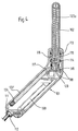
- a linear guide 4 of the device housing 1 which is aligned with the free end of the circularly curved piece 3b of the air coil 3
- a linear, dimensionally stable piece 3d of the air coil 3 is guided in a longitudinally displaceable manner and connects to the flexible piece 3c.
- the straight-line piece 3d In its completely retracted position, which is shown in solid lines in FIG. 2, the straight-line piece 3d does not protrude or only slightly over the leg of the extension 2 extending transversely to the longitudinal extension of the piece 3d. From this position, the straight-line piece 3d can be moved into the position shown in dashed lines in FIG. 2, in which it lies without a gap at the end of the semicircularly curved section 3b and the air coil forms a closed ring body.
- an arcuately curved slot 5 is provided in one side wall of the device housing 1, through which a finger passes, which carries an actuating button 6 arranged on the outside of the device housing 1.
- the slot 5 and the actuating button 6 are designed so that the user, who has gripped the device with one hand, with one finger, for example the thumb, the actuating button 6 from the end of the slot 5 pointing towards the extension 2 towards the other end of the slot 5, ie away from the extension 2.
- the resulting displacement of the finger carrying the actuating button 6 is transmitted directly or indirectly to the rectilinear section 3d of the air coil 3, as a result of which this is pulled back into the position shown in solid lines in FIG. 2.
- this movement of the straight-line piece 3d of the air coil 3 into the device housing 1 takes place against the force of a return spring, not shown.
- the actuation button 6 therefore only needs to be released again after the actuation and attachment of the hook-shaped section of the air coil 3 to a cable or the like in order to make the device ready for measurement to make, because when the actuating button 6 is released, the straight piece 3d of the air coil 3 is brought from the return spring into the position shown in dashed lines in FIG. 2.
- the flexible piece 3c of the air coil 3 changes its position when the dimensionally stable piece 3d is displaced, as is indicated in FIG. 2 by the solid and dashed lines.
- the flexible piece 3c and the straight-line, dimensionally stable piece 3d of the air coil 3 are also embedded in a plastic body serving as a housing.
- the air coil 3 is formed in one layer, has an active area of at least 70 mm2, a number of turns of more than 400 and an at least almost constant pitch for each turn. Because of the large area in which the cable diameters lie, it may be necessary to provide different curvature diameters for the semicircularly curved piece 3b of the air coil 3. In the exemplary embodiment, three different curvature diameters are provided, which are adapted to cables up to 26 mm in diameter, up to 40 mm in diameter and up to 58 mm in diameter.
- terminal 7 is connected for a galvanic connection to the conductor on which the measurement is to be carried out or to a body at the same potential.
- the terminal 7 is connected via the flexible cable 8 to signal processing electronics 9 arranged in the device housing 1.
- the air coil 3 is also connected to this.
- the signal processing electronics 9 delivers the measured values for the voltage, the current and the active power in the form of impressed currents.
- the measuring ranges for the voltage are between 0 and 300 volts, for the current measurement between 0 and 630 amps and for the active power between 0 and 157 kW.
- the energy supply is provided via an interface.
- a battery could also be accommodated in the device housing 1.
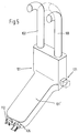
- the second embodiment of the device according to the invention shown in FIGS. 3 to 5 has a device housing 101 made of plastic, which differs from a cuboid shape in that the part 101 'serving as a handle has a smaller width than the rest of the part, which is also in the embodiment is angled relative to the handle part 101 '. This angling enables the handle part 101 'to be brought into a position approximately parallel to the conductor to be measured, which is very advantageous, for example, when measuring in a cable distribution cabinet.
- Two dimensionally stable coil housings 102 and 103 protrude beyond the end face of the wider part of the device housing 101 facing away from the handle part 101 ', each of which has a rectilinear section and an adjoining curved section in the form of a quarter circle.
- the two rectilinear sections are arranged parallel to one another in such a way that there is no air gap or at most a small air gap between the free end faces of their curved sections if these curved sections point towards one another and together with the rectilinear sections form a U-shaped bracket with a semicircular yoke section.
- the two identical coil housings 102 and 103 like the device housing 101, are each composed of two half shells made of plastic.
- the end sections of the two coil housings 102 and 103 that are located inside the device housing 101 are mounted in the device housing 101 so that they can rotate about their longitudinal axis, but are not displaceable in the axial direction.
- One O-ring 113 provides a seal between the coil housing and the device housing 101.
- a preloaded spring 114 which surrounds each coil housing 102 and 103 in its end section mounted in the device housing 101, is on the one hand on the device housing 101 and on the other hand supported on a radial projection 115 of the coil housing.
- These prestressed springs 114 try to hold both coil housings 102 and 103 in the rotational position shown in FIG. 3, in which the U-shaped bracket is closed. In this rotational position, an additional projection 116 stops on a material section of the device housing 101.
- each of the two coil housings 102 and 103 lying in the device housing 101 carries a disk 117 with a radial slot 118 into which a pin 119 engages.
- the two radial slots 118 extend in opposite directions.
- the two pins 119 protrude from a slide 120 which is mounted in the device housing 101 and is displaceable in the transverse direction and which at one end forms a push button 121 which projects laterally from the device housing 101 in the region of the wider section.
- Each bobbin case 102 and 103 contains a plastic bobbin on which a first section 123a and a second section 123d are wound in one layer such that the active area of each turn is the same and the pitch the turns are at least almost constant.
- the two identical sections 123a and 123d are parts of an air coil 123 which has more than 400 turns.
- a connecting line runs from the turn adjacent to the free end face of the coil housing of both the first section 123a and the second section 123d of the air coil 123 back into the device housing 101, where these two connecting lines are connected to one another.
- the second section 123d forms a continuation of the section 123a of the air coil 123 and vice versa when the bracket is closed.
- a third section 123c of the air coil 123 which, as shown in FIG. 3, closes the ends of the sections 123a and 123d in the device housing 101 to form a ring coil.
- two connecting lines lead to signal processing electronics 109 arranged in the handle part 101 'on a carrier plate. These two connecting lines are connected to the beginning or end of the air coil 123 and therefore lead the signal processing electronics 109 to the voltage induced in the air coil 123 which is a measure of the current intensity of the conductor wrapped in the air coil 123.
- the third section 123c of the air coil 123 essentially in a straight line and, as shown schematically in FIG. 3, to be arranged between the ends of the two coil housings 102 and 103.
- a cable bushing 126 is provided on the end face of the device housing 101 facing away from the coil housings 102 and 103 for a connecting cable.
- a safety socket 111 is arranged for receiving a safety plug 112, the is arranged at one end of a laboratory measuring cable 108, the other end of which is connected to a fully insulated terminal serving as a voltage tap.
- the signal processing electronics 109 when this terminal carries the voltage of the conductor enclosed by the air coil 123, in addition to the current measured value, also the voltage measured value and the active powers in the form of impressed currents.
- the measuring ranges are for the voltage in the range up to 300 volts, for current measurement in the range up to 630 amperes and the active power in the range up to 157 kW.
Landscapes
- Engineering & Computer Science (AREA)
- Power Engineering (AREA)
- Physics & Mathematics (AREA)
- General Physics & Mathematics (AREA)
- Measuring Instrument Details And Bridges, And Automatic Balancing Devices (AREA)
- Measurement Of Current Or Voltage (AREA)
- Transformers For Measuring Instruments (AREA)
- Electrical Discharge Machining, Electrochemical Machining, And Combined Machining (AREA)
- General Induction Heating (AREA)
Applications Claiming Priority (2)
| Application Number | Priority Date | Filing Date | Title |
|---|---|---|---|
| DE9014565U | 1990-10-20 | ||
| DE9014565U DE9014565U1 (de) | 1990-10-20 | 1990-10-20 | Gerät zur Messung von Strom und Spannung an Leitern eines ein- oder mehrphasigen Systems |
Publications (2)
| Publication Number | Publication Date |
|---|---|
| EP0482425A1 true EP0482425A1 (fr) | 1992-04-29 |
| EP0482425B1 EP0482425B1 (fr) | 1995-09-13 |
Family
ID=6858583
Family Applications (1)
| Application Number | Title | Priority Date | Filing Date |
|---|---|---|---|
| EP91117196A Expired - Lifetime EP0482425B1 (fr) | 1990-10-20 | 1991-10-09 | Dispositif pour mesurer le courant, particulièrement de courant et la tension, d'un système de conducteurs à phase singulière ou multiple |
Country Status (6)
| Country | Link |
|---|---|
| EP (1) | EP0482425B1 (fr) |
| AT (1) | ATE127930T1 (fr) |
| DE (2) | DE9014565U1 (fr) |
| DK (1) | DK0482425T3 (fr) |
| ES (1) | ES2078410T3 (fr) |
| GR (1) | GR3017501T3 (fr) |
Cited By (2)
| Publication number | Priority date | Publication date | Assignee | Title |
|---|---|---|---|---|
| EP0607465A1 (fr) * | 1992-09-11 | 1994-07-27 | Societe Marechaux Dubost Instruments S.A. | Pince ampèremétrique comprenant des moyens d'actionnement perfectionnés |
| FR2717582A1 (fr) * | 1994-03-21 | 1995-09-22 | Electricite De France | Dispositif de mesure d'une chute de tension sur un conducteur sous tension. |
Families Citing this family (1)
| Publication number | Priority date | Publication date | Assignee | Title |
|---|---|---|---|---|
| FR2973881B1 (fr) * | 2011-04-11 | 2013-11-08 | Schneider Electric Ind Sas | Dispositif et ensemble de mesure d'un courant electrique |
Citations (9)
| Publication number | Priority date | Publication date | Assignee | Title |
|---|---|---|---|---|
| FR1563573A (fr) * | 1967-05-24 | 1969-04-11 | ||
| DE1905468A1 (de) * | 1969-01-31 | 1970-09-10 | Licentia Gmbh | Strommesszange |
| FR2044648A1 (fr) * | 1969-05-12 | 1971-02-26 | Arnoux Andre | |
| FR2170303A5 (fr) * | 1971-12-07 | 1973-09-14 | Marechaux Dubost & Cie | |
| DE2249278A1 (de) * | 1972-10-07 | 1974-04-18 | Heinrich Dipl Ing List | Sonde fuer gleichstrom-zangenanleger |
| FR2538555A1 (fr) * | 1982-12-22 | 1984-06-29 | Universal Technic | Pince de mesure de courant electrique a circuit magnetique a branche pivotante |
| FR2538556A1 (fr) * | 1982-12-22 | 1984-06-29 | Universal Technic | Pince de mesure de courant electrique a circuit magnetique s'ouvrant par mouvement lineaire |
| FR2599848A1 (fr) * | 1986-06-10 | 1987-12-11 | Universal Technic | Dispositif de mesure de courant, et pince amperemetrique le comportant |
| US4806855A (en) * | 1984-06-22 | 1989-02-21 | Davis Murray W | System for rating electric power transmission lines and equipment |
-
1990
- 1990-10-20 DE DE9014565U patent/DE9014565U1/de not_active Expired - Lifetime
-
1991
- 1991-10-09 DK DK91117196.5T patent/DK0482425T3/da active
- 1991-10-09 AT AT91117196T patent/ATE127930T1/de not_active IP Right Cessation
- 1991-10-09 ES ES91117196T patent/ES2078410T3/es not_active Expired - Lifetime
- 1991-10-09 EP EP91117196A patent/EP0482425B1/fr not_active Expired - Lifetime
- 1991-10-09 DE DE59106469T patent/DE59106469D1/de not_active Expired - Fee Related
-
1995
- 1995-09-21 GR GR950402618T patent/GR3017501T3/el unknown
Patent Citations (9)
| Publication number | Priority date | Publication date | Assignee | Title |
|---|---|---|---|---|
| FR1563573A (fr) * | 1967-05-24 | 1969-04-11 | ||
| DE1905468A1 (de) * | 1969-01-31 | 1970-09-10 | Licentia Gmbh | Strommesszange |
| FR2044648A1 (fr) * | 1969-05-12 | 1971-02-26 | Arnoux Andre | |
| FR2170303A5 (fr) * | 1971-12-07 | 1973-09-14 | Marechaux Dubost & Cie | |
| DE2249278A1 (de) * | 1972-10-07 | 1974-04-18 | Heinrich Dipl Ing List | Sonde fuer gleichstrom-zangenanleger |
| FR2538555A1 (fr) * | 1982-12-22 | 1984-06-29 | Universal Technic | Pince de mesure de courant electrique a circuit magnetique a branche pivotante |
| FR2538556A1 (fr) * | 1982-12-22 | 1984-06-29 | Universal Technic | Pince de mesure de courant electrique a circuit magnetique s'ouvrant par mouvement lineaire |
| US4806855A (en) * | 1984-06-22 | 1989-02-21 | Davis Murray W | System for rating electric power transmission lines and equipment |
| FR2599848A1 (fr) * | 1986-06-10 | 1987-12-11 | Universal Technic | Dispositif de mesure de courant, et pince amperemetrique le comportant |
Cited By (2)
| Publication number | Priority date | Publication date | Assignee | Title |
|---|---|---|---|---|
| EP0607465A1 (fr) * | 1992-09-11 | 1994-07-27 | Societe Marechaux Dubost Instruments S.A. | Pince ampèremétrique comprenant des moyens d'actionnement perfectionnés |
| FR2717582A1 (fr) * | 1994-03-21 | 1995-09-22 | Electricite De France | Dispositif de mesure d'une chute de tension sur un conducteur sous tension. |
Also Published As
| Publication number | Publication date |
|---|---|
| ES2078410T3 (es) | 1995-12-16 |
| DK0482425T3 (da) | 1996-01-15 |
| GR3017501T3 (en) | 1995-12-31 |
| ATE127930T1 (de) | 1995-09-15 |
| DE9014565U1 (de) | 1991-02-07 |
| EP0482425B1 (fr) | 1995-09-13 |
| DE59106469D1 (de) | 1995-10-19 |
Similar Documents
| Publication | Publication Date | Title |
|---|---|---|
| DE1911315C3 (de) | Elektrisches Stromverteilungssystem | |
| DE60303341T2 (de) | Elektrische Steckverbinderanordnung mit Kurzschlusselement | |
| DE2003076C3 (de) | Metallumschlossenes Schaltfeld für hohe Spannung | |
| DE3783550T2 (de) | Koaxialkabelverbinder. | |
| DE2909060B2 (de) | Isolierter Kabelstecker | |
| DE19712900A1 (de) | Sensoranordnung zur Strom- und Spannungsmessung | |
| EP1276121A2 (fr) | Transformateur de courant | |
| EP0482425A1 (fr) | Dispositif pour mesurer le courant, particulièrement de courant et la tension, d'un système de conducteurs à phase singulière ou multiple | |
| AT398134B (de) | Messwandler | |
| DE69402610T2 (de) | Supraleitender Schalter und Anwendung als Speisung einer supraleitenden Spule | |
| DE4121764A1 (de) | Vorrichtung zum verbinden einer kabelmess- und pruefeinrichtung mit an eine gekapselte schaltanlage angeschlossenen kabeln | |
| DE3436084C2 (fr) | ||
| DE19802175C2 (de) | Transformationseinrichtung | |
| DE524873C (de) | Durchfuehrungsisolator mit Induktionsvorrichtung zur Speisung von Niederspannungsapparaten aus Hochspannungsnetzen | |
| DE3538193C2 (fr) | ||
| DE3029031A1 (de) | Apparat zum reduzieren elektrischer stoerspannungen in elektrischen leitungen | |
| EP0896409A2 (fr) | Dérivation pour câble d'énergie | |
| DE3235421C2 (fr) | ||
| DE69020763T2 (de) | Vorrichtung zum Greifen und Halter zur Handhabung einer röhrenförmigen Sicherung. | |
| DE2531209C3 (de) | Elektrische, einphasige Kompaktsteckvorrichtung für Mittelspannung | |
| AT396723B (de) | Hochspannungstransformator, insbesondere zündspule | |
| DE2402472C3 (de) | Vakuumschalter | |
| DE1465543A1 (de) | Steckdose fuer elektrische Rasierapparate | |
| DE3437565A1 (de) | Niederspannungskabel mit abzweigmuffe und sicherungen | |
| CH323742A (de) | Elektrischer Hochspannungsschalter |
Legal Events
| Date | Code | Title | Description |
|---|---|---|---|
| PUAI | Public reference made under article 153(3) epc to a published international application that has entered the european phase |
Free format text: ORIGINAL CODE: 0009012 |
|
| AK | Designated contracting states |
Kind code of ref document: A1 Designated state(s): AT BE CH DE DK ES FR GB GR IT LI LU NL SE |
|
| 17P | Request for examination filed |
Effective date: 19921015 |
|
| 17Q | First examination report despatched |
Effective date: 19940817 |
|
| GRAA | (expected) grant |
Free format text: ORIGINAL CODE: 0009210 |
|
| AK | Designated contracting states |
Kind code of ref document: B1 Designated state(s): AT BE CH DE DK ES FR GB GR IT LI LU NL SE |
|
| REF | Corresponds to: |
Ref document number: 127930 Country of ref document: AT Date of ref document: 19950915 Kind code of ref document: T |
|
| REF | Corresponds to: |
Ref document number: 59106469 Country of ref document: DE Date of ref document: 19951019 |
|
| REG | Reference to a national code |
Ref country code: GR Ref legal event code: FG4A Free format text: 3017501 |
|
| ET | Fr: translation filed | ||
| ITF | It: translation for a ep patent filed | ||
| REG | Reference to a national code |
Ref country code: ES Ref legal event code: FG2A Ref document number: 2078410 Country of ref document: ES Kind code of ref document: T3 |
|
| GBT | Gb: translation of ep patent filed (gb section 77(6)(a)/1977) |
Effective date: 19951127 |
|
| REG | Reference to a national code |
Ref country code: DK Ref legal event code: T3 |
|
| PLBE | No opposition filed within time limit |
Free format text: ORIGINAL CODE: 0009261 |
|
| STAA | Information on the status of an ep patent application or granted ep patent |
Free format text: STATUS: NO OPPOSITION FILED WITHIN TIME LIMIT |
|
| 26N | No opposition filed | ||
| PGFP | Annual fee paid to national office [announced via postgrant information from national office to epo] |
Ref country code: LU Payment date: 19961001 Year of fee payment: 6 |
|
| PGFP | Annual fee paid to national office [announced via postgrant information from national office to epo] |
Ref country code: SE Payment date: 19961021 Year of fee payment: 6 |
|
| PGFP | Annual fee paid to national office [announced via postgrant information from national office to epo] |
Ref country code: GB Payment date: 19961022 Year of fee payment: 6 Ref country code: DE Payment date: 19961022 Year of fee payment: 6 |
|
| PGFP | Annual fee paid to national office [announced via postgrant information from national office to epo] |
Ref country code: GR Payment date: 19961023 Year of fee payment: 6 Ref country code: ES Payment date: 19961023 Year of fee payment: 6 |
|
| PGFP | Annual fee paid to national office [announced via postgrant information from national office to epo] |
Ref country code: DK Payment date: 19961024 Year of fee payment: 6 Ref country code: AT Payment date: 19961024 Year of fee payment: 6 |
|
| PGFP | Annual fee paid to national office [announced via postgrant information from national office to epo] |
Ref country code: FR Payment date: 19961025 Year of fee payment: 6 |
|
| PGFP | Annual fee paid to national office [announced via postgrant information from national office to epo] |
Ref country code: CH Payment date: 19961028 Year of fee payment: 6 |
|
| PGFP | Annual fee paid to national office [announced via postgrant information from national office to epo] |
Ref country code: NL Payment date: 19961031 Year of fee payment: 6 |
|
| PGFP | Annual fee paid to national office [announced via postgrant information from national office to epo] |
Ref country code: BE Payment date: 19961118 Year of fee payment: 6 |
|
| PG25 | Lapsed in a contracting state [announced via postgrant information from national office to epo] |
Ref country code: LU Free format text: LAPSE BECAUSE OF NON-PAYMENT OF DUE FEES Effective date: 19971009 Ref country code: GB Free format text: LAPSE BECAUSE OF NON-PAYMENT OF DUE FEES Effective date: 19971009 Ref country code: AT Free format text: LAPSE BECAUSE OF NON-PAYMENT OF DUE FEES Effective date: 19971009 |
|
| REG | Reference to a national code |
Ref country code: DK Ref legal event code: EBP |
|
| PG25 | Lapsed in a contracting state [announced via postgrant information from national office to epo] |
Ref country code: SE Free format text: LAPSE BECAUSE OF NON-PAYMENT OF DUE FEES Effective date: 19971010 Ref country code: ES Free format text: LAPSE BECAUSE OF THE APPLICANT RENOUNCES Effective date: 19971010 |
|
| PG25 | Lapsed in a contracting state [announced via postgrant information from national office to epo] |
Ref country code: LI Free format text: LAPSE BECAUSE OF NON-PAYMENT OF DUE FEES Effective date: 19971031 Ref country code: GR Free format text: LAPSE BECAUSE OF NON-PAYMENT OF DUE FEES Effective date: 19971031 Ref country code: FR Free format text: THE PATENT HAS BEEN ANNULLED BY A DECISION OF A NATIONAL AUTHORITY Effective date: 19971031 Ref country code: DK Free format text: LAPSE BECAUSE OF NON-PAYMENT OF DUE FEES Effective date: 19971031 Ref country code: CH Free format text: LAPSE BECAUSE OF NON-PAYMENT OF DUE FEES Effective date: 19971031 Ref country code: BE Free format text: LAPSE BECAUSE OF NON-PAYMENT OF DUE FEES Effective date: 19971031 |
|
| BERE | Be: lapsed |
Owner name: KARL PFISTERER ELEKTROTECHNISCHE SPEZIALARTIKEL G Effective date: 19971031 |
|
| PG25 | Lapsed in a contracting state [announced via postgrant information from national office to epo] |
Ref country code: NL Free format text: LAPSE BECAUSE OF NON-PAYMENT OF DUE FEES Effective date: 19980501 |
|
| GBPC | Gb: european patent ceased through non-payment of renewal fee |
Effective date: 19971009 |
|
| REG | Reference to a national code |
Ref country code: CH Ref legal event code: PL |
|
| NLV4 | Nl: lapsed or anulled due to non-payment of the annual fee |
Effective date: 19980501 |
|
| PG25 | Lapsed in a contracting state [announced via postgrant information from national office to epo] |
Ref country code: DE Free format text: LAPSE BECAUSE OF NON-PAYMENT OF DUE FEES Effective date: 19980701 |
|
| EUG | Se: european patent has lapsed |
Ref document number: 91117196.5 |
|
| REG | Reference to a national code |
Ref country code: FR Ref legal event code: ST |
|
| REG | Reference to a national code |
Ref country code: ES Ref legal event code: FD2A Effective date: 20001102 |
|
| PG25 | Lapsed in a contracting state [announced via postgrant information from national office to epo] |
Ref country code: IT Free format text: LAPSE BECAUSE OF NON-PAYMENT OF DUE FEES;WARNING: LAPSES OF ITALIAN PATENTS WITH EFFECTIVE DATE BEFORE 2007 MAY HAVE OCCURRED AT ANY TIME BEFORE 2007. THE CORRECT EFFECTIVE DATE MAY BE DIFFERENT FROM THE ONE RECORDED. Effective date: 20051009 |