EP0481605B1 - Verfahren zur Herstellung einer Elektrode mit leitender Kontaktfläche. - Google Patents
Verfahren zur Herstellung einer Elektrode mit leitender Kontaktfläche. Download PDFInfo
- Publication number
- EP0481605B1 EP0481605B1 EP91308532A EP91308532A EP0481605B1 EP 0481605 B1 EP0481605 B1 EP 0481605B1 EP 91308532 A EP91308532 A EP 91308532A EP 91308532 A EP91308532 A EP 91308532A EP 0481605 B1 EP0481605 B1 EP 0481605B1
- Authority
- EP
- European Patent Office
- Prior art keywords
- metal
- electrode
- substrate
- contact area
- nickel
- Prior art date
- Legal status (The legal status is an assumption and is not a legal conclusion. Google has not performed a legal analysis and makes no representation as to the accuracy of the status listed.)
- Expired - Lifetime
Links
Images

Classifications
-
- B—PERFORMING OPERATIONS; TRANSPORTING
- B22—CASTING; POWDER METALLURGY
- B22F—WORKING METALLIC POWDER; MANUFACTURE OF ARTICLES FROM METALLIC POWDER; MAKING METALLIC POWDER; APPARATUS OR DEVICES SPECIALLY ADAPTED FOR METALLIC POWDER
- B22F3/00—Manufacture of workpieces or articles from metallic powder characterised by the manner of compacting or sintering; Apparatus specially adapted therefor ; Presses and furnaces
- B22F3/10—Sintering only
- B22F3/11—Making porous workpieces or articles
- B22F3/1143—Making porous workpieces or articles involving an oxidation, reduction or reaction step
-
- H—ELECTRICITY
- H01—ELECTRIC ELEMENTS
- H01M—PROCESSES OR MEANS, e.g. BATTERIES, FOR THE DIRECT CONVERSION OF CHEMICAL ENERGY INTO ELECTRICAL ENERGY
- H01M50/00—Constructional details or processes of manufacture of the non-active parts of electrochemical cells other than fuel cells, e.g. hybrid cells
- H01M50/50—Current conducting connections for cells or batteries
- H01M50/531—Electrode connections inside a battery casing
- H01M50/536—Electrode connections inside a battery casing characterised by the method of fixing the leads to the electrodes, e.g. by welding
-
- Y—GENERAL TAGGING OF NEW TECHNOLOGICAL DEVELOPMENTS; GENERAL TAGGING OF CROSS-SECTIONAL TECHNOLOGIES SPANNING OVER SEVERAL SECTIONS OF THE IPC; TECHNICAL SUBJECTS COVERED BY FORMER USPC CROSS-REFERENCE ART COLLECTIONS [XRACs] AND DIGESTS
- Y02—TECHNOLOGIES OR APPLICATIONS FOR MITIGATION OR ADAPTATION AGAINST CLIMATE CHANGE
- Y02E—REDUCTION OF GREENHOUSE GAS [GHG] EMISSIONS, RELATED TO ENERGY GENERATION, TRANSMISSION OR DISTRIBUTION
- Y02E60/00—Enabling technologies; Technologies with a potential or indirect contribution to GHG emissions mitigation
- Y02E60/10—Energy storage using batteries
-
- Y—GENERAL TAGGING OF NEW TECHNOLOGICAL DEVELOPMENTS; GENERAL TAGGING OF CROSS-SECTIONAL TECHNOLOGIES SPANNING OVER SEVERAL SECTIONS OF THE IPC; TECHNICAL SUBJECTS COVERED BY FORMER USPC CROSS-REFERENCE ART COLLECTIONS [XRACs] AND DIGESTS
- Y10—TECHNICAL SUBJECTS COVERED BY FORMER USPC
- Y10T—TECHNICAL SUBJECTS COVERED BY FORMER US CLASSIFICATION
- Y10T29/00—Metal working
- Y10T29/49—Method of mechanical manufacture
- Y10T29/49002—Electrical device making
- Y10T29/49108—Electric battery cell making
- Y10T29/49115—Electric battery cell making including coating or impregnating
-
- Y—GENERAL TAGGING OF NEW TECHNOLOGICAL DEVELOPMENTS; GENERAL TAGGING OF CROSS-SECTIONAL TECHNOLOGIES SPANNING OVER SEVERAL SECTIONS OF THE IPC; TECHNICAL SUBJECTS COVERED BY FORMER USPC CROSS-REFERENCE ART COLLECTIONS [XRACs] AND DIGESTS
- Y10—TECHNICAL SUBJECTS COVERED BY FORMER USPC
- Y10T—TECHNICAL SUBJECTS COVERED BY FORMER US CLASSIFICATION
- Y10T428/00—Stock material or miscellaneous articles
- Y10T428/12—All metal or with adjacent metals
- Y10T428/12479—Porous [e.g., foamed, spongy, cracked, etc.]
Definitions
- This invention relates to a process for forming electrodes for rechargeable electrochemical cells such as nickel cadmium cells.
- electrochemical cells such as nickel cadmium cells.
- a conductive contact area is provided to connect each electrode of the cell to a terminal of the battery in which the cells are placed.
- a contact tab is provided on the conductive area to provide a positive connection between the electrode and the corresponding battery terminal.
- Electrodes have been made using a foam metal substrate impregnated with an electrochemically active material namely nickel hydroxide paste. On such an electrode it is very difficult to attach a current carrying contact tab. Welding is the preferred method of attachment, although welding such a contact to a foam metal substrate leads to mechanical weaknesses.
- electrodes have been made using a perforated metal plate covered with a sintered porous nickel coating. Active material such as nickel hydroxide is then applied to the sintered plaque. Similarly, it is difficult to provide a contact area and to adhere a current conducting contact tab to the sintered plaque loaded with active material. In the past, the current conducting contact tab has been attached to an edge portion of the plate which projects from the portion covered with active material. This reduces the volumetric electrical capacity of the electrode as the electrochemically active ingredient cannot be located where the contact tab is required. Typically, a larger area was left unimpregnated than was required for contact adherence.
- U.S. Patent 4,439,281 shows another method of applying a contact tab to a highly porous structural body or substrate.
- a metal coating is applied or electrodeposited where a contact tab is desired.
- This method of electrodeposition of nickel on an edge for contact tab adherence is very time consuming, and the resulting nickel concentration although greater than that for a porous plate substrate, still presents welding problems.
- Japanese Patent Publication document 61-214363 shows an alternative method of attaching a conducting contact tab to an electrode of a battery.
- an energy source is used to fuse the edges of a metal felt.
- the thus densified metal provides a welding surface for the contact tab.
- the storage capacity of the cell is diminished as the densified edges are not impregnated with nickel hydroxide for electrochemical activity.
- the instant invention selectively converts an area of an electrode to conductive metal to provide a means for improved current collection.
- An object of the present invention is to overcome the disadvantages of the prior art by providing an electrode with a selected conductive contact area while maintaining cell capacity at levels higher than the prior art. It is a further object of the invention to overcome difficulties in the prior art by providing a conductive contact area to which a contact tab can be securely welded.
- the instant invention provides a process for forming an electrode for an electrochemical cell having a selected conductive contact area as specified in claim 1 hereinafter.
- the electrode can be of foam metal or metallic fibers impregnated with an electrochemically active material, namely a paste or other mixture of nickel hydroxide paste.
- the electrode can be formed from a metal substrate coated with a porous sintered nickel coating. The nickel coated substrate is then impregnated with a nickel hydroxide active material.
- a plurality of electrodes may be formed using the method described above.
- a conversion apparatus consisting of a directed heat source in a hydrogen atmosphere may be used to convert a strip of the nickel hydroxide coated electrode material to nickel metal. This will facilitate slitting the electrode material along the converted strip into desired shapes and sizes. This method will provide a conductive metallized edge for the resulting electrodes.
- the method disclosed can be utilized to form more than one electrode.
- Figure 1 is a plan view, partially broken away, of an electrode with a conductive contact area and contact tab connection made in accordance with the instant invention.
- Figure 2 is a side schematic view of a heat source in a hydrogen atmosphere used to convert the nickel hydroxide.
- Figure 3 is a plan view of electrode material showing a conductive converted strip area suitable for slitting and/or welding.
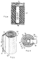
- Figure 4 is an elevational cross-sectional view of a cell utilizing an electrode made by the method of the instant invention.
- Figure 5 is a perspective view of a spirally wound cell pack, partially broken away, utilizing an electrode made by the method of the instant invention.
- Figure 6 is a top view of the cell pack of Figure 5 showing the contact to the battery terminal.
- the electrode 11 is preferably a positive electrode and is designed to be rolled up with a counter electrode and interleaved separator to form a spirally wound cell pack for an electrochemical cell.
- the substrate for the electrode may be in the form of a flexible foam metal plate 13 having a porosity typically from about 80 to about 95 percent, having one of its major surfaces impregnated with an electrochemically active material 15 namely nickel hydroxide paste as is well known in the art.
- the electrode may be formed of a perforated metal substrate having at least two major surfaces, wherein one of the major surfaces is covered with porous sintered nickel adhered thereto and impregnated with active nickel hydroxide (by "nickel hydroxide” herein is also included NiOOH).
- nickel hydroxide herein is also included NiOOH.
- a conductive contact area is required to carry current from the electrode to a terminal of the electrochemical cell. Furthermore, in some cells it is necessary to provide a contact tab attached to the conductive area to make such a connection. It is preferable to attach such a tab by welding it to the conductive area. In the past, this has been difficult to achieve because of the lack of metal of adequate mass in the conductive contact area for the welding process.
- Figure 1 shows a conductive area 12 of electrode 11 which has been converted or reduced to nickel metal for conductivity.
- This contact area of nickel metal is achieved by exposing the nickel hydroxide impregnated electrode to a heat source in an atmosphere containing a reducing gas such as hydrogen.
- Conductive tab 14 is then conventionally welded to electrode 11 at the converted area 12 as required.
- FIG. 2 schematically shows the heat source 30 in a hot hydrogen atmosphere 31.
- Any heat source which can be directed at the selected area and which can be shrouded with hydrogen can be used. Examples include a plasma source, a laser, an induction heater, a microwave, a resistance heater or a plate lab oven directed by means of a heat sink.
- the heat source should be able to reach the temperature of 1,600°F (871°C) plus or minus 50°F (28°C) to provide preferred times for exposure. Lower temperatures would require a longer exposure time to convert all the nickel hydroxide.
- shrouding of the heat source is done with between 5-10% hydrogen gas mixed with an inert gas, such as nitrogen, argon, helium, or any of the noble gases.
- an inert gas such as nitrogen, argon, helium, or any of the noble gases.
- the time interval of the exposure typically can extend from 10 seconds down to one-half second at the higher temperatures. It is necessary that the source of the hydrogen atmosphere be steady flowing throughout the process in order to remove the moisture or water vapor produced by the reaction. The flow of hydrogen, furthermore, will drive off any organics or binders remaining in the converted nickel metal so that maximum conductivity is achieved. The resulting nickel metal will provide a material suitable for welding a contact tab.
- FIG 3 shows an alternative embodiment in which a plurality of electrodes 28, 29 can be made using a single substrate strip 21 impregnated with an electrochemically active material 23.
- the substrate strip may be in the form of a foam metal substrate impregnated with an electrochemically active material, namely nickel hydroxide paste, or it may be in the form of a perforated metal plate covered with porous sintered nickel and impregnated with the active nickel hydroxide.
- the strip should be wide enough to form more than one electrode of desired size. To subdivide the strip into the desired size and shape electrodes required, a dynamic or continuous version of the method of exposure or conversion described above is used.
- the strip Before the strip is slit or cut into the desired sizes, it is exposed by moving it in the direction of arrow 19 in relation to a directed heat source in a hydrogen gas atmosphere as described above and shown schematically in Fig. 2.
- the exposure is preferably limited to the area immediately adjacent line 25 along which the electrode strip is to be slit or cut.
- the nickel hydroxide along the slit line is reduced or converted to nickel metal upon exposure and thus cutting or slitting of the densified nickel metal can be easily achieved.
- It will also provide metallized edges 26 and 27 for the finished electrodes. These edges will be electrically conductive and can be used as conductive contacts connecting the electrodes and terminals of the electrochemical cells in which the electrodes are inserted.
- the method described above thus can be used to produce multiple electrode strips in assorted shapes and sizes from a single impregnated substrate by selectively exposing the substrate to a directed heat source in a hydrogen atmosphere along selected lines.
- the substrate can be then cut or slit into the desired widths and cross cut to size.
- the conversion process can be selectively controlled so that the exposure will result in reduced nickel metal along the slit or cutting lines which will provide the conductive area for current collection to a battery terminal, and maximize the amount of active material remaining in the electrode.
- Figure 4 shows a cell having a spirally wound construction.
- the cell includes the electrode and contact tab of the instant invention of the type illustrated in Figure 1.
- An electrically conductive casing 40 forms one terminal of the cell.
- a winding spindle 41 formed of insulating material and having spirally wound thereon a four-layer assembly consisting of a first layer 42 which is the negative plate, a second layer 43 formed of a porous insulating separator, a third layer 44 which is a positive plate, and a fourth layer 45 which is a porous insulating separator.
- the positive plate 44 has a conductive area made by the conversion technique as described above.
- Contact tab 46 is welded to the conductive area and provides a connection between the positive electrode and the positive terminal 51 cell.
- the conversion method described above can also be used to provide a conductive area for contact adherence for the negative plate.
- an electrode impregnated with cadmium hydroxide is selectively exposed to at least partially remove or vaporize the cadmium hydroxide (through the intermediate species, cadmium metal) at a selected conductive area.
- Contact tab 48 would then be welded primarily to the substrate and to any residual cadmium metal left following the conversion process, at such a selected area and the negative plate connected to the cell casing 40 through contact tab 48.
- Figure 5 show one of the electrodes 28, 29 formed by the method described above in conjunction with Figures 2 and 3, used in a spirally wound electrochemical cell.
- the wound cell comprises positive electrode 28, a first separator 37, negative electrode 30 and a second separator 32.
- Plates 28 and 30 with separators 37 and 32 there between are spirally wound to form coil cell pack 50.
- Plates 28 and 30 are transversely offset from one another as well as separators 31 and 32, to provide an extended longitudinal edge 26 of plate 28 at one end of coil 50 and an extended edge 33 of plate 30 at the opposite end of coil 50.
- the extended edges 26 and 33 are conductive edges which can be formed of reduced metal by the conversion method described above.
- the conductive edge can be achieved by exposing the cadmium hydroxide coated substrate to a heat source in a hydrogen atmosphere to vaporize the cadmium hydroxide via cadmium metal as described above with respect to the negative electrode.
- current collector 55 is provided at one end of the coil 50.
- a second current collector is provided at the lower end of coil 50 (Fig. 6) to contact edge 33 but illustration thereof is omitted because it is identical to collector 55.
- Current collector 55 comprises two substantially planar leg portions 56 and 57 and a raised central portion 58 attached to the leg portions 56 and 57. The leg portions 56 and 57 contact (such as by percussion weld) the extended conductive edge 26 of the positive electrode.
- the raised central portion 58 is welded to the base of a cover disc for the cell can which forms the positive terminal of the electrochemical cell can.
- the central portion of the negative current collector (not shown) is welded to the base of the cell can which forms the negative terminal of the cell.
- the invention has been disclosed with particular reference to producing the positive electrode of an electrochemical cell.
- the conversion method can be used to produce negative electrodes having selected conductive areas.
- the process of the instant invention can be used to convert cadmium in an electrode impregnated with cadmium hydroxide to reduced cadmium metal and then vaporize the cadmium metal at selective areas.
- the conversion technique can also be used, for instance, to convert an electrode impregnated with cobalt hydroxide to reduced cobalt metal at a selected area.
- the temperature of the heat source could be varied depending on the particular reducible metal used if desired.
Landscapes
- Chemical & Material Sciences (AREA)
- Chemical Kinetics & Catalysis (AREA)
- Electrochemistry (AREA)
- General Chemical & Material Sciences (AREA)
- Engineering & Computer Science (AREA)
- Manufacturing & Machinery (AREA)
- Mechanical Engineering (AREA)
- Battery Electrode And Active Subsutance (AREA)
- Cell Electrode Carriers And Collectors (AREA)
- Connection Of Batteries Or Terminals (AREA)
- Manufacturing Of Printed Wiring (AREA)
- Electrodes Of Semiconductors (AREA)
Claims (7)
- Verfahren zur Herstellung einer Elektrode (11) für eine wiederaufladbare elektrochemische Zelle, mit den Schritten:
Bereitstellen eines elektrisch leitfähigen porösen Substrates (13) mit mindestens zwei Hauptflächen und einer Schicht (15) aus einem elektrochemisch aktiven Material, die mindestens an einer der Hauptflächen angebracht ist und mindestens eine der Hauptflächen mindestens teilweise bedeckt, und Imprägnieren der Poren des Substrates, wobei das aktive Material eine reduzierbare Art eines Metalls ist, und
das elektrochemisch aktive Material an einer Kontaktfläche einer Wärmequelle in einer Atmosphäre aussetzen, welche ein reduzierendes Gas (30,31) enthält, um die reduzierbare Art des Metalls in die Metallform umzuwandeln und eine an dem Substrat angebrachte elektrisch leitfähige Kontaktfläche (12) zu schaffen. - Verfahren nach Anspruch 1, bei dem das Substrat Schaummetallfasern aufweist.
- Verfahren nach Anspruch 1 oder 2, das zusätzlich den Schritt des Anbringens einer leitfähigen Lasche (14) an der elektrisch leitfähigen Kontaktfläche (12) umfaßt.
- Verfahren nach einem der Ansprüche 1 bis 3, bei dem das reduzierende Gas Wasserstoff ist.
- Verfahren nach einem der Ansprüche 1 bis 4, bei dem die Wärmequelle bei 871°C (1600°F) ± 28°C (50°F) gehalten wird.
- Verfahren nach einem der Ansprüche 1 bis 5, mit den Schritten des Bewegens des Substrates relativ zu der Wärmequelle, um einen Streifen an dem Substrat als Kontaktfläche zu wählen, sowie des Schneidens des Substrates in mehrere Elektroden entlang dieses Streifens.
- Verfahren nach einem der Ansprüche 1 bis 6, bei dem die reduzierbare Art eines Metalls Nickelhydroxid ist und der Schritt des Aussetzens das Nickelhydroxid in Nickelmetall umwandelt.
Applications Claiming Priority (2)
| Application Number | Priority Date | Filing Date | Title |
|---|---|---|---|
| US07/585,575 US5196281A (en) | 1990-09-20 | 1990-09-20 | Electrode having a conductive contact area and method of making the same |
| US585575 | 1990-09-20 |
Publications (2)
| Publication Number | Publication Date |
|---|---|
| EP0481605A1 EP0481605A1 (de) | 1992-04-22 |
| EP0481605B1 true EP0481605B1 (de) | 1995-06-07 |
Family
ID=24342049
Family Applications (1)
| Application Number | Title | Priority Date | Filing Date |
|---|---|---|---|
| EP91308532A Expired - Lifetime EP0481605B1 (de) | 1990-09-20 | 1991-09-18 | Verfahren zur Herstellung einer Elektrode mit leitender Kontaktfläche. |
Country Status (5)
| Country | Link |
|---|---|
| US (2) | US5196281A (de) |
| EP (1) | EP0481605B1 (de) |
| AT (1) | ATE123591T1 (de) |
| CA (1) | CA2051826C (de) |
| DE (1) | DE69110239T2 (de) |
Families Citing this family (20)
| Publication number | Priority date | Publication date | Assignee | Title |
|---|---|---|---|---|
| DE4019256A1 (de) * | 1990-06-15 | 1991-12-19 | Varta Batterie | Verfahren zum anbringen eines ableiters an eine ein metallschaumgeruest als traegerteil enthaltende elektrode |
| CN1091553A (zh) * | 1992-11-20 | 1994-08-31 | 国家标准公司 | 电池电极的基质及其制造方法 |
| CA2110097C (en) * | 1992-11-30 | 2002-07-09 | Soichiro Kawakami | Secondary battery |
| US5314544A (en) * | 1993-05-18 | 1994-05-24 | Saft America, Inc. | High-speed non-destructive cleaning of metal foam substrate of electromechanical cell electrodes |
| JP3509031B2 (ja) * | 1993-12-10 | 2004-03-22 | 片山特殊工業株式会社 | リード付き金属多孔体の製造方法及び該方法により製造されたリード付き金属多孔体 |
| KR0148826B1 (ko) * | 1994-05-20 | 1998-10-15 | 전성원 | 붕소가 첨가된 고밀도 수산화니켈과 그의 제조방법 |
| US5840444A (en) * | 1995-01-18 | 1998-11-24 | Matsushita Electric Industrial Co., Ltd. | Electrode for storage battery and process for producing the same |
| JP2976863B2 (ja) * | 1995-10-09 | 1999-11-10 | 松下電器産業株式会社 | 電池用電極の製造法 |
| US5584892A (en) * | 1995-06-06 | 1996-12-17 | Hughes Aircraft Company | Process for producing nickel electrode having lightweight substrate |
| JP3373976B2 (ja) * | 1995-06-12 | 2003-02-04 | 三洋電機株式会社 | 非円形スパイラル電極体を内蔵する電池の製造方法 |
| US5981108A (en) * | 1995-10-09 | 1999-11-09 | Matsushita Electric Industrial Co, Ltd. | Electrodes for battery and method of fabricating the same |
| DE69737922T2 (de) * | 1996-08-22 | 2008-04-03 | Dai Nippon Printing Co., Ltd. | Elektrodenplatte für Sekundärbatterie mit nichtwässerigem Elektrolyt sowie Herstellungsverfahren |
| US6080283A (en) * | 1997-11-25 | 2000-06-27 | Eveready Battery Company, Inc. | Plasma treatment for metal oxide electrodes |
| US6238819B1 (en) | 1998-01-23 | 2001-05-29 | Stork, N.V. | Metal foam support, electrode and method of making same |
| US6492062B1 (en) | 2000-08-04 | 2002-12-10 | The Gillette Company | Primary alkaline battery including nickel oxyhydroxide |
| US6489056B1 (en) | 2000-09-18 | 2002-12-03 | The Gillette Company | Battery including a hydrogen-absorbing cathode material |
| US6740451B2 (en) | 2001-12-20 | 2004-05-25 | The Gillette Company | Gold additive for a cathode including nickel oxyhydroxide for an alkaline battery |
| US7081319B2 (en) * | 2002-03-04 | 2006-07-25 | The Gillette Company | Preparation of nickel oxyhydroxide |
| US9520588B2 (en) * | 2011-09-14 | 2016-12-13 | Panasonic Intellectual Property Management Co., Ltd. | Nonaqueous electrolyte secondary cell |
| GB201203997D0 (en) * | 2012-03-07 | 2012-04-18 | Bae Systems Plc | Electrical energy storage structures |
Family Cites Families (18)
| Publication number | Priority date | Publication date | Assignee | Title |
|---|---|---|---|---|
| DE546290C (de) * | 1930-07-20 | 1932-03-11 | Ig Farbenindustrie Ag | Verfahren zur Erhoehung der Haltbarkeit von durch Sintern von Eisenpulver hergestellten Elektroden fuer alkalische Sammler |
| GB1370777A (en) * | 1970-10-06 | 1974-10-16 | Ever Ready Co | Electrodes for electro-chemical cells |
| US4060676A (en) * | 1975-06-06 | 1977-11-29 | P. R. Mallory & Co. Inc. | Metal periodate organic electrolyte cells |
| US4029132A (en) * | 1976-05-24 | 1977-06-14 | Westinghouse Electric Corporation | Method of preparing high capacity nickel electrode powder |
| DE2632073A1 (de) * | 1976-07-16 | 1978-01-19 | Schlemmer Fa Manfred | Akkumulator |
| US4224392A (en) * | 1977-12-16 | 1980-09-23 | Oswin Harry G | Nickel-oxide electrode structure and method of making same |
| JPS559143A (en) * | 1978-07-07 | 1980-01-23 | Hochiki Corp | Temperature detector |
| SU725124A1 (ru) * | 1978-10-20 | 1980-03-30 | Предприятие П/Я Р-6836 | Способ изготовлени безламельного кадмиевого электрода щелочного аккумул тора |
| US4330603A (en) * | 1981-01-29 | 1982-05-18 | The United States Of America As Represented By The United States Department Of Energy | High capacity nickel battery material doped with alkali metal cations |
| DE3142091C2 (de) * | 1981-10-23 | 1984-05-30 | Deutsche Automobilgesellschaft Mbh, 7000 Stuttgart | Verfahren zur Herstellung einer stabilen Verbindung zwischen einem Elektrodengerüst aus einem metallisierten Faserkörper und einer Stromableiterfahne |
| US4443526A (en) * | 1982-03-03 | 1984-04-17 | Westinghouse Electric Corp. | NiCO3 Electrode material and electrode |
| US4425192A (en) * | 1982-12-07 | 1984-01-10 | Allied Corporation | Method of forming battery electrodes |
| JPS59196574A (ja) * | 1983-04-21 | 1984-11-07 | Toshiba Battery Co Ltd | 非水電解液電池 |
| JPS61214363A (ja) * | 1985-03-19 | 1986-09-24 | Sanyo Electric Co Ltd | 蓄電池用極板 |
| EP0353837B1 (de) * | 1988-07-19 | 1994-07-27 | Yuasa Corporation | Nickelelektrode für eine alkalische Batterie |
| GB8828829D0 (en) * | 1988-12-09 | 1989-01-18 | Lilliwyte Sa | Electrochemical cell |
| US4975035A (en) * | 1989-01-13 | 1990-12-04 | Jerry Kuklinski | Method of making a nickel hydroxide-containing cathode for alkaline batteries |
| US5023155A (en) * | 1989-11-06 | 1991-06-11 | Energy Research Corporation | Nickel electrode for alkaline batteries |
-
1990
- 1990-09-20 US US07/585,575 patent/US5196281A/en not_active Expired - Fee Related
-
1991
- 1991-09-18 EP EP91308532A patent/EP0481605B1/de not_active Expired - Lifetime
- 1991-09-18 AT AT91308532T patent/ATE123591T1/de not_active IP Right Cessation
- 1991-09-18 DE DE69110239T patent/DE69110239T2/de not_active Expired - Fee Related
- 1991-09-19 CA CA002051826A patent/CA2051826C/en not_active Expired - Fee Related
-
1992
- 1992-12-03 US US07/999,789 patent/US5336276A/en not_active Expired - Fee Related
Non-Patent Citations (1)
| Title |
|---|
| CHEMICAL ABSTRACTS, vol. 93, no. 14, 6 October 1980, Columbus, Ohio,US; abstract no. 135001S, MATSUSHITA ELECTRIC INDUSTRIAL: 'Iron electrode for primary batteries' page 152 ;column 1 ;& JP-A-80009143(MATSUSHITA ELECTRIC INDUSTRIAL CO.) (07-03-1980) * |
Also Published As
| Publication number | Publication date |
|---|---|
| HK1005199A1 (en) | 1998-12-24 |
| CA2051826C (en) | 1996-03-05 |
| US5196281A (en) | 1993-03-23 |
| US5336276A (en) | 1994-08-09 |
| DE69110239D1 (de) | 1995-07-13 |
| ATE123591T1 (de) | 1995-06-15 |
| EP0481605A1 (de) | 1992-04-22 |
| DE69110239T2 (de) | 1995-10-19 |
| CA2051826A1 (en) | 1992-03-21 |
Similar Documents
| Publication | Publication Date | Title |
|---|---|---|
| EP0481605B1 (de) | Verfahren zur Herstellung einer Elektrode mit leitender Kontaktfläche. | |
| CA2161287C (en) | Electrode plate for battery and process for producing the same | |
| CA2147975C (en) | Bifunctional airelectrode | |
| US5599637A (en) | Performance zinc anode for batteries | |
| CA1301834C (en) | Cell arrangement for a filter press type stack of cells and method for producing the arrangement | |
| EP0969538B1 (de) | Batterie | |
| CA2021558C (en) | Wound electrode assembly for an electrochemical cell | |
| US3486940A (en) | Storage battery having a positive electrode comprising a supporting base of titanium nitride having a surface film of non-polarizing material | |
| US8563150B2 (en) | Device for catalytic recombination of gases for alkaline batteries with shortened zinc anode | |
| HK1005050B (en) | Wound electrode assembly for an electrochemical cell | |
| GB1568544A (en) | Battery assembly | |
| US3600230A (en) | Gas-depolarized cell with hydrophobic-resin-containing cathode | |
| US5122426A (en) | Gas-tight, sealed alkaline secondary cell | |
| US5458993A (en) | Non-aqueous electrolyte battery and method of manufacturing same | |
| WO1999035701A1 (en) | Zinc based electrochemical cell | |
| US5712060A (en) | Alkaline storage cell | |
| HK1005199B (en) | A process for forming an electrode having a conductive contact area | |
| US20050277024A1 (en) | Nickel precoat for electrode plates | |
| JPS59111261A (ja) | アルカリ蓄電池用極板の製造法 | |
| JPS5880265A (ja) | 電池 | |
| JPS59105264A (ja) | アルカリ蓄電池極板の製造法 | |
| JPH06251771A (ja) | 電極基体の製造法 | |
| KR19980038001A (ko) | 전지의 전극판 및 그 제조방법 | |
| JPS6174262A (ja) | 溶融塩燃料電池用カソ−ドの製造法 | |
| HK1114467B (en) | Device for catalytic recombination of gases for alkaline batteries with shortened zinc anode |
Legal Events
| Date | Code | Title | Description |
|---|---|---|---|
| PUAI | Public reference made under article 153(3) epc to a published international application that has entered the european phase |
Free format text: ORIGINAL CODE: 0009012 |
|
| AK | Designated contracting states |
Kind code of ref document: A1 Designated state(s): AT BE CH DE DK ES FR GB IT LI LU NL SE |
|
| 17P | Request for examination filed |
Effective date: 19921005 |
|
| 17Q | First examination report despatched |
Effective date: 19930730 |
|
| GRAA | (expected) grant |
Free format text: ORIGINAL CODE: 0009210 |
|
| AK | Designated contracting states |
Kind code of ref document: B1 Designated state(s): AT BE CH DE DK ES FR GB IT LI LU NL SE |
|
| PG25 | Lapsed in a contracting state [announced via postgrant information from national office to epo] |
Ref country code: IT Free format text: LAPSE BECAUSE OF FAILURE TO SUBMIT A TRANSLATION OF THE DESCRIPTION OR TO PAY THE FEE WITHIN THE PRE;WARNING: LAPSES OF ITALIAN PATENTS WITH EFFECTIVE DATE BEFORE 2007 MAY HAVE OCCURRED AT ANY TIME BEFORE 2007. THE CORRECT EFFECTIVE DATE MAY BE DIFFERENT FROM THE ONE RECORDED.SCRIBED TIME-LIMIT Effective date: 19950607 Ref country code: DK Effective date: 19950607 Ref country code: AT Effective date: 19950607 |
|
| REF | Corresponds to: |
Ref document number: 123591 Country of ref document: AT Date of ref document: 19950615 Kind code of ref document: T |
|
| REF | Corresponds to: |
Ref document number: 69110239 Country of ref document: DE Date of ref document: 19950713 |
|
| PGFP | Annual fee paid to national office [announced via postgrant information from national office to epo] |
Ref country code: LU Payment date: 19950801 Year of fee payment: 5 |
|
| PGFP | Annual fee paid to national office [announced via postgrant information from national office to epo] |
Ref country code: CH Payment date: 19950810 Year of fee payment: 5 |
|
| PGFP | Annual fee paid to national office [announced via postgrant information from national office to epo] |
Ref country code: NL Payment date: 19950811 Year of fee payment: 5 Ref country code: SE Payment date: 19950811 Year of fee payment: 5 |
|
| PGFP | Annual fee paid to national office [announced via postgrant information from national office to epo] |
Ref country code: DK Payment date: 19950814 Year of fee payment: 5 |
|
| PGFP | Annual fee paid to national office [announced via postgrant information from national office to epo] |
Ref country code: AT Payment date: 19950816 Year of fee payment: 5 |
|
| PG25 | Lapsed in a contracting state [announced via postgrant information from national office to epo] |
Ref country code: SE Effective date: 19950907 |
|
| PGFP | Annual fee paid to national office [announced via postgrant information from national office to epo] |
Ref country code: ES Payment date: 19950914 Year of fee payment: 5 |
|
| PG25 | Lapsed in a contracting state [announced via postgrant information from national office to epo] |
Ref country code: ES Free format text: LAPSE BECAUSE OF FAILURE TO SUBMIT A TRANSLATION OF THE DESCRIPTION OR TO PAY THE FEE WITHIN THE PRESCRIBED TIME-LIMIT Effective date: 19950918 |
|
| PGFP | Annual fee paid to national office [announced via postgrant information from national office to epo] |
Ref country code: BE Payment date: 19950929 Year of fee payment: 5 |
|
| ET | Fr: translation filed | ||
| PLBE | No opposition filed within time limit |
Free format text: ORIGINAL CODE: 0009261 |
|
| STAA | Information on the status of an ep patent application or granted ep patent |
Free format text: STATUS: NO OPPOSITION FILED WITHIN TIME LIMIT |
|
| 26N | No opposition filed | ||
| REG | Reference to a national code |
Ref country code: GB Ref legal event code: 732E |
|
| REG | Reference to a national code |
Ref country code: CH Ref legal event code: PUE Owner name: GATES ENERGY PRODUCTS, INC. TRANSFER- EVEREADY BAT |
|
| PG25 | Lapsed in a contracting state [announced via postgrant information from national office to epo] |
Ref country code: LU Free format text: LAPSE BECAUSE OF NON-PAYMENT OF DUE FEES Effective date: 19960918 |
|
| PG25 | Lapsed in a contracting state [announced via postgrant information from national office to epo] |
Ref country code: CH Effective date: 19960930 Ref country code: BE Effective date: 19960930 Ref country code: LI Effective date: 19960930 |
|
| REG | Reference to a national code |
Ref country code: FR Ref legal event code: TP |
|
| BERE | Be: lapsed |
Owner name: GATES ENERGY PRODUCTS INC. Effective date: 19960930 |
|
| PG25 | Lapsed in a contracting state [announced via postgrant information from national office to epo] |
Ref country code: NL Effective date: 19970401 |
|
| REG | Reference to a national code |
Ref country code: CH Ref legal event code: PL |
|
| NLV4 | Nl: lapsed or anulled due to non-payment of the annual fee |
Effective date: 19970401 |
|
| BECA | Be: change of holder's address |
Free format text: 970917 *EVEREADY BATTERY CY INC.:25225 DETROIT ROAD, WESTLAKE OHIO 44145 |
|
| PGFP | Annual fee paid to national office [announced via postgrant information from national office to epo] |
Ref country code: DE Payment date: 19990902 Year of fee payment: 9 Ref country code: FR Payment date: 19990902 Year of fee payment: 9 Ref country code: GB Payment date: 19990902 Year of fee payment: 9 |
|
| PG25 | Lapsed in a contracting state [announced via postgrant information from national office to epo] |
Ref country code: GB Free format text: LAPSE BECAUSE OF NON-PAYMENT OF DUE FEES Effective date: 20000918 |
|
| GBPC | Gb: european patent ceased through non-payment of renewal fee |
Effective date: 20000918 |
|
| PG25 | Lapsed in a contracting state [announced via postgrant information from national office to epo] |
Ref country code: FR Free format text: LAPSE BECAUSE OF NON-PAYMENT OF DUE FEES Effective date: 20010531 |
|
| PG25 | Lapsed in a contracting state [announced via postgrant information from national office to epo] |
Ref country code: DE Free format text: LAPSE BECAUSE OF NON-PAYMENT OF DUE FEES Effective date: 20010601 |
|
| REG | Reference to a national code |
Ref country code: FR Ref legal event code: ST |