EP0480974B1 - Verteilervorrichtung - Google Patents
Verteilervorrichtung Download PDFInfo
- Publication number
- EP0480974B1 EP0480974B1 EP90910655A EP90910655A EP0480974B1 EP 0480974 B1 EP0480974 B1 EP 0480974B1 EP 90910655 A EP90910655 A EP 90910655A EP 90910655 A EP90910655 A EP 90910655A EP 0480974 B1 EP0480974 B1 EP 0480974B1
- Authority
- EP
- European Patent Office
- Prior art keywords
- rotatable
- distributor device
- line
- lines
- connectable
- Prior art date
- Legal status (The legal status is an assumption and is not a legal conclusion. Google has not performed a legal analysis and makes no representation as to the accuracy of the status listed.)
- Expired - Lifetime
Links
Images


Classifications
-
- F—MECHANICAL ENGINEERING; LIGHTING; HEATING; WEAPONS; BLASTING
- F16—ENGINEERING ELEMENTS AND UNITS; GENERAL MEASURES FOR PRODUCING AND MAINTAINING EFFECTIVE FUNCTIONING OF MACHINES OR INSTALLATIONS; THERMAL INSULATION IN GENERAL
- F16K—VALVES; TAPS; COCKS; ACTUATING-FLOATS; DEVICES FOR VENTING OR AERATING
- F16K11/00—Multiple-way valves, e.g. mixing valves; Pipe fittings incorporating such valves
- F16K11/02—Multiple-way valves, e.g. mixing valves; Pipe fittings incorporating such valves with all movable sealing faces moving as one unit
- F16K11/06—Multiple-way valves, e.g. mixing valves; Pipe fittings incorporating such valves with all movable sealing faces moving as one unit comprising only sliding valves, i.e. sliding closure elements
- F16K11/072—Multiple-way valves, e.g. mixing valves; Pipe fittings incorporating such valves with all movable sealing faces moving as one unit comprising only sliding valves, i.e. sliding closure elements with pivoted closure members
- F16K11/074—Multiple-way valves, e.g. mixing valves; Pipe fittings incorporating such valves with all movable sealing faces moving as one unit comprising only sliding valves, i.e. sliding closure elements with pivoted closure members with flat sealing faces
-
- F—MECHANICAL ENGINEERING; LIGHTING; HEATING; WEAPONS; BLASTING
- F16—ENGINEERING ELEMENTS AND UNITS; GENERAL MEASURES FOR PRODUCING AND MAINTAINING EFFECTIVE FUNCTIONING OF MACHINES OR INSTALLATIONS; THERMAL INSULATION IN GENERAL
- F16K—VALVES; TAPS; COCKS; ACTUATING-FLOATS; DEVICES FOR VENTING OR AERATING
- F16K11/00—Multiple-way valves, e.g. mixing valves; Pipe fittings incorporating such valves
- F16K11/10—Multiple-way valves, e.g. mixing valves; Pipe fittings incorporating such valves with two or more closure members not moving as a unit
- F16K11/14—Multiple-way valves, e.g. mixing valves; Pipe fittings incorporating such valves with two or more closure members not moving as a unit operated by one actuating member, e.g. a handle
- F16K11/16—Multiple-way valves, e.g. mixing valves; Pipe fittings incorporating such valves with two or more closure members not moving as a unit operated by one actuating member, e.g. a handle which only slides, or only turns, or only swings in one plane
- F16K11/163—Multiple-way valves, e.g. mixing valves; Pipe fittings incorporating such valves with two or more closure members not moving as a unit operated by one actuating member, e.g. a handle which only slides, or only turns, or only swings in one plane only turns
- F16K11/166—Multiple-way valves, e.g. mixing valves; Pipe fittings incorporating such valves with two or more closure members not moving as a unit operated by one actuating member, e.g. a handle which only slides, or only turns, or only swings in one plane only turns with the rotating spindles at right angles to the closure members
-
- Y—GENERAL TAGGING OF NEW TECHNOLOGICAL DEVELOPMENTS; GENERAL TAGGING OF CROSS-SECTIONAL TECHNOLOGIES SPANNING OVER SEVERAL SECTIONS OF THE IPC; TECHNICAL SUBJECTS COVERED BY FORMER USPC CROSS-REFERENCE ART COLLECTIONS [XRACs] AND DIGESTS
- Y10—TECHNICAL SUBJECTS COVERED BY FORMER USPC
- Y10T—TECHNICAL SUBJECTS COVERED BY FORMER US CLASSIFICATION
- Y10T137/00—Fluid handling
- Y10T137/8593—Systems
- Y10T137/86493—Multi-way valve unit
- Y10T137/86863—Rotary valve unit
-
- Y—GENERAL TAGGING OF NEW TECHNOLOGICAL DEVELOPMENTS; GENERAL TAGGING OF CROSS-SECTIONAL TECHNOLOGIES SPANNING OVER SEVERAL SECTIONS OF THE IPC; TECHNICAL SUBJECTS COVERED BY FORMER USPC CROSS-REFERENCE ART COLLECTIONS [XRACs] AND DIGESTS
- Y10—TECHNICAL SUBJECTS COVERED BY FORMER USPC
- Y10T—TECHNICAL SUBJECTS COVERED BY FORMER US CLASSIFICATION
- Y10T137/00—Fluid handling
- Y10T137/8593—Systems
- Y10T137/87153—Plural noncommunicating flow paths
- Y10T137/87161—With common valve operator
Definitions
- the invention relates to a distributor device for selectively connecting one of a plurality of incoming lines with an outgoing line and an incoming line with one of a plurality of outgoing lines.
- Distribution devices of the type mentioned are known and e.g. described in DE-A-35 45 681.
- the distribution device has several incoming and a corresponding number of outgoing lines, so that a relative rotation of the body against each other by 360 ° or more is only possible if the lines consist of elastically deformable materials and are sufficiently long.
- Another disadvantage with which the known device is afflicted is that the number of different medium-conducting connections is relatively small.
- DE-A-35 09 764 describes a device for the optional connection of lines for flowable media and is designed in the manner of a linear slide, the parts of which perform linear reciprocating movements, even when two linear slides, which are in one shared housing, work together.
- the invention is based on the task To further develop the distributor device without undue constructive effort so that several connections between medium sources and consumers can be established in the smallest space.
- control elements which can be connected to the lines and are spatially separated from one another, each with a stationary body which can be connected to the incoming or outgoing lines, and a body which can be rotated with respect to the latter and which assumes several working positions and can be connected to the outgoing or incoming lines Solved body, the line in its working positions with a line of the stationary body is medium-carrying.
- a particularly useful embodiment provides that the rotatable bodies are driven by at least one servomotor. If it is a distributor device, the rotatable bodies of which are formed from circular disks, then it is expedient if the radial outer sides of the bodies are designed as gear wheels, which are connected to a gear wheel of the motor work together. In this simplest embodiment of the invention there is also the possibility that the motor meshes with the gear of one rotatable body, while this body meshes with the other rotatable body. In both cases it is achieved that the rotatable bodies are in opposite directions.
- the distributor device can of course also consist of several control elements, e.g. three, four, etc. exist.
- the rotatable bodies can be connected to one another via gearwheels, which are adjustable between an effective working position that works with the rotatable bodies and an ineffective working position in which they do not work with the rotatable bodies.
- the distributor device is to be used in a system with several medium sources and consumers, then it is expedient if the servomotor and the gearwheels cooperating with an actuating device can be connected to a central control device.
- the control device can be a computer system by means of which not only the type of connection but also its duration can be controlled.
- a particularly advantageous embodiment of the invention provides that the stationary body has a plurality of circular openings with outwardly projecting connecting pieces to which the lines can be connected and which are at the same distance from the axis of rotation of the rotatable body, and that the respective body has a single circular opening with a connecting piece connected to it, which in the working positions of the rotatable body is aligned with one of the openings of the stationary body.
- These measures can also be taken such that the breakthrough of the stationary body and / or the breakthroughs of the rotatable body are surrounded by sealing bodies.
- the distributor device shown in FIG. 1 consists of two control elements 60 and 62, which are identical in mirror image, and each consist of a stationary body 10 and 110 and a rotatable body 14 and 114.
- the control element 62 shown in FIG. 1 is connected to a medium source (not shown in detail) and to a consumer 50.
- the medium is fed to the control element 62 via the line 127, which is connected to a nozzle 111 by means of a clamp 128.
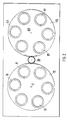
- the stationary body 110 has a plurality of connecting pieces 111, as shown in particular in FIG. 2.
- the rotatable body 114 has a single opening 116, in which a nozzle 115 is inserted, which is connected to the line 122 via a clamp 123.
- the line 140 connects to the line 122, which is connected to the line 146 in a medium-carrying manner via a rotary flange 144.
- the rotatable body 114 is rotatable about the vertical axis 102 in the direction of the arrow 142.
- the rotatable body 114 is mounted in the bearing body 130.
- the rotatable body 114 On its radial outer side, the rotatable body 114 has a gear wheel 119 which meshes with the gear wheel 20 of the motor 3. If the rotatable body 114 is now rotated about its axis 102, then the connecting line 140 also rotates in the rotary flange 144, by means of which a rotatable connection between the line 140 and the line 146 can be established.
- the left control element 60 shown in FIG. 1 is mirror-inverted to the control element 62, so that it has a plurality of connecting pieces 11 which can be connected to outgoing lines 27 by means of clamps 28.
- the radial outside of the rotatable body 14 has an external gear 19.
- the rotatable body 14 has a single bore 16, in which a nozzle 15 is arranged and surrounded by the sealing ring 18.
- the sealing ring 118 has the same function as the sealing ring 18.
- the connector 15 is releasably connectable to the incoming line 22 via a clamp 23.
- the incoming line 22 is connected to the line 44, which in turn can be rotatably connected to the line 46 via the rotary flange 44.
- the rotatable body 14 or 114 can cooperate with an actuator which can adjust it in the direction of the arrow 52 or 152 in cycles.
- the motor 3 When the motor 3 is switched on, the left rotatable body shown in FIG. 1 moves in the direction of the arrow 42, while the right rotatable body 114 is rotated in the direction of the arrow 142.
- the rotary flange 44 or 144 has an axis of rotation, which is identical to the axis of rotation 2 or 102 or runs parallel. This prevents the line 40 or 140 from being mechanically stressed.
- This probably the simplest embodiment of the invention can be expanded, for example, by connecting a plurality of control elements 60 and 62 to one another.
- the control elements can be driven by a common motor 3, the rotary movement from one rotatable body to the other being able to take place via gearwheels which can assume effective or ineffective working positions. In this way, a specific control element can be separated from the engine 3 in a targeted manner. In this way, a large number of media-carrying connections can be made without having to make the distributor device significantly larger.
- Fig. 2 shows that the connecting pieces 11 and 111 are evenly distributed around the axis of rotation 2 and 102.
- Fig. 3 shows that the rotatable body 14 and 114 has only a single nozzle 15 and 115, which is matched to the dimensions of the nozzle 11 and 111.
Landscapes
- Engineering & Computer Science (AREA)
- General Engineering & Computer Science (AREA)
- Mechanical Engineering (AREA)
- Multiple-Way Valves (AREA)
- Infusion, Injection, And Reservoir Apparatuses (AREA)
Abstract
Description
- Die Erfindung betrifft eine Verteilervorrichtung zum wahlweisen Verbinden einer von mehreren ankommenden Leitungen mit einer abgehenden Leitung sowie einer ankommenden Leitung mit einer von mehreren abgehenden Leitungen.
- Verteilervorrichtungen der eingangs genannten Art sind bekannt und z.B. in der DE-A- 35 45 681 beschrieben. Dabei besitzt die Verteilervorrichtung mehrere ankommende sowie entsprechend viele abgehende Leitungen, so daß eine Relativverdrehung der Körper gegeneinander um 360° oder mehr nur dann möglich ist, wenn die Leitungen aus elastisch verformbaren Werkstoffen bestehen und hinreichend lang sind. Ein weiterer Nachteil, mit dem die bekannte Vorrichtung behaftet ist, besteht darin, daß die Anzahl der verschiedenen mediumleitenden Verbindungen relativ gering ist.
- Ferner ist in der DE-A-35 09 764 eine Vorrichtung zum wahlweisen Verbinden von Leitungen für fließfähige Medien beschrieben und nach Art eines Linearschiebers ausgebildet, dessen Teile lineare Hin- und Herbewegungen ausüben, und zwar auch dann, wenn zwei Linearschieber, die in einem gemeinsamen Gehäuse untergebracht sind, miteinander zusammenarbeiten.
- Ausgehend von dem obigen Stand der Technik liegt der Erfindung die Aufgabe zugrunde, die gattungsgemäße Verteilervorrichtung ohne unangemessenen konstruktiven Aufwand so weiterzubilden, daß auf engstem Raum mehrere Verbindungen zwischen Mediumquellen und Verbrauchern herstellbar sind.
- Die gestellte Aufgabe wird erfindungsgemäß durch mindestens zwei an die Leitungen anschließbare und räumlich voneinander getrennte Steuerorgane mit jeweils einem ortsfesten und den ankommenden bzw. abgehenden Leitungen verbindbaren Körper sowie einem mit Bezug auf diesen verdrehbaren, mehrere Arbeitsstellungen einnehmenden und an die abgehenden bzw. ankommenden Leitungen anschließbaren Körper gelöst, dessen Leitung in seinen Arbeitsstellungen mit jeweils einer Leitung des ortsfesten Körpers mediumführend ist.
- Man erkennt, daß die Erfindung jedenfalls dann verwirklicht ist, wenn die an mehrere Leitungen anschließbaren Körper
- das sind meistens die mit Mediumquellen verbindbaren Körper
- ortsfest angeordnet sind, während die mit den Verbrauchern verbindbaren Leitungen mit den drehbaren Körpern Lösbar verbindbar sind.
- Weitere zweckmäßige und vorteilhafte Ausgestaltungen der Erfindung gehen aus den Unteransprüchen hervor.
- Eine besonders zweckmäßige Ausgestaltung sieht vor, daß die verdrehbaren Körper von mindestens einem Stellmotor angetrieben sind. Handelt es sich um eine Verteilervorrichtung, deren verdrehbaren Körper aus kreisrunden Scheiben gebildet sind, dann ist es zweckmäßig, wenn die radialen Außenseiten der Körper als Zahnräder ausgebildet sind, die mit einem Zahnrad des Motors zusammenarbeiten. Bei dieser einfachsten Ausgestaltung der Erfindung besteht auch die Möglichkeit, daß der Motor mit dem Zahnrad des einen drehbaren Körpers kämmt, während dieser Körper mit dem anderen drehbaren Körper kämmt. In beiden Fällen wird erreicht, daß die drehbaren Körper gegenläufig sind.
- Die Verteilervorrichtung kann selbstverständlich auch aus mehreren Steuerorganen, z.B. drei, vier usw., bestehen. Hierbei sind die drehbaren Körper über Zahnräder miteinander verbindbar, die zwischen einer wirksamen, mit den drehbaren Körpern zusammenarbeitenden, und einer unwirksamen Arbeitsstellung, in der sie mit den drehbaren Körpern nicht zusammenarbeiten, verstellbar sind.
- Soll die Verteilervorrichtung bei einer Anlage mit mehreren Mediumquellen und Verbrauchern eingesetzt werden, dann ist es zweckmäßig, wenn der Stellmotor sowie die mit einer Stelleinrichtung zusammenarbeitenden Zahnräder an eine zentrale Steuerungseinrichtung anschließbar sind. Bei der Steuerungseinrichtung kann es sich um eine Computeranlage handeln, durch die nicht nur die Art der Verbindung, sondern auch ihre Dauer gesteuert werden kann.
- Eine besonders zweckmäßige Ausgestaltung der Erfindung sieht vor, daß der ortsfeste Körper mehrere kreisrunde Durchbrüche mit nach außen abstehenden Anschlußstutzen besitzt, an welche die Leitungen anschließbar sind und die denselben Abstand von der Drehachse des drehbaren Körpers besitzen, und daß der jeweilige Körper einen einzigen kreisrunden Durchbruch mit einem sich an ihn anschließenden Stutzen besitzt, der in den Arbeitsstellungen des drehbaren Körpers mit einem der Durchbrüche des ortsfesten Körpers fluchtet. Hierbei können diese Maßnahmen auch so getroffen sein, daß der Durchbruch des ortsfesten Körpers und/oder die Durchbrüche des verdrehbaren Körpers von Dichtungskörpern umgeben sind.
- Ein Ausführungsbeispiel der Erfindung ist in der Zeichnung schematisch dargestellt und wird im folgenden näher erläutert. Es zeigen
- Fig. 1
- eine an einen Verbraucher angeschlossene Verteilervorrichtung im Axialschnitt,
- Fig. 2
- eine Draufsicht der Verteilervorrichtung in Richtung des Pfeiles II nach Fig. 1 und
- Fig. 3
- eine Draufsicht der Verteilervorrichtung in Richtung des Pfeiles III nach Fig. 1.
- Die in Fig. 1 dargestellte Verteilervorrichtung besteht aus zwei spiegelbildlich gleichen Steuerorganen 60 und 62, die aus jeweils einem ortsfesten Körper 10 und 110 sowie einem verdrehbaren Körper 14 und 114 bestehen.
- Das in Fig. 1 dargestellte Steuerorgan 62 ist an eine nicht näher dargestellte Mediumquelle sowie an einen Verbraucher 50 angeschlossen. Das Medium wird dem Steuerorgan 62 über die Leitung 127, die an einen Stutzen 111 mittels einer Klemmschelle 128 angeschlossen ist, zugeführt. Der ortsfeste Körper 110 besitzt mehrere Anschlußstutzen 111, wie insbesondere Fig. 2 zeigt. Der verdrehbare Körper 114 besitzt einen einzigen Durchbruch 116, in dem ein Stutzen 115 eingesetzt ist, der mit der Leitung 122 über eine Klemmschelle 123 verbunden ist.
- An die Leitung 122 schließt sich die Leitung 140 an, die über einen Drehflansch 144 mit der Leitung 146 mediumführend verbunden ist. Der drehbare Körper 114 ist um die vertikale Achse 102 in Richtung des Pfeiles 142 verdrehbar. Gelagert ist der drehbare Körper 114 im Lagerkörper 130. An seiner radialen Außenseite besitzt der drehbare Körper 114 ein Zahnrad 119, das mit dem Zahnrad 20 des Motors 3 kämmt. Wird nun der drehbare Körper 114 um seine Achse 102 verdreht, dann dreht sich auch die Anschlußleitung 140 im Drehflansch 144, durch den eine drehbare Verbindung zwischen der Leitung 140 und der Leitung 146 herstellbar ist.
- Wie bereits erwähnt, ist das in Fig. 1 dargestellte linke Steuerorgan 60 spiegelbildlich zu dem Steuerorgan 62 ausgebildet, so daß es mehrere Anschlußstutzen 11 besitzt, die mit abgehenden Leitungen 27 mittels Klemmschellen 28 verbindbar sind. Die radiale Außenseite des drehbaren Körpers 14 besitzt ein Außenzahnrad 19. Der drehbare Körper 14 besitzt eine einzige Bohrung 16, in der ein Stutzen 15 angeordnet und vom Dichtungsring 18 umgeben ist. Der Dichtungsring 118 hat die gleiche Funktion wie der Dichtungsring 18. Der Stutzen 15 ist mit der ankommenden Leitung 22 über eine Klemmschelle 23 lösbar verbindbar. Die ankommende Leitung 22 ist mit der Leitung 44 verbunden, die ihrerseits mit der Leitung 46 über den Drehflansch 44 drehbar verbindbar ist. Der drehbare Körper 14 bzw. 114 kann mit einem Stellmotor zusammenarbeiten, der ihn in Richtung des Pfeiles 52 bzw. 152 taktweise verstellen kann. Beim Einschalten des Motors 3 bewegt sich der in Fig. 1 dargestellte linke drehbare Körper in Richtung des Pfeiles 42, während der rechte drehbare Körper 114 in Richtung des Pfeiles 142 verdreht wird. In beiden Fällen ist es wichtig, daß der Drehflansch 44 bzw. 144 eine Drehachse besitzt, die mit der Drehachse 2 bzw. 102 identisch ist bzw. parallel verläuft. Dadurch wird verhindert, daß die Leitung 40 bzw. 140 mechanisch beansprucht wird. Diese wohl einfachste Ausfuhrung der Erfindung kann z.B. so erweitert werden, daß mehrere Steuerorgane 60 und 62 miteinander verbunden werden. Dabei können die Steuerorgane von einem gemeinsamen Motor 3 angetrieben werden, wobei die Drehbewegung von einem drehbaren Körper zum anderen über Zahnräder erfolgen kann, die wirksame bzw. unwirksame Arbeitsstellungen einnehmen können. So kann gezielt ein bestimmtes Steuerorgan vom Motor 3 getrennt werden. Auf diese Weise kann eine Vielzahl von medienführenden Anschlüssen hergestellt werden, ohne dabei die Verteilervorrichtung deutlich größer ausbilden zu müssen.
- Die Fig. 2 zeigt, daß die Anschlußstutzen 11 bzw. 111 gleichmäßig um die Drehachse 2 bzw. 102 verteilt sind.
- Die Fig. 3 zeigt, daß der drehbare Körper 14 bzw. 114 nur einen einzigen Stutzen 15 bzw. 115 besitzt, der auf die Maße des Stutzens 11 bzw. 111 abgestimmt ist.
Claims (11)
- Verteilervorrichtung zum wahlweisen Verbinden einer von mehreren ankommenden Leitungen mit einer abgehenden Leitung sowie einer ankommenden Leitung mit einer von mehreren abgehenden Leitungen,
gekennzeichnet durch
mindestens zwei an die Leitungen (22,27,122,127) anschließbare und räumlich voneinander getrennte Steuerorgane mit jeweils einem ortsfesten und den ankommenden bzw. abgehenden Leitungen (27,127) verbindbaren Körper (10,110) sowie einem mit Bezug auf diesen verdrehbaren, mehrere Arbeitsstellungen einnehmenden und an die abgehenden bzw. ankommenden Leitungen (22,122) anschließbaren Körper (14,114), dessen Leitung (22,122) in seinen Arbeitsstellungen mit jeweils einer Leitung (27,127) des ortsfesten Körpers (10,110) mediumführend verbindbar ist. - Verteilervorrichtung nach Anspruch 1,
dadurch gekennzeichnet,
daß die verdrehbaren Körper (14,114) von mindestens einem Stellmotor (3) angetrieben sind. - Verteilervorrichtung nach Anspruch 1 oder 2,
dadurch gekennzeichnet,
daß die verdrehbaren Körper (14,114) von einem gemeinsamen Motor (3) angetrieben sind. - Verteilervorrichtung nach einem der Ansprüche 1 bis 3, deren verdrehbaren Körper aus kreisrunden Scheiben gebildet sind,
dadurch gekennzeichnet,
daß die radialen Außenseiten der Körper (14,114) als Zahnräder (19,119) ausgebildet sind, die mit einem Zahnrad (20) des Motors zusammenarbeiten. - Verteilervorrichtung nach einem der Ansprüche 1 bis 4 mit mindestens drei Steuerorganen,
dadurch gekennzeichnet,
daß die drehbaren Körper miteinander über Zahnräder verbindbar sind und
daß die Zahnräder zwischen einer wirksamen, mit den drehbaren Körpern zusammenarbeiten, und einer wirksamen Arbeitsstellung, in der die mit den drehbaren Körper nicht zusammenarbeiten, verstellbar sind. - Verteilervorrichtung nach einem der Ansprüche 1 bis 5,
dadurch gekennzeichnet,
daß der Stellmotor (3) sowie die mit einer Stelleinrichtung zusammenarbeitenden Zahnräder an eine zentrale Steuerungseinrichtung anschließbar sind. - Verteilervorrichtung nach einem der Ansprüche 1 bis 6,
dadurch gekennzeichnet,
daß der ortsfeste Körper (10,110) mehrere kreisrunde Durchbrüche mit nach außen abstehenden Anschlußstutzen besitzt, an welche die Leitungen (27,127) anschließbar sind und die denselben Abstand von der Drehachse (2,102) des drehbaren Körpers (14,114) besitzen, und
daß der drehbare Körper (14,114) einen einzigen kreisrunden Durchbruch mit einem sich an ihn anschließenden Stutzen (15,115) besitzt, der in den Arbeitsstellungen des drehbaren Körpers (14,114) mit einem der Durchbrüche des ortsfesten Körpers (10,110) fluchtet. - Verteilervorrichtung nach einem der Ansprüche 1 bis 7,
dadurch gekennzeichnet,
daß der Durchbruch des ortsfesten Körpers (10,110) und/oder die Durchbrüche des verdrehbaren Körpers (14,114) von Dichtungskörpern umgeben sind. - Verteilervorrichtung nach einem der Ansprüche 1 bis 8, die an Mediumquellen und mindestens einen Verbraucher anschließbar ist,
dadurch gekennzeichnet,
daß in der vom Verbraucher (50) abgehenden Leitung eine Unterdruckpumpe geschaltet ist. - Verteilervorrichtung nach einem der Ansprüche 1 bis 9,
dadurch gekennzeichnet,
daß die Achsen (2,102) der drehbaren Körper (14,114) parallel zueinander verlaufen. - Verteilervorrichtung nach einem der Ansprüche 1 bis 10,
dadurch gekennzeichnet,
daß die drehbaren Körper (14,114) in ihrer Achsrichtung verstellbar sind.
Priority Applications (1)
| Application Number | Priority Date | Filing Date | Title |
|---|---|---|---|
| AT90910655T ATE102317T1 (de) | 1989-07-03 | 1990-06-29 | Verteilervorrichtung. |
Applications Claiming Priority (2)
| Application Number | Priority Date | Filing Date | Title |
|---|---|---|---|
| DE3921829 | 1989-07-03 | ||
| DE3921829A DE3921829A1 (de) | 1989-07-03 | 1989-07-03 | Verteilervorrichtung |
Publications (2)
| Publication Number | Publication Date |
|---|---|
| EP0480974A1 EP0480974A1 (de) | 1992-04-22 |
| EP0480974B1 true EP0480974B1 (de) | 1994-03-02 |
Family
ID=6384189
Family Applications (1)
| Application Number | Title | Priority Date | Filing Date |
|---|---|---|---|
| EP90910655A Expired - Lifetime EP0480974B1 (de) | 1989-07-03 | 1990-06-29 | Verteilervorrichtung |
Country Status (4)
| Country | Link |
|---|---|
| US (1) | US5217045A (de) |
| EP (1) | EP0480974B1 (de) |
| DE (2) | DE3921829A1 (de) |
| WO (1) | WO1991000462A1 (de) |
Families Citing this family (6)
| Publication number | Priority date | Publication date | Assignee | Title |
|---|---|---|---|---|
| FR2685944B1 (fr) * | 1992-01-08 | 1995-05-19 | Snecma | Valve rotative de distribution de fluide et ensemble de valves en faisant application. |
| DE4235860C2 (de) * | 1992-10-26 | 1998-07-09 | Mann & Hummel Filter | Rohrweiche |
| US5954092A (en) * | 1997-02-06 | 1999-09-21 | Mcdonnel Douglas Corporation | Pulsed flow generator |
| US6190616B1 (en) | 1997-09-11 | 2001-02-20 | Molecular Dynamics, Inc. | Capillary valve, connector, and router |
| US6237857B1 (en) | 1999-08-11 | 2001-05-29 | Caterpillar Inc. | Three-way actuation control of a hydraulically actuated fuel injector |
| GB0011762D0 (en) * | 2000-05-17 | 2000-07-05 | Llanelli Radiators Ltd | Air distribution apparatus |
Family Cites Families (13)
| Publication number | Priority date | Publication date | Assignee | Title |
|---|---|---|---|---|
| US1566605A (en) * | 1925-12-22 | Valve stbuctube | ||
| US2500239A (en) * | 1950-03-14 | Selective | ||
| US2031614A (en) * | 1933-05-31 | 1936-02-25 | Baldwin Southwark Corp | Valve mechanism and actuating means therefor |
| US2105198A (en) * | 1936-02-07 | 1938-01-11 | Capstan Glass Co | Heat control mechanism |
| GB536370A (en) * | 1939-10-12 | 1941-05-13 | Coop Wholesale | Improvements in or relating to apparatus for the static heat treatment of liquids |
| US2908293A (en) * | 1956-06-11 | 1959-10-13 | Delavan Mfg Company | Rotary disk valve having a reinforced o-ring seal |
| US2837115A (en) * | 1956-10-09 | 1958-06-03 | Howard S Bancroft | Fluid pressure controlling valve |
| FR1394464A (fr) * | 1963-05-06 | 1965-04-02 | Pall Corp | Distributeur pneumatique rotatif |
| US3499465A (en) * | 1967-02-08 | 1970-03-10 | Maurice Rhodes Zent | Milking machines |
| FR1544824A (fr) * | 1967-09-27 | 1968-11-08 | Hispano Suiza Sa | Perfectionnements apportés aux dispositifs distributeurs de fluide sous pression pour l'alimentation d'appareils récepteurs |
| US3545474A (en) * | 1968-07-01 | 1970-12-08 | North American Rockwell | Tool diverter and system for directing tfl tools |
| DE3509764A1 (de) * | 1985-03-19 | 1986-10-02 | Gerhard 7533 Tiefenbronn Gramm | Vorrichtung zum wahlweisen verbinden von leitungen fuer fliessfaehige medien |
| DE3545681A1 (de) * | 1985-12-21 | 1987-07-02 | Gerhard Gramm | Vorrichtung zum wahlweisen verbinden von leitungen fuer fliessfaehige medien |
-
1989
- 1989-07-03 DE DE3921829A patent/DE3921829A1/de not_active Withdrawn
-
1990
- 1990-06-29 DE DE90910655T patent/DE59004827D1/de not_active Expired - Lifetime
- 1990-06-29 US US07/836,335 patent/US5217045A/en not_active Expired - Lifetime
- 1990-06-29 EP EP90910655A patent/EP0480974B1/de not_active Expired - Lifetime
- 1990-06-29 WO PCT/EP1990/001047 patent/WO1991000462A1/de not_active Ceased
Also Published As
| Publication number | Publication date |
|---|---|
| EP0480974A1 (de) | 1992-04-22 |
| WO1991000462A1 (de) | 1991-01-10 |
| DE59004827D1 (de) | 1994-04-07 |
| US5217045A (en) | 1993-06-08 |
| DE3921829A1 (de) | 1991-01-17 |
Similar Documents
| Publication | Publication Date | Title |
|---|---|---|
| DE102009057585A1 (de) | Roboter mit Kalibrierposition | |
| AT407291B (de) | Dreiwegeventil | |
| DE102016120642A1 (de) | Vorrichtung zur Verteilung von Waschwasser mit Ventilplatte | |
| EP0480974B1 (de) | Verteilervorrichtung | |
| DE2156842B1 (de) | Steuerventil für hydrostatische oder hydraulische Systeme mit einer Einrichtung zur Herabminderung von Schwingungen in der Druckflüssigkeit | |
| WO2019038221A1 (de) | Drehdurchführung für eine handhabungseinheit | |
| DE3912743A1 (de) | Hydraulische steuereinrichtung | |
| EP1069356A2 (de) | Modulares Ventil- und Verteilersystem für strömende Medien | |
| DE3244019C2 (de) | Industrie-Roboter | |
| DE1425903B2 (de) | Drehscheingungslager fuer zwei koaxiale relativ zueinander begrenzt verdrehbare bauteile | |
| DE2919051C2 (de) | Hydrostatische Hilfskraftlenkung | |
| DE2629168C3 (de) | Schnellkupplung für Rohrleitungen | |
| DE102010021949A1 (de) | Werkzeugrevolver | |
| DE8908102U1 (de) | Verteilervorrichtung | |
| DE102020213985A1 (de) | Ventilvorrichtung zum Verbinden von Fluidleitungen sowie Temperiersystem | |
| DE102021115282A1 (de) | Roboterarm mit einem Handgelenk und einem Befestigungsflansch | |
| DE3904281C2 (de) | ||
| DE2153200C2 (de) | Vorrichtung zum Kuppeln und Bremsen zweier drehbarer Wellen | |
| DE3509764A1 (de) | Vorrichtung zum wahlweisen verbinden von leitungen fuer fliessfaehige medien | |
| DE2925216C2 (de) | Steuervorrichtung, insbesondere zum Steuern von Stellantrieben in Fahrzeug-Belüftungs- und Klimaeinrichtungen | |
| DE3327184A1 (de) | Rueckspuelbare filtervorrichtung | |
| DE3514899A1 (de) | Vorrichtung zur umkehrung der stroemungsrichtung von fluessigkeiten | |
| DE2350676A1 (de) | Elektrohydraulischer leistungsschrittantrieb, insbesondere fuer numerisch gesteuerte werkzeugmaschinen | |
| DE112023000308T5 (de) | Verbundventil | |
| EP3101318A1 (de) | Ventilmodul |
Legal Events
| Date | Code | Title | Description |
|---|---|---|---|
| PUAI | Public reference made under article 153(3) epc to a published international application that has entered the european phase |
Free format text: ORIGINAL CODE: 0009012 |
|
| 17P | Request for examination filed |
Effective date: 19920123 |
|
| AK | Designated contracting states |
Kind code of ref document: A1 Designated state(s): AT BE CH DE DK ES FR GB IT LI LU NL SE |
|
| 17Q | First examination report despatched |
Effective date: 19930616 |
|
| GRAA | (expected) grant |
Free format text: ORIGINAL CODE: 0009210 |
|
| ITF | It: translation for a ep patent filed | ||
| AK | Designated contracting states |
Kind code of ref document: B1 Designated state(s): AT BE CH DE DK ES FR GB IT LI LU NL SE |
|
| PG25 | Lapsed in a contracting state [announced via postgrant information from national office to epo] |
Ref country code: NL Effective date: 19940302 Ref country code: SE Free format text: THE PATENT HAS BEEN ANNULLED BY A DECISION OF A NATIONAL AUTHORITY Effective date: 19940302 Ref country code: DK Effective date: 19940302 Ref country code: ES Free format text: THE PATENT HAS BEEN ANNULLED BY A DECISION OF A NATIONAL AUTHORITY Effective date: 19940302 Ref country code: BE Effective date: 19940302 |
|
| REF | Corresponds to: |
Ref document number: 102317 Country of ref document: AT Date of ref document: 19940315 Kind code of ref document: T |
|
| REF | Corresponds to: |
Ref document number: 59004827 Country of ref document: DE Date of ref document: 19940407 |
|
| GBT | Gb: translation of ep patent filed (gb section 77(6)(a)/1977) |
Effective date: 19940311 |
|
| PG25 | Lapsed in a contracting state [announced via postgrant information from national office to epo] |
Ref country code: AT Effective date: 19940629 |
|
| PG25 | Lapsed in a contracting state [announced via postgrant information from national office to epo] |
Ref country code: LU Free format text: LAPSE BECAUSE OF NON-PAYMENT OF DUE FEES Effective date: 19940630 |
|
| ET | Fr: translation filed | ||
| NLV1 | Nl: lapsed or annulled due to failure to fulfill the requirements of art. 29p and 29m of the patents act | ||
| PLBE | No opposition filed within time limit |
Free format text: ORIGINAL CODE: 0009261 |
|
| STAA | Information on the status of an ep patent application or granted ep patent |
Free format text: STATUS: NO OPPOSITION FILED WITHIN TIME LIMIT |
|
| 26N | No opposition filed | ||
| REG | Reference to a national code |
Ref country code: GB Ref legal event code: IF02 |
|
| REG | Reference to a national code |
Ref country code: CH Ref legal event code: PFA Owner name: GERHARD GRAMM Free format text: GERHARD GRAMM#WALDSTRASSE 24#D-75233 TIEFENBRONN (DE) -TRANSFER TO- GERHARD GRAMM#WALDSTRASSE 24#D-75233 TIEFENBRONN (DE) |
|
| PGFP | Annual fee paid to national office [announced via postgrant information from national office to epo] |
Ref country code: FR Payment date: 20090615 Year of fee payment: 20 Ref country code: IT Payment date: 20090625 Year of fee payment: 20 |
|
| PGFP | Annual fee paid to national office [announced via postgrant information from national office to epo] |
Ref country code: CH Payment date: 20090617 Year of fee payment: 20 |
|
| PGFP | Annual fee paid to national office [announced via postgrant information from national office to epo] |
Ref country code: GB Payment date: 20090618 Year of fee payment: 20 Ref country code: DE Payment date: 20090622 Year of fee payment: 20 |
|
| REG | Reference to a national code |
Ref country code: CH Ref legal event code: PL |
|
| REG | Reference to a national code |
Ref country code: GB Ref legal event code: PE20 Expiry date: 20100628 |
|
| PG25 | Lapsed in a contracting state [announced via postgrant information from national office to epo] |
Ref country code: GB Free format text: LAPSE BECAUSE OF EXPIRATION OF PROTECTION Effective date: 20100628 |
|
| PG25 | Lapsed in a contracting state [announced via postgrant information from national office to epo] |
Ref country code: DE Free format text: LAPSE BECAUSE OF EXPIRATION OF PROTECTION Effective date: 20100629 |