EP0480101B1 - Pompe d'assistance cardiaque - Google Patents
Pompe d'assistance cardiaque Download PDFInfo
- Publication number
- EP0480101B1 EP0480101B1 EP90311063A EP90311063A EP0480101B1 EP 0480101 B1 EP0480101 B1 EP 0480101B1 EP 90311063 A EP90311063 A EP 90311063A EP 90311063 A EP90311063 A EP 90311063A EP 0480101 B1 EP0480101 B1 EP 0480101B1
- Authority
- EP
- European Patent Office
- Prior art keywords
- pump
- rotor
- blood
- stator
- heart
- Prior art date
- Legal status (The legal status is an assumption and is not a legal conclusion. Google has not performed a legal analysis and makes no representation as to the accuracy of the status listed.)
- Expired - Lifetime
Links
- 210000004369 blood Anatomy 0.000 claims abstract description 67
- 239000008280 blood Substances 0.000 claims abstract description 67
- 238000005086 pumping Methods 0.000 claims abstract description 13
- 230000017531 blood circulation Effects 0.000 claims description 11
- 239000012530 fluid Substances 0.000 claims description 7
- 238000003780 insertion Methods 0.000 claims description 7
- 230000037431 insertion Effects 0.000 claims description 7
- 230000033001 locomotion Effects 0.000 claims description 6
- 239000003381 stabilizer Substances 0.000 claims description 5
- 239000012858 resilient material Substances 0.000 claims description 4
- 229910001220 stainless steel Inorganic materials 0.000 claims description 3
- 239000010935 stainless steel Substances 0.000 claims description 3
- 230000002792 vascular Effects 0.000 claims description 3
- 210000004204 blood vessel Anatomy 0.000 claims description 2
- 238000007599 discharging Methods 0.000 claims description 2
- 210000001105 femoral artery Anatomy 0.000 abstract description 8
- 238000002513 implantation Methods 0.000 abstract description 2
- 210000005240 left ventricle Anatomy 0.000 description 24
- 210000000709 aorta Anatomy 0.000 description 9
- 210000003709 heart valve Anatomy 0.000 description 4
- 239000000463 material Substances 0.000 description 4
- 210000005241 right ventricle Anatomy 0.000 description 4
- 230000009471 action Effects 0.000 description 3
- 238000000034 method Methods 0.000 description 3
- 238000001356 surgical procedure Methods 0.000 description 3
- 230000004087 circulation Effects 0.000 description 2
- 230000000694 effects Effects 0.000 description 2
- 230000000750 progressive effect Effects 0.000 description 2
- 230000004044 response Effects 0.000 description 2
- 230000004083 survival effect Effects 0.000 description 2
- 206010007559 Cardiac failure congestive Diseases 0.000 description 1
- 206010018910 Haemolysis Diseases 0.000 description 1
- 206010019280 Heart failures Diseases 0.000 description 1
- 210000002376 aorta thoracic Anatomy 0.000 description 1
- 210000001367 artery Anatomy 0.000 description 1
- 230000003190 augmentative effect Effects 0.000 description 1
- 210000000601 blood cell Anatomy 0.000 description 1
- 230000036772 blood pressure Effects 0.000 description 1
- 230000000747 cardiac effect Effects 0.000 description 1
- 230000001684 chronic effect Effects 0.000 description 1
- 230000006835 compression Effects 0.000 description 1
- 238000007906 compression Methods 0.000 description 1
- 208000029078 coronary artery disease Diseases 0.000 description 1
- 238000006073 displacement reaction Methods 0.000 description 1
- 238000005553 drilling Methods 0.000 description 1
- 229920001971 elastomer Polymers 0.000 description 1
- 239000000806 elastomer Substances 0.000 description 1
- 239000013536 elastomeric material Substances 0.000 description 1
- 208000019622 heart disease Diseases 0.000 description 1
- 210000005003 heart tissue Anatomy 0.000 description 1
- 230000008588 hemolysis Effects 0.000 description 1
- 229940125721 immunosuppressive agent Drugs 0.000 description 1
- 239000003018 immunosuppressive agent Substances 0.000 description 1
- 238000001802 infusion Methods 0.000 description 1
- 239000007769 metal material Substances 0.000 description 1
- 230000000050 nutritive effect Effects 0.000 description 1
- 210000001147 pulmonary artery Anatomy 0.000 description 1
- 230000004088 pulmonary circulation Effects 0.000 description 1
- 230000000284 resting effect Effects 0.000 description 1
- 238000007789 sealing Methods 0.000 description 1
- 238000000926 separation method Methods 0.000 description 1
- 230000002269 spontaneous effect Effects 0.000 description 1
- 230000001360 synchronised effect Effects 0.000 description 1
- 238000011144 upstream manufacturing Methods 0.000 description 1
- XLYOFNOQVPJJNP-UHFFFAOYSA-N water Substances O XLYOFNOQVPJJNP-UHFFFAOYSA-N 0.000 description 1
Images


Classifications
-
- F—MECHANICAL ENGINEERING; LIGHTING; HEATING; WEAPONS; BLASTING
- F04—POSITIVE - DISPLACEMENT MACHINES FOR LIQUIDS; PUMPS FOR LIQUIDS OR ELASTIC FLUIDS
- F04C—ROTARY-PISTON, OR OSCILLATING-PISTON, POSITIVE-DISPLACEMENT MACHINES FOR LIQUIDS; ROTARY-PISTON, OR OSCILLATING-PISTON, POSITIVE-DISPLACEMENT PUMPS
- F04C13/00—Adaptations of machines or pumps for special use, e.g. for extremely high pressures
- F04C13/001—Pumps for particular liquids
-
- A—HUMAN NECESSITIES
- A61—MEDICAL OR VETERINARY SCIENCE; HYGIENE
- A61M—DEVICES FOR INTRODUCING MEDIA INTO, OR ONTO, THE BODY; DEVICES FOR TRANSDUCING BODY MEDIA OR FOR TAKING MEDIA FROM THE BODY; DEVICES FOR PRODUCING OR ENDING SLEEP OR STUPOR
- A61M60/00—Blood pumps; Devices for mechanical circulatory actuation; Balloon pumps for circulatory assistance
- A61M60/10—Location thereof with respect to the patient's body
- A61M60/122—Implantable pumps or pumping devices, i.e. the blood being pumped inside the patient's body
- A61M60/126—Implantable pumps or pumping devices, i.e. the blood being pumped inside the patient's body implantable via, into, inside, in line, branching on, or around a blood vessel
- A61M60/13—Implantable pumps or pumping devices, i.e. the blood being pumped inside the patient's body implantable via, into, inside, in line, branching on, or around a blood vessel by means of a catheter allowing explantation, e.g. catheter pumps temporarily introduced via the vascular system
-
- A—HUMAN NECESSITIES
- A61—MEDICAL OR VETERINARY SCIENCE; HYGIENE
- A61M—DEVICES FOR INTRODUCING MEDIA INTO, OR ONTO, THE BODY; DEVICES FOR TRANSDUCING BODY MEDIA OR FOR TAKING MEDIA FROM THE BODY; DEVICES FOR PRODUCING OR ENDING SLEEP OR STUPOR
- A61M60/00—Blood pumps; Devices for mechanical circulatory actuation; Balloon pumps for circulatory assistance
- A61M60/20—Type thereof
- A61M60/205—Non-positive displacement blood pumps
- A61M60/216—Non-positive displacement blood pumps including a rotating member acting on the blood, e.g. impeller
- A61M60/237—Non-positive displacement blood pumps including a rotating member acting on the blood, e.g. impeller the blood flow through the rotating member having mainly axial components, e.g. axial flow pumps
-
- A—HUMAN NECESSITIES
- A61—MEDICAL OR VETERINARY SCIENCE; HYGIENE
- A61M—DEVICES FOR INTRODUCING MEDIA INTO, OR ONTO, THE BODY; DEVICES FOR TRANSDUCING BODY MEDIA OR FOR TAKING MEDIA FROM THE BODY; DEVICES FOR PRODUCING OR ENDING SLEEP OR STUPOR
- A61M60/00—Blood pumps; Devices for mechanical circulatory actuation; Balloon pumps for circulatory assistance
- A61M60/40—Details relating to driving
- A61M60/403—Details relating to driving for non-positive displacement blood pumps
- A61M60/408—Details relating to driving for non-positive displacement blood pumps the force acting on the blood contacting member being mechanical, e.g. transmitted by a shaft or cable
- A61M60/411—Details relating to driving for non-positive displacement blood pumps the force acting on the blood contacting member being mechanical, e.g. transmitted by a shaft or cable generated by an electromotor
- A61M60/414—Details relating to driving for non-positive displacement blood pumps the force acting on the blood contacting member being mechanical, e.g. transmitted by a shaft or cable generated by an electromotor transmitted by a rotating cable, e.g. for blood pumps mounted on a catheter
-
- A—HUMAN NECESSITIES
- A61—MEDICAL OR VETERINARY SCIENCE; HYGIENE
- A61M—DEVICES FOR INTRODUCING MEDIA INTO, OR ONTO, THE BODY; DEVICES FOR TRANSDUCING BODY MEDIA OR FOR TAKING MEDIA FROM THE BODY; DEVICES FOR PRODUCING OR ENDING SLEEP OR STUPOR
- A61M60/00—Blood pumps; Devices for mechanical circulatory actuation; Balloon pumps for circulatory assistance
- A61M60/10—Location thereof with respect to the patient's body
- A61M60/122—Implantable pumps or pumping devices, i.e. the blood being pumped inside the patient's body
- A61M60/126—Implantable pumps or pumping devices, i.e. the blood being pumped inside the patient's body implantable via, into, inside, in line, branching on, or around a blood vessel
- A61M60/148—Implantable pumps or pumping devices, i.e. the blood being pumped inside the patient's body implantable via, into, inside, in line, branching on, or around a blood vessel in line with a blood vessel using resection or like techniques, e.g. permanent endovascular heart assist devices
-
- F—MECHANICAL ENGINEERING; LIGHTING; HEATING; WEAPONS; BLASTING
- F04—POSITIVE - DISPLACEMENT MACHINES FOR LIQUIDS; PUMPS FOR LIQUIDS OR ELASTIC FLUIDS
- F04C—ROTARY-PISTON, OR OSCILLATING-PISTON, POSITIVE-DISPLACEMENT MACHINES FOR LIQUIDS; ROTARY-PISTON, OR OSCILLATING-PISTON, POSITIVE-DISPLACEMENT PUMPS
- F04C2/00—Rotary-piston machines or pumps
- F04C2/08—Rotary-piston machines or pumps of intermeshing-engagement type, i.e. with engagement of co-operating members similar to that of toothed gearing
- F04C2/10—Rotary-piston machines or pumps of intermeshing-engagement type, i.e. with engagement of co-operating members similar to that of toothed gearing of internal-axis type with the outer member having more teeth or tooth-equivalents, e.g. rollers, than the inner member
- F04C2/107—Rotary-piston machines or pumps of intermeshing-engagement type, i.e. with engagement of co-operating members similar to that of toothed gearing of internal-axis type with the outer member having more teeth or tooth-equivalents, e.g. rollers, than the inner member with helical teeth
- F04C2/1071—Rotary-piston machines or pumps of intermeshing-engagement type, i.e. with engagement of co-operating members similar to that of toothed gearing of internal-axis type with the outer member having more teeth or tooth-equivalents, e.g. rollers, than the inner member with helical teeth the inner and outer member having a different number of threads and one of the two being made of elastic materials, e.g. Moineau type
Definitions
- This invention relates to blood pumps, particularly to a temporary circulatory assist pump adapted for insertion into the vascular system of a patient to provide temporary circulatory assistance for an infarcted left or right ventricle of the heart.
- Heart disease Death and disability from heart disease are most commonly due to the pumping inadequacy of an infarcted left or right ventricle.
- the heart of a patient suffering from this condition functions in all other respects but does not provide sufficient blood flow to keep the patient alive.
- a patient suffering from this condition would require major surgery to maintain the heart and provide sufficient blood flow for the patient.
- U.S. Patent No. 4,625,712 a high capacity intravascular blood pump is disclosed.
- the pump in inserted into the heart through the femoral artery and driven via a flexible cable from an external power source.
- the drive cable is contained within a catheter attached to the pump.
- the pump is rotated in the range of 10,000 - 20,000 rpm to produce blood flow on the order of about 4 liters per minute.
- U.S. Patent No. 3,505,987 discloses a counterpulsation system for aiding coronary circulation.
- the system includes an expandable impeller located within the aorta of a patient.
- the impeller is expanded and contracted while simultaneously being reciprocated within the aorta and synchronized with the pumping activity of the heart for reducing aortic pressure during systole and increasing aortic pressure during diastole.
- U.S. Patent No. 3,667,069 discloses an implantable jet pump for replacing or assisting the right heart.
- the jet pump comprises an elongated tubular structure including an upstream driving nozzle from which a driving flow of arterial blood under pressure is ejected into a suction nozzle creating its own reduced pressure to cause venous blood to be sucked into and admixed with the driving flow for distribution to the pulmonary circulation system.
- the jet pump may be powered by blood pumped from the left heart or an artificial replacement for the left heart.
- U.S. Patent No. 4,051,840 discloses an aortic patch which may be surgically implanted in the thoracic aorta.
- the aortic patch is systematically inflated and deflated to generate pressure waves in the blood stream.
- the pressure waves assist the heart by augmenting the circulation of the blood to the body.
- Moineau pumps have been known for a considerable time.
- the present invention provides a temporary circulatory assist pump, comprising:
- the pump is introduced into the left ventricle of the heart by a catheter passed through the arterial system of the patient.
- the pump utilises the moineau principle to deliver large volumes of blood at relatively low rpm and pressure.
- a venturi tube is utilised to pressurize the blood flow to create a suction effect for increasing the volume of blood pumped through the circulatory system of the patient.
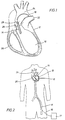
- the blood pump of the invention is shown inserted in the left ventricle 10 of the heart 12.
- the blood pump is generally identified by the reference numeral 14 and is carried at the forward end of a catheter 16.
- Access to the heart 12 is provided in the preferred embodiment through the femoral artery 18. This is the preferred insertion point, however, it is understood that the heart 12 may be accessed through other arteries or other surgical means.
- the blood pump 14 is located in the left ventricle 10. However, in some circumstances it may be desirable to locate the blood pump 14 in the right ventricle 20. Access to the right ventricle 20 may be provided through the pulmonary artery 22. In operation, the intake end of the blood pump 14 shown in Fig.
- the outlet or discharge end of the blood pump 14 is located in the aorta 24.
- the blood pump 14 thus extends partially into the left ventricle 10 through the heart valve 26. Blood is pumped through the blood pump 14 from the left ventricle 10 in the direction of the arrows 28 into the aorta 24.
- the pump 14 is provided with a suction tube 15 mounted to the intake end of the pump 14.
- the suction tube 15 is formed of a flexible, elastomeric material and projects from the intake end of the pump 14 into the left ventricle 10 of the heart 12 as shown in Fig. 6.
- the pump 14 is shown in greater detail.
- the pump 14 is driven by a flexible drive shaft 30 which extends through the catheter 16.
- the drive shaft 30 is driven by a motor 31 located outside the patient's body, as best shown in Fig. 2.
- the pump 14 is secured to the distal end of the catheter 16.
- the pump 14 and catheter 16 are guided through the femoral artery to the left ventricle 10.
- the pump 14 is positioned in the left ventricle 10 of the heart.
- the pump 14 is positioned so that the intake end 32 extends through the heart valve 26 into the left ventricle 10.
- the discharge end 34 of the pump 14 is positioned outside the left ventricle 10 so that pumped blood is discharged into the aorta 24 as shown in Fig. 1.
- the pump 14 comprises a substantially cylindrical elongate body 36.
- the intake end 32 of the body 36 presents a cone-like profile blunted at its forward end so that it may easily be inserted into the left ventricle 10 past the heart valve 26 without damaging the heart valve or any of the heart tissue.
- the intake end 32 includes a number of intake ports 38 so that blood collected in the left ventricle 10 may flow freely into the pump 14.
- Housed within the housing 36 is a stator 40 and a rotor 42.
- the stator and rotor operate utilizing the moineau pumping principal which uses rotary motion to move a seal continuously through the stator 40 for pumping blood through the pump 14.
- the stator 40 is fabricated of resilient material and the rotor 42 is fabricated of stainless steel material formed in a helical shape.
- the rotor 42 is connected to the drive shaft 30 by a flexible joint 44 which permits the end of the rotor 42 to move through a helical path as the rotor 42 is driven by the drive shaft 30.
- a discharge nozzle 46 is provided for directing the pumped blood to the intake end 50 of a venturi tube 48. It will be observed that the discharge end of the discharge nozzle 46 extends into the intake end 50 of the venturi tube 48. An annular space 52 is thus defined between the discharge end 49 of the discharge nozzle 46 and the intake end 50 of the venturi tube 48.
- the intake end 50 of the venturi tube 48 is open to a chamber 54 formed within the housing 36 about the discharge nozzle 46 and venturi tube 48. Blood collected in the left ventricle 10 enters the chamber 54 through a plurality of ports 56.
- blood from the left ventricle 10, in the embodiment of Fig. 3, is sucked through the intake 32 and pumped into the discharge nozzle 46 by rotation of the rotor 42.
- the blood is pressurized as it is pumped through the discharge nozzle 46 by restricting the discharge area of the discharge nozzle 46 and thereby jetting the blood into the venturi tube 48.
- the restriction in the discharge nozzle 46 and venturi tube 48 are designed to cause the pumped blood passing through the discharge nozzle 48 to attain venturi velocities which can be precisely determined.
- venturi velocities negative pressure is produced in the annular space 52 around the discharge end 49 of the discharge nozzle 46.
- FIG. 4 an alternate embodiment of the pump of the invention generally identified by the reference numeral 60 is shown.
- the pump 60 utilizes the same moineau type pumping principal to move blood through the pump, however, the stator and rotor are modified somewhat as will be described in grater detail.
- the pump 60 is positioned in the left ventricle 10 of the heart 12 by the catheter 16 in the same manner as previously described with regard to pump 14.
- the pump 60 is very similar to the pump 14 and therefore like reference numerals are used to indicate like elements.
- the stator 62 of the pump 60 is provided with multiple suction intake ports which discharge into a common discharge duct.
- the stator 62 is fabricated of a resilient material and includes three intake ports 64, 66 and 68.
- the intake port 64 is located at the forward end of the stator 64.
- the intake ports 66 and 68 are located on the cylindrical body of the stator 62 and are formed by drilling a hole at an angle through the body 62 opening into a rotor cavity.
- Each of the intake ports 64, 66 and 68 communicate with separate rotor cavities 70, 72 and 74, respectively, which form the rotor cavity of the pump 60.
- the rotor cavities 70, 72 and 74 include outlet ports 76, 78 and 80 which discharge into a common discharge duct 82.
- the rotor cavities 70, 72 and 74 are separated by shaft stabilizers 84 which support and seal about the rotor 86 within the rotor cavity of the pump 60.
- the rotor 86 is driven by drive shaft 88 which is connected to the drive motor 31.
- the drive shaft 88 is connected to the rotor 86 by a flexible joint 90 which permits the end of the rotor 86 to move through a slight orbital path as the rotor 86 is rotated by the drive shaft 88.
- the pump 60 shown in Fig. 4 permits multistage pumping by a single rotor and stator so that a greater volume of blood is pumped through the pump 60 with each revolution of the rotor 86.
- the rotor cavities 70, 72 and 74 are configured for separate and individual pumping upon rotation of the rotor 86.
- rotation of the rotor 86 by the drive shaft 88 moves a seal continuously through each of the cavities 70, 72 and 74.
- blood enters the rotor cavities 70, 72 and 74 through the intake ports 64, 66 and 68.
- Each rotation of the rotor 86 sweeps the rotor cavities 70, 72 and 74 and forces the blood through the outlet ports 76, 78 and 80 into the common discharge duct 82 and then into the conduit 92 which discharges into the aorta 24 through outlet ports 93.
- the single stage pump 100 is substantially identical to the multistage pump 60 show in Fig. 4. It is placed in the left ventricle 10 of the heart 12 in substantially the same manner as previously described.
- the single stage pump 100 comprises a stator 102 which houses a rotor 104.
- the stator 102 is fabricated of resilient material so that a rotating seal is formed with the helical shaped stainless steel rotor 104.
- the stator 102 includes a helical rotor cavity 101 having an intake port 106 and an outlet port 108.
- the rotor 104 is connected to a drive shaft 110 by a flexible joint 112.
- the drive shaft 110 is centrally positioned within the discharge conduit 114 of the pump 100 by a shaft stabilizer 116.
- the single stage pump 100 draws blood from the left ventricle 10 through the intake port 106.
- a moving seal is formed with the stator 102 so that blood is pumped through the helical cavity 102 and discharged into the conduit 114.
- the shaft stabilizer 116 includes a plurality of apertures 118 extending therethrough permitting blood to flow past the shaft stabilizer 116 to be discharged into the aorta 24 through outlet ports 120 located in the rear wall of the the pump 100.
- the heart assist pump of the present invention utilizes the geometrical relationship between the rotor and the stator to pump blood from the heart of a patient.
- the rotor and stator are in contact with each other at two points which form two sealing lines over the length of the rotor and stator.
- the rotor has a single helix shape and is typically fabricated of a metallic material.
- the stator is formed as a double helix and is typically fabricated of an elastomer. The interference or compression fit between the rotor and stator creates a series of sealed chambers or cavities. Pumping action is achieved by the rotor driven eccentrically within the stator.
- Fluid such as blood
- the cavity formed at the inlet end of the pump and progresses within the cavity and is discharged through the outlet end. Because the force generating sections of the rotor and stator are smooth and curved, very little surface area is available for contact stress. In cross-section, the stator is obround while the rotor in cross-section is circular. The dissimilarity of the shapes between the rotor and stator creates wedge-shaped cavities within the pump unit. Rotation exerts a progressive displacement of the wedge-shaped cavities. In doing so, blood seeks an exit without turbulence. Thus, the volume of blood flowing through the pump of the invention is directly proportional to rotor speed.
- Blood contained in the sealed cavities which are formed as the rotor turns is displaced axially and with complete continuity from the suction or inlet end to the outlet end of the pump. Despite the fact that the rotor rotates, no turbulence is produced.
- the constant volume of the enclosed cavities eliminates pressurizing forces and thus a low surge pumping action is accomplished which is ideal for shear sensitive materials.
- the pump of the present disclosure is self-priming and non-cavitating.
- the prime creates the suction movement of material without which the material cannot be moved.
- a progressive cavity pump of the type disclosed herein is always in prime.
- Impeller pumps however, loose prime and over-accelerate. Over-acceleration can produce cavitation within the pump, resulting in pockets of partial vacuums in the blood flow, causing the separation of blood parts.
- Blood being a non-Newtonian fluid, is more susceptible to such spontaneous, non-linear viscoelastic behavior. In viscometric fluid motion, each fluid element is undergoing a steady sheering motion. However, in non-linear viscoelastic responses, the symmetry of a simple flow is replaced by functional stress factors and turbulence with loss of efficiencies. More simply stated, the heart assist pump of the present disclosure maintains a non-turbulent, constant volume of blood in the enclosed cavities with no pressurizing forces. The low surge action of the pump disclosed herein produces an ideal flow with very predictable Newtonian flow
- the pump of the present invention is dimensioned to provide blood flow of three to four liters per minute, yet it operates at a speed of approximately 2,500 rpm to produce the required blood flow to sustain a patient while the patient's heart is resting and repairing itself.
- the pump of the present disclosure does not utilize propellers or turbine blades to pump blood.
- the moineau type pump of the present invention substantially reduces or eliminates the risk of hemolysis.
- the blood is pumped through the pump of the invention by a rotating seal formed between the stator and helical rotor as described above. The blood is thus pushed through the stator cavity with each rotation of the rotor. No shear forces are developed that would damage the blood cells as the blood is pumped through the pump and discharged into the aorta of the patient.
Landscapes
- Health & Medical Sciences (AREA)
- Engineering & Computer Science (AREA)
- Heart & Thoracic Surgery (AREA)
- Mechanical Engineering (AREA)
- Hematology (AREA)
- Cardiology (AREA)
- Anesthesiology (AREA)
- Biomedical Technology (AREA)
- Life Sciences & Earth Sciences (AREA)
- Animal Behavior & Ethology (AREA)
- General Health & Medical Sciences (AREA)
- Public Health (AREA)
- Veterinary Medicine (AREA)
- General Engineering & Computer Science (AREA)
- Vascular Medicine (AREA)
- External Artificial Organs (AREA)
- Apparatus For Radiation Diagnosis (AREA)
Claims (10)
- Pompe d'assistance circulatoire temporaire, comprenant:(a) un carter cylindrique allongé (36) ayant au moins un orifice d'admission (38) et au moins un orifice de refoulement (58), ledit carter (36) ayant des dimensions permettant de le faire passer par un vaisseau sanguin humain (18) et de l'introduire dans un coeur (12);(b) un moyen formant pompe (14), comportant un stator (40) et un rotor (42), à l'intérieur dudit carter pour aider le coeur d'un patient à pomper du sang;(c) ledit carter (36) comportant un moyen de refoulement (34) pour refouler du sang dans le système vasculaire du patient;(d) un moyen extravasculaire (31) d'alimentation en énergie relié audit moyen formant pompe (14) pour entraîner ledit rotor (42); et(e) un moyen formant arbre d'entraînement (30) reliant ledit moyen formant pompe (14) audit moyen (31) d'alimentation en énergie;caractérisée en ce que ledit moyen formant pompe est un moyen formant pompe du type Moineau, ledit rotor (42) ayant une forme en hélice simple, le mouvement de révolution du rotor (42) entraînant, d'une manière continue à travers le stator (40), un joint d'étanchéité rotatif formé par contact entre le stator et le rotor hélicoïdal, pour pomper du sang à travers le stator; et ledit moyen formant arbre d'entraînement (30) est relié audit rotor (42) par un joint flexible (44) permettant audit rotor (42) de se déplacer selon une trajectoire orbitale lors de la rotation dudit rotor (42) sous l'action dudit moyen (31) d'alimentation en énergie;
- Pompe selon la revendication 1, comportant une buse de refoulement (46) supportée à l'intérieur dudit carter (36) dans l'alignement dudit stator (40), ladite buse de refoulement (46) comportant un étranglement pour mettre sous pression et propulser du sang pompé à travers elle.
- Pompe selon la revendication 2, comportant un venturi (48) situé à l'intérieur dudit carter (36) dans l'alignement de ladite buse de refoulement (46), ledit venturi (48) coopérant avec ladite buse de refoulement (46) pour former dans ledit carter (36) une zone en dépression.
- Pompe selon la revendication 3, dans laquelle ledit carter (36) comporte une chambre d'aspiration (54) formée autour d'une partie de ladite buse de refoulement (46) et dudit venturi (48), ladite chambre d'aspiration (54) permettant une communication de fluide avec ladite zone en dépression, ladite chambre d'aspiration (54) comportant en outre au moins un orifice d'admission (56) permettant à du sang d'entrer dans ladite chambre d'aspiration (54).
- Pompe selon la revendication 4, dans laquelle le sang recueilli dans ladite chambre d'aspiration (54) est contraint à traverser ledit venturi (48) par l'aspiration créée dans la zone en dépression autour de l'extrémité de refoulement de ladite buse de refoulement (46).
- Pompe selon l'une quelconque des revendications précédentes, dans laquelle ledit moyen formant pompe (14, 60) comporte au moins deux orifices d'admission séparés (64, 66, 68) en communication de fluide avec des cavités séparées (70, 72, 74) de rotor formées dans ledit moyen formant pompe (14, 60), et dans laquelle lesdites cavités séparées (70, 72, 74) comportent des orifices de sortie séparés (76, 78, 80) en communication de fluide avec un conduit de refoulement commun (82).
- Pompe selon la revendication 6, dans laquelle lesdites cavités séparées (70, 72, 74) de rotor sont séparées par au moins un stabilisateur (84) d'arbre supportant ledit rotor (86) à l'intérieur dudit stator (62).
- Pompe selon l'une quelconque des revendications précédentes, dans laquelle ledit stator (40) est en matière élastique et ledit rotor (42) est en acier inoxydable et peut tourner à l'intérieur dudit stator (40).
- Pompe selon l'une quelconque des revendications précédentes, comportant un tuyau d'aspiration (15) dépassant vers l'avant dudit carter cylindrique (36) pour être introduit dans le coeur, ledit tuyau d'aspiration (15) constituant un passage pour la circulation de sang vers ledit moyen formant pompe (14).
- Pompe selon l'une quelconque des revendications précédentes, dans laquelle ledit carter cylindrique (36) portant ledit moyen formant pompe (14) est monté à l'extrémité distale d'un cathéter (16) et guidé jusqu'au coeur d'un patient par ledit cathéter (16).
Priority Applications (2)
| Application Number | Priority Date | Filing Date | Title |
|---|---|---|---|
| DE69027029T DE69027029T2 (de) | 1988-09-27 | 1990-10-09 | Herzunterstützungspumpe |
| AT90311063T ATE137980T1 (de) | 1988-09-27 | 1990-10-09 | Herzunterstützungspumpe |
Applications Claiming Priority (1)
| Application Number | Priority Date | Filing Date | Title |
|---|---|---|---|
| US07/249,830 US4964864A (en) | 1988-09-27 | 1988-09-27 | Heart assist pump |
Publications (2)
| Publication Number | Publication Date |
|---|---|
| EP0480101A1 EP0480101A1 (fr) | 1992-04-15 |
| EP0480101B1 true EP0480101B1 (fr) | 1996-05-15 |
Family
ID=22945204
Family Applications (1)
| Application Number | Title | Priority Date | Filing Date |
|---|---|---|---|
| EP90311063A Expired - Lifetime EP0480101B1 (fr) | 1988-09-27 | 1990-10-09 | Pompe d'assistance cardiaque |
Country Status (5)
| Country | Link |
|---|---|
| US (2) | US4964864A (fr) |
| EP (1) | EP0480101B1 (fr) |
| AT (1) | ATE137980T1 (fr) |
| AU (1) | AU641430B2 (fr) |
| DE (1) | DE69027029T2 (fr) |
Cited By (10)
| Publication number | Priority date | Publication date | Assignee | Title |
|---|---|---|---|---|
| US5746709A (en) * | 1996-04-25 | 1998-05-05 | Medtronic, Inc. | Intravascular pump and bypass assembly and method for using the same |
| US5814011A (en) * | 1996-04-25 | 1998-09-29 | Medtronic, Inc. | Active intravascular lung |
| US10722631B2 (en) | 2018-02-01 | 2020-07-28 | Shifamed Holdings, Llc | Intravascular blood pumps and methods of use and manufacture |
| US11185677B2 (en) | 2017-06-07 | 2021-11-30 | Shifamed Holdings, Llc | Intravascular fluid movement devices, systems, and methods of use |
| US11511103B2 (en) | 2017-11-13 | 2022-11-29 | Shifamed Holdings, Llc | Intravascular fluid movement devices, systems, and methods of use |
| US11654275B2 (en) | 2019-07-22 | 2023-05-23 | Shifamed Holdings, Llc | Intravascular blood pumps with struts and methods of use and manufacture |
| US11724089B2 (en) | 2019-09-25 | 2023-08-15 | Shifamed Holdings, Llc | Intravascular blood pump systems and methods of use and control thereof |
| US11964145B2 (en) | 2019-07-12 | 2024-04-23 | Shifamed Holdings, Llc | Intravascular blood pumps and methods of manufacture and use |
| US12102815B2 (en) | 2019-09-25 | 2024-10-01 | Shifamed Holdings, Llc | Catheter blood pumps and collapsible pump housings |
| US12121713B2 (en) | 2019-09-25 | 2024-10-22 | Shifamed Holdings, Llc | Catheter blood pumps and collapsible blood conduits |
Families Citing this family (132)
| Publication number | Priority date | Publication date | Assignee | Title |
|---|---|---|---|---|
| US4964864A (en) * | 1988-09-27 | 1990-10-23 | American Biomed, Inc. | Heart assist pump |
| JPH0636821B2 (ja) * | 1990-03-08 | 1994-05-18 | 健二 山崎 | 体内埋設形の補助人工心臓 |
| US5163910A (en) * | 1990-04-10 | 1992-11-17 | Mayo Foundation For Medical Education And Research | Intracatheter perfusion pump apparatus and method |
| US5092844A (en) * | 1990-04-10 | 1992-03-03 | Mayo Foundation For Medical Education And Research | Intracatheter perfusion pump apparatus and method |
| US5300112A (en) * | 1992-07-14 | 1994-04-05 | Aai Corporation | Articulated heart pump |
| US5376114A (en) * | 1992-10-30 | 1994-12-27 | Jarvik; Robert | Cannula pumps for temporary cardiac support and methods of their application and use |
| US5947892A (en) * | 1993-11-10 | 1999-09-07 | Micromed Technology, Inc. | Rotary blood pump |
| CA2186078C (fr) * | 1995-09-22 | 2006-12-19 | Daniel E. Alesi | Dispositif de support cardiaque |
| DE19535781C2 (de) * | 1995-09-26 | 1999-11-11 | Fraunhofer Ges Forschung | Vorrichtung zur aktiven Strömungsunterstützung von Körperflüssigkeiten |
| US5810836A (en) * | 1996-03-04 | 1998-09-22 | Myocardial Stents, Inc. | Device and method for trans myocardial revascularization (TMR) |
| US6244835B1 (en) | 1996-06-26 | 2001-06-12 | James F. Antaki | Blood pump having a magnetically suspended rotor |
| US6015272A (en) | 1996-06-26 | 2000-01-18 | University Of Pittsburgh | Magnetically suspended miniature fluid pump and method of designing the same |
| US5851174A (en) * | 1996-09-17 | 1998-12-22 | Robert Jarvik | Cardiac support device |
| US5965089A (en) | 1996-10-04 | 1999-10-12 | United States Surgical Corporation | Circulatory support system |
| US6532964B2 (en) * | 1997-07-11 | 2003-03-18 | A-Med Systems, Inc. | Pulmonary and circulatory blood flow support devices and methods for heart surgery procedures |
| US7182727B2 (en) * | 1997-07-11 | 2007-02-27 | A—Med Systems Inc. | Single port cardiac support apparatus |
| US6123725A (en) * | 1997-07-11 | 2000-09-26 | A-Med Systems, Inc. | Single port cardiac support apparatus |
| US6889082B2 (en) | 1997-10-09 | 2005-05-03 | Orqis Medical Corporation | Implantable heart assist system and method of applying same |
| US6007478A (en) * | 1997-11-13 | 1999-12-28 | Impella Cardiotechnik Aktiengesellschaft | Cannula having constant wall thickness with increasing distal flexibility and method of making |
| US6086527A (en) * | 1998-04-02 | 2000-07-11 | Scimed Life Systems, Inc. | System for treating congestive heart failure |
| US7122019B1 (en) | 2000-11-28 | 2006-10-17 | Flowmedica Inc. | Intra-aortic renal drug delivery catheter |
| US7329236B2 (en) | 1999-01-11 | 2008-02-12 | Flowmedica, Inc. | Intra-aortic renal drug delivery catheter |
| US6749598B1 (en) | 1999-01-11 | 2004-06-15 | Flowmedica, Inc. | Apparatus and methods for treating congestive heart disease |
| US7780628B1 (en) | 1999-01-11 | 2010-08-24 | Angiodynamics, Inc. | Apparatus and methods for treating congestive heart disease |
| US7481803B2 (en) | 2000-11-28 | 2009-01-27 | Flowmedica, Inc. | Intra-aortic renal drug delivery catheter |
| US20020128587A1 (en) * | 1999-01-13 | 2002-09-12 | A-Med Systems, Inc. | Pulmonary and circulatory blood flow support devices and methods for heart surgery procedures |
| US6245007B1 (en) * | 1999-01-28 | 2001-06-12 | Terumo Cardiovascular Systems Corporation | Blood pump |
| US7022100B1 (en) | 1999-09-03 | 2006-04-04 | A-Med Systems, Inc. | Guidable intravascular blood pump and related methods |
| US7366754B2 (en) * | 2001-06-29 | 2008-04-29 | Thomson Licensing | Multi-media jitter removal in an asynchronous digital home network |
| CA2374989A1 (fr) * | 2002-03-08 | 2003-09-08 | Andre Garon | Dispositif d'assistance ventriculaire comprenant une pompe a sang hybride a double entree |
| US7029433B2 (en) * | 2002-03-16 | 2006-04-18 | Chang Sheldon S | Device for cardiac restoration |
| US7241257B1 (en) * | 2002-06-28 | 2007-07-10 | Abbott Cardiovascular Systems, Inc. | Devices and methods to perform minimally invasive surgeries |
| US6936222B2 (en) | 2002-09-13 | 2005-08-30 | Kenneth L. Franco | Methods, apparatuses, and applications for compliant membrane blood gas exchangers |
| EP1585572A4 (fr) | 2002-09-20 | 2010-02-24 | Flowmedica Inc | Procede et appareil pour administrer une substance intra-aortique a un vaisseau ramifie |
| US7063679B2 (en) | 2002-09-20 | 2006-06-20 | Flowmedica, Inc. | Intra-aortic renal delivery catheter |
| AU2003276903A1 (en) | 2002-09-20 | 2004-05-04 | Flowmedica, Inc. | Method and apparatus for selective material delivery via an intra-renal catheter |
| US7993325B2 (en) | 2002-09-20 | 2011-08-09 | Angio Dynamics, Inc. | Renal infusion systems and methods |
| JP2006513809A (ja) | 2002-09-20 | 2006-04-27 | フローメディカ,インコーポレイテッド | 送達シースを通して大動脈内カテーテルを挿入するための装置および方法 |
| US20050197624A1 (en) * | 2004-03-04 | 2005-09-08 | Flowmedica, Inc. | Sheath for use in peripheral interventions |
| CA2428741A1 (fr) * | 2003-05-13 | 2004-11-13 | Cardianove Inc. | Pompe a sang helicocentrifuge a double canal d'entree |
| EP1635736A2 (fr) | 2003-06-05 | 2006-03-22 | FlowMedica, Inc. | Systemes et procedes destines a realiser des interventions bilaterales ou un diagnostic dans des lumieres du corps ramifiees |
| US20060167437A1 (en) * | 2003-06-17 | 2006-07-27 | Flowmedica, Inc. | Method and apparatus for intra aortic substance delivery to a branch vessel |
| WO2005016165A1 (fr) * | 2003-08-05 | 2005-02-24 | Flowmedica, Inc. | Systeme et methode de prevention de la nephropathie induite par les produits de contraste radiologique |
| US7494477B2 (en) * | 2003-09-02 | 2009-02-24 | Pulsecath B.V. | Catheter pump, catheter and fittings therefore and methods of using a catheter pump |
| WO2005028872A2 (fr) | 2003-09-18 | 2005-03-31 | Myrakelle, Llc | Pompe a sang rotative |
| JP2007537298A (ja) | 2004-05-14 | 2007-12-20 | フロウメディカ, インコーポレイテッド | うっ血性心不全の処置およびbnp療法のための両側性局所腎臓送達 |
| US7393181B2 (en) | 2004-09-17 | 2008-07-01 | The Penn State Research Foundation | Expandable impeller pump |
| US20060069323A1 (en) * | 2004-09-24 | 2006-03-30 | Flowmedica, Inc. | Systems and methods for bi-lateral guidewire cannulation of branched body lumens |
| WO2007044907A2 (fr) * | 2005-10-11 | 2007-04-19 | Flowmedica, Inc. | Gaine vasculaire à construction de lumière variable |
| CN101448535B (zh) | 2006-03-23 | 2011-10-19 | 宾州研究基金会 | 带有可膨胀叶轮泵的心脏辅助装置 |
| CA2647151A1 (fr) | 2006-03-31 | 2007-10-11 | Orqis Medical Corporation | Pompe sanguine rotative |
| US7771401B2 (en) | 2006-06-08 | 2010-08-10 | Angiodynamics, Inc. | Selective renal cannulation and infusion systems and methods |
| US20080221551A1 (en) * | 2007-03-09 | 2008-09-11 | Flowmedica, Inc. | Acute kidney injury treatment systems and methods |
| US8439859B2 (en) | 2007-10-08 | 2013-05-14 | Ais Gmbh Aachen Innovative Solutions | Catheter device |
| US20090105799A1 (en) * | 2007-10-23 | 2009-04-23 | Flowmedica, Inc. | Renal assessment systems and methods |
| EP2292282B1 (fr) | 2008-06-23 | 2017-11-15 | Thoratec Corporation | Pompe à sang |
| EP3050537A1 (fr) | 2008-10-06 | 2016-08-03 | Indiana University Research and Technology Corporation | Procédés et appareil destinés à une assistance active ou passive dans le système circulatoire |
| US9067005B2 (en) | 2008-12-08 | 2015-06-30 | Thoratec Corporation | Centrifugal pump apparatus |
| JP5378010B2 (ja) | 2009-03-05 | 2013-12-25 | ソラテック コーポレーション | 遠心式ポンプ装置 |
| CN102341600B (zh) | 2009-03-06 | 2014-12-10 | 胸腔科技有限公司 | 离心式泵装置 |
| EP2246078A1 (fr) * | 2009-04-29 | 2010-11-03 | ECP Entwicklungsgesellschaft mbH | Agencement d'arbres doté d'un arbre se déroulant à l'intérieur d'une enveloppe rempli de fluide |
| CA2769631A1 (fr) | 2009-07-01 | 2011-01-06 | The Penn State Research Foundation | Pompe pour le sang pourvue d'une canule extensible |
| JP5656835B2 (ja) | 2009-07-29 | 2015-01-21 | ソーラテック コーポレイション | 回転駆動装置およびそれを用いた遠心式ポンプ装置 |
| US8690749B1 (en) | 2009-11-02 | 2014-04-08 | Anthony Nunez | Wireless compressible heart pump |
| JP5443197B2 (ja) | 2010-02-16 | 2014-03-19 | ソラテック コーポレーション | 遠心式ポンプ装置 |
| EP2554191B1 (fr) | 2010-03-26 | 2019-05-08 | Thoratec Corporation | Dispositif de pompe sanguine centrifuge |
| EP2388029A1 (fr) * | 2010-05-17 | 2011-11-23 | ECP Entwicklungsgesellschaft mbH | Agencement de pompe |
| JP5681403B2 (ja) | 2010-07-12 | 2015-03-11 | ソーラテック コーポレイション | 遠心式ポンプ装置 |
| JP5577506B2 (ja) | 2010-09-14 | 2014-08-27 | ソーラテック コーポレイション | 遠心式ポンプ装置 |
| US8485961B2 (en) | 2011-01-05 | 2013-07-16 | Thoratec Corporation | Impeller housing for percutaneous heart pump |
| US8597170B2 (en) | 2011-01-05 | 2013-12-03 | Thoratec Corporation | Catheter pump |
| WO2012094535A2 (fr) | 2011-01-06 | 2012-07-12 | Thoratec Corporation | Pompe cardiaque percutanée |
| WO2012094641A2 (fr) | 2011-01-06 | 2012-07-12 | Thoratec Corporation | Pompe cardiaque percutanée |
| EP2693609B1 (fr) | 2011-03-28 | 2017-05-03 | Thoratec Corporation | Dispositif de rotation et d'entraînement, et dispositif de pompe centrifuge utilisant ce dispositif |
| EP2707053B1 (fr) | 2011-05-13 | 2016-11-30 | Heartware, Inc. | Pompe à sang vasculaire et procédé d'implantation |
| JP6083929B2 (ja) | 2012-01-18 | 2017-02-22 | ソーラテック コーポレイション | 遠心式ポンプ装置 |
| WO2013116610A1 (fr) * | 2012-02-01 | 2013-08-08 | St. Jude Medical, Cardiology Division, Inc. | Appareil de réparation de valve cardiaque |
| US9446179B2 (en) | 2012-05-14 | 2016-09-20 | Thoratec Corporation | Distal bearing support |
| US9872947B2 (en) | 2012-05-14 | 2018-01-23 | Tc1 Llc | Sheath system for catheter pump |
| US9327067B2 (en) | 2012-05-14 | 2016-05-03 | Thoratec Corporation | Impeller for catheter pump |
| US8721517B2 (en) | 2012-05-14 | 2014-05-13 | Thoratec Corporation | Impeller for catheter pump |
| DE102013008168A1 (de) | 2012-05-14 | 2013-11-14 | Thoratec Corporation | Laufrad für Katheterpumpe |
| US9421311B2 (en) | 2012-07-03 | 2016-08-23 | Thoratec Corporation | Motor assembly for catheter pump |
| EP4186557A1 (fr) | 2012-07-03 | 2023-05-31 | Tc1 Llc | Ensemble motour pour pompe à cathéter |
| US9358329B2 (en) | 2012-07-03 | 2016-06-07 | Thoratec Corporation | Catheter pump |
| US9371826B2 (en) | 2013-01-24 | 2016-06-21 | Thoratec Corporation | Impeller position compensation using field oriented control |
| US9556873B2 (en) | 2013-02-27 | 2017-01-31 | Tc1 Llc | Startup sequence for centrifugal pump with levitated impeller |
| EP2968718B1 (fr) | 2013-03-13 | 2021-04-21 | Tc1 Llc | Système de traitement de fluide |
| US11033728B2 (en) | 2013-03-13 | 2021-06-15 | Tc1 Llc | Fluid handling system |
| US11077294B2 (en) | 2013-03-13 | 2021-08-03 | Tc1 Llc | Sheath assembly for catheter pump |
| US9308302B2 (en) | 2013-03-15 | 2016-04-12 | Thoratec Corporation | Catheter pump assembly including a stator |
| EP3797810A1 (fr) | 2013-03-15 | 2021-03-31 | Tc1 Llc | Ensemble pompe de cathéter comprenant un stator |
| US9713663B2 (en) | 2013-04-30 | 2017-07-25 | Tc1 Llc | Cardiac pump with speed adapted for ventricle unloading |
| US10052420B2 (en) | 2013-04-30 | 2018-08-21 | Tc1 Llc | Heart beat identification and pump speed synchronization |
| WO2015160990A1 (fr) | 2014-04-15 | 2015-10-22 | Thoratec Corporation | Systèmes et procédés d'introduction de pompe de cathéter |
| US10029037B2 (en) | 2014-04-15 | 2018-07-24 | Tc1 Llc | Sensors for catheter pumps |
| EP3479854A1 (fr) | 2014-04-15 | 2019-05-08 | Tc1 Llc | Pompe de cathéter ayant des orifices d'accès |
| US10583232B2 (en) | 2014-04-15 | 2020-03-10 | Tc1 Llc | Catheter pump with off-set motor position |
| DE102014211216A1 (de) * | 2014-06-12 | 2015-12-17 | Universität Duisburg-Essen | Pumpe zur Implantierung in ein Gefäß |
| US10449279B2 (en) | 2014-08-18 | 2019-10-22 | Tc1 Llc | Guide features for percutaneous catheter pump |
| US9623161B2 (en) | 2014-08-26 | 2017-04-18 | Tc1 Llc | Blood pump and method of suction detection |
| EP3247421B1 (fr) | 2015-01-22 | 2019-10-02 | Tc1 Llc | Ensemble moteur avec échangeur de chaleur pour pompe de cathéter |
| EP3247420B1 (fr) | 2015-01-22 | 2019-10-02 | Tc1 Llc | Ensemble moteur à masse de rotation réduite pour pompe pour cathéter |
| US9675738B2 (en) | 2015-01-22 | 2017-06-13 | Tc1 Llc | Attachment mechanisms for motor of catheter pump |
| WO2016130846A1 (fr) | 2015-02-11 | 2016-08-18 | Thoratec Corporation | Identification de battement cardiaque et synchronisation de vitesse de pompe |
| WO2016130944A1 (fr) | 2015-02-12 | 2016-08-18 | Thoratec Corporation | Système et procédé de commande de la position d'un rotor en lévitation |
| US10371152B2 (en) | 2015-02-12 | 2019-08-06 | Tc1 Llc | Alternating pump gaps |
| US10245361B2 (en) | 2015-02-13 | 2019-04-02 | Tc1 Llc | Impeller suspension mechanism for heart pump |
| US9907890B2 (en) | 2015-04-16 | 2018-03-06 | Tc1 Llc | Catheter pump with positioning brace |
| US10117983B2 (en) | 2015-11-16 | 2018-11-06 | Tc1 Llc | Pressure/flow characteristic modification of a centrifugal pump in a ventricular assist device |
| EP3487549B1 (fr) | 2016-07-21 | 2021-02-24 | Tc1 Llc | Joints fluidiques pour ensemble de moteur de pompe à cathéter |
| EP3487550B1 (fr) | 2016-07-21 | 2022-09-28 | Tc1 Llc | Chambre remplie de gaz pour ensemble moteur-pompe de cathéter |
| CA3039285A1 (fr) | 2016-10-25 | 2018-05-03 | Magenta Medical Ltd. | Dispositif d'assistance ventriculaire |
| US10905808B2 (en) | 2018-01-10 | 2021-02-02 | Magenta Medical Ltd. | Drive cable for use with a blood pump |
| CN115089870A (zh) | 2018-01-10 | 2022-09-23 | 马真塔医药有限公司 | 心室辅助装置 |
| DE102018201030A1 (de) | 2018-01-24 | 2019-07-25 | Kardion Gmbh | Magnetkuppelelement mit magnetischer Lagerungsfunktion |
| WO2020198765A2 (fr) | 2019-03-26 | 2020-10-01 | Puzzle Medical Devices Inc. | Dispositif modulaire, implantable dans le corps d'un mammifère, agissant sur un flux de fluide, et procédés associés |
| US11690997B2 (en) | 2018-04-06 | 2023-07-04 | Puzzle Medical Devices Inc. | Mammalian body conduit intralumenal device and lumen wall anchor assembly, components thereof and methods of implantation and explanation thereof |
| US11110264B2 (en) | 2018-04-20 | 2021-09-07 | Cardiovascular Systems, Inc. | Intravascular pump with expandable distal region |
| US11020582B2 (en) | 2018-04-20 | 2021-06-01 | Cardiovascular Systems, Inc. | Intravascular pump with expandable region |
| US11167121B2 (en) | 2018-05-15 | 2021-11-09 | Cardiovascular Systems, Inc. | Intravascular pump with integrated isolated conductor(s) and methods thereof |
| DE102018207611A1 (de) | 2018-05-16 | 2019-11-21 | Kardion Gmbh | Rotorlagerungssystem |
| DE102018207575A1 (de) | 2018-05-16 | 2019-11-21 | Kardion Gmbh | Magnetische Stirndreh-Kupplung zur Übertragung von Drehmomenten |
| DE102018208541A1 (de) | 2018-05-30 | 2019-12-05 | Kardion Gmbh | Axialpumpe für ein Herzunterstützungssystem und Verfahren zum Herstellen einer Axialpumpe für ein Herzunterstützungssystem |
| DE102018211327A1 (de) | 2018-07-10 | 2020-01-16 | Kardion Gmbh | Laufrad für ein implantierbares, vaskuläres Unterstützungssystem |
| DE102018212153A1 (de) | 2018-07-20 | 2020-01-23 | Kardion Gmbh | Zulaufleitung für eine Pumpeneinheit eines Herzunterstützungssystems, Herzunterstützungssystem und Verfahren zum Herstellen einer Zulaufleitung für eine Pumpeneinheit eines Herzunterstützungssystems |
| US11013904B2 (en) | 2018-07-30 | 2021-05-25 | Cardiovascular Systems, Inc. | Intravascular pump with proximal and distal pressure or flow sensors and distal sensor tracking |
| US11202900B2 (en) | 2018-07-31 | 2021-12-21 | Cardiovascular Systems, Inc. | Intravascular pump with controls and display screen on handle |
| EP3782668B1 (fr) | 2019-01-24 | 2021-08-11 | Magenta Medical Ltd. | Boitier pour un impulseur |
| DE102020102474A1 (de) | 2020-01-31 | 2021-08-05 | Kardion Gmbh | Pumpe zum Fördern eines Fluids und Verfahren zum Herstellen einer Pumpe |
| CN114746142A (zh) | 2020-04-07 | 2022-07-12 | 马真塔医药有限公司 | 心室辅助装置 |
| WO2023168336A2 (fr) * | 2022-03-02 | 2023-09-07 | Xtract Medical, Inc. | Dispositifs et procédés d'élimination de matière d'un patient |
Family Cites Families (17)
| Publication number | Priority date | Publication date | Assignee | Title |
|---|---|---|---|---|
| GB628203A (en) * | 1947-09-04 | 1949-08-24 | Fmc Corp | Improvements in meshing-screw pumps |
| US3479960A (en) * | 1966-12-26 | 1969-11-25 | Magnesita Sa | Encased electric pump |
| US3505987A (en) * | 1967-03-17 | 1970-04-14 | Medrad Inc | Intra-aortic heart pump |
| US3667069A (en) * | 1970-03-27 | 1972-06-06 | Univ Minnesota | Jet pump cardiac replacement and assist device and method of at least partially replacing a disabled right heart |
| DE2453296A1 (de) * | 1974-11-11 | 1976-05-13 | Dieter Von Zeppelin | Pumpvorrichtung fuer medizinische zwecke |
| US4051840A (en) * | 1976-01-05 | 1977-10-04 | Sinai Hospital Of Detroit | Dynamic aortic patch |
| US4102610A (en) * | 1976-09-03 | 1978-07-25 | John Taboada | Constant volume seal-free reciprocating pump |
| US4173796A (en) * | 1977-12-09 | 1979-11-13 | University Of Utah | Total artificial hearts and cardiac assist devices powered and controlled by reversible electrohydraulic energy converters |
| US4382199A (en) * | 1980-11-06 | 1983-05-03 | Nu-Tech Industries, Inc. | Hydrodynamic bearing system for a brushless DC motor |
| US4625712A (en) * | 1983-09-28 | 1986-12-02 | Nimbus, Inc. | High-capacity intravascular blood pump utilizing percutaneous access |
| US4676725A (en) * | 1985-12-27 | 1987-06-30 | Hughes Tool Company | Moineau type gear mechanism with resilient sleeve |
| US4817586A (en) * | 1987-11-24 | 1989-04-04 | Nimbus Medical, Inc. | Percutaneous bloom pump with mixed-flow output |
| US4846152A (en) * | 1987-11-24 | 1989-07-11 | Nimbus Medical, Inc. | Single-stage axial flow blood pump |
| US4964864A (en) * | 1988-09-27 | 1990-10-23 | American Biomed, Inc. | Heart assist pump |
| US4957504A (en) * | 1988-12-02 | 1990-09-18 | Chardack William M | Implantable blood pump |
| US4969865A (en) * | 1989-01-09 | 1990-11-13 | American Biomed, Inc. | Helifoil pump |
| US4944722A (en) * | 1989-02-23 | 1990-07-31 | Nimbus Medical, Inc. | Percutaneous axial flow blood pump |
-
1988
- 1988-09-27 US US07/249,830 patent/US4964864A/en not_active Expired - Fee Related
-
1990
- 1990-10-02 AU AU63699/90A patent/AU641430B2/en not_active Ceased
- 1990-10-09 EP EP90311063A patent/EP0480101B1/fr not_active Expired - Lifetime
- 1990-10-09 DE DE69027029T patent/DE69027029T2/de not_active Expired - Fee Related
- 1990-10-09 AT AT90311063T patent/ATE137980T1/de not_active IP Right Cessation
- 1990-10-22 US US07/601,881 patent/US5112349A/en not_active Expired - Fee Related
Cited By (13)
| Publication number | Priority date | Publication date | Assignee | Title |
|---|---|---|---|---|
| US5746709A (en) * | 1996-04-25 | 1998-05-05 | Medtronic, Inc. | Intravascular pump and bypass assembly and method for using the same |
| US5814011A (en) * | 1996-04-25 | 1998-09-29 | Medtronic, Inc. | Active intravascular lung |
| US11185677B2 (en) | 2017-06-07 | 2021-11-30 | Shifamed Holdings, Llc | Intravascular fluid movement devices, systems, and methods of use |
| US11717670B2 (en) | 2017-06-07 | 2023-08-08 | Shifamed Holdings, LLP | Intravascular fluid movement devices, systems, and methods of use |
| US11511103B2 (en) | 2017-11-13 | 2022-11-29 | Shifamed Holdings, Llc | Intravascular fluid movement devices, systems, and methods of use |
| US10722631B2 (en) | 2018-02-01 | 2020-07-28 | Shifamed Holdings, Llc | Intravascular blood pumps and methods of use and manufacture |
| US11229784B2 (en) | 2018-02-01 | 2022-01-25 | Shifamed Holdings, Llc | Intravascular blood pumps and methods of use and manufacture |
| US12076545B2 (en) | 2018-02-01 | 2024-09-03 | Shifamed Holdings, Llc | Intravascular blood pumps and methods of use and manufacture |
| US11964145B2 (en) | 2019-07-12 | 2024-04-23 | Shifamed Holdings, Llc | Intravascular blood pumps and methods of manufacture and use |
| US11654275B2 (en) | 2019-07-22 | 2023-05-23 | Shifamed Holdings, Llc | Intravascular blood pumps with struts and methods of use and manufacture |
| US11724089B2 (en) | 2019-09-25 | 2023-08-15 | Shifamed Holdings, Llc | Intravascular blood pump systems and methods of use and control thereof |
| US12102815B2 (en) | 2019-09-25 | 2024-10-01 | Shifamed Holdings, Llc | Catheter blood pumps and collapsible pump housings |
| US12121713B2 (en) | 2019-09-25 | 2024-10-22 | Shifamed Holdings, Llc | Catheter blood pumps and collapsible blood conduits |
Also Published As
| Publication number | Publication date |
|---|---|
| DE69027029T2 (de) | 1997-01-23 |
| EP0480101A1 (fr) | 1992-04-15 |
| DE69027029D1 (de) | 1996-06-20 |
| AU641430B2 (en) | 1993-09-23 |
| AU6369990A (en) | 1992-06-11 |
| US4964864A (en) | 1990-10-23 |
| US5112349A (en) | 1992-05-12 |
| ATE137980T1 (de) | 1996-06-15 |
Similar Documents
| Publication | Publication Date | Title |
|---|---|---|
| EP0480101B1 (fr) | Pompe d'assistance cardiaque | |
| US5112292A (en) | Helifoil pump | |
| US4969865A (en) | Helifoil pump | |
| US10874783B2 (en) | Catheter device | |
| US20220134082A1 (en) | Catheter device | |
| CA3020247C (fr) | Mecanisme de catheter | |
| CA2927346C (fr) | Mecanisme de catheter | |
| US5222980A (en) | Implantable heart-assist device | |
| JPH11511370A (ja) | 体液の流れを積極的に助成するためのシステム | |
| JPH04176471A (ja) | 循環補助ポンプ | |
| CA2026692A1 (fr) | Pompe de soutien cardiaque | |
| CA2026693A1 (fr) | Pompe helicoidale | |
| JPH04156856A (ja) | 循環補助ポンプ |
Legal Events
| Date | Code | Title | Description |
|---|---|---|---|
| PUAI | Public reference made under article 153(3) epc to a published international application that has entered the european phase |
Free format text: ORIGINAL CODE: 0009012 |
|
| AK | Designated contracting states |
Kind code of ref document: A1 Designated state(s): AT BE CH DE DK ES FR GB GR IT LI LU NL SE |
|
| 17P | Request for examination filed |
Effective date: 19921007 |
|
| 17Q | First examination report despatched |
Effective date: 19940509 |
|
| GRAH | Despatch of communication of intention to grant a patent |
Free format text: ORIGINAL CODE: EPIDOS IGRA |
|
| GRAA | (expected) grant |
Free format text: ORIGINAL CODE: 0009210 |
|
| AK | Designated contracting states |
Kind code of ref document: B1 Designated state(s): AT BE CH DE DK ES FR GB GR IT LI LU NL SE |
|
| PG25 | Lapsed in a contracting state [announced via postgrant information from national office to epo] |
Ref country code: NL Free format text: LAPSE BECAUSE OF FAILURE TO SUBMIT A TRANSLATION OF THE DESCRIPTION OR TO PAY THE FEE WITHIN THE PRESCRIBED TIME-LIMIT Effective date: 19960515 Ref country code: LI Effective date: 19960515 Ref country code: GR Free format text: LAPSE BECAUSE OF FAILURE TO SUBMIT A TRANSLATION OF THE DESCRIPTION OR TO PAY THE FEE WITHIN THE PRESCRIBED TIME-LIMIT Effective date: 19960515 Ref country code: ES Free format text: THE PATENT HAS BEEN ANNULLED BY A DECISION OF A NATIONAL AUTHORITY Effective date: 19960515 Ref country code: DK Effective date: 19960515 Ref country code: CH Effective date: 19960515 Ref country code: BE Effective date: 19960515 Ref country code: AT Effective date: 19960515 |
|
| REF | Corresponds to: |
Ref document number: 137980 Country of ref document: AT Date of ref document: 19960615 Kind code of ref document: T |
|
| REF | Corresponds to: |
Ref document number: 69027029 Country of ref document: DE Date of ref document: 19960620 |
|
| ITF | It: translation for a ep patent filed | ||
| PG25 | Lapsed in a contracting state [announced via postgrant information from national office to epo] |
Ref country code: SE Effective date: 19960815 |
|
| ET | Fr: translation filed | ||
| PG25 | Lapsed in a contracting state [announced via postgrant information from national office to epo] |
Ref country code: LU Free format text: LAPSE BECAUSE OF NON-PAYMENT OF DUE FEES Effective date: 19961031 |
|
| NLV1 | Nl: lapsed or annulled due to failure to fulfill the requirements of art. 29p and 29m of the patents act | ||
| REG | Reference to a national code |
Ref country code: CH Ref legal event code: PL |
|
| PLBE | No opposition filed within time limit |
Free format text: ORIGINAL CODE: 0009261 |
|
| STAA | Information on the status of an ep patent application or granted ep patent |
Free format text: STATUS: NO OPPOSITION FILED WITHIN TIME LIMIT |
|
| 26N | No opposition filed | ||
| PGFP | Annual fee paid to national office [announced via postgrant information from national office to epo] |
Ref country code: GB Payment date: 19970930 Year of fee payment: 8 |
|
| PGFP | Annual fee paid to national office [announced via postgrant information from national office to epo] |
Ref country code: DE Payment date: 19971017 Year of fee payment: 8 |
|
| PG25 | Lapsed in a contracting state [announced via postgrant information from national office to epo] |
Ref country code: GB Free format text: LAPSE BECAUSE OF NON-PAYMENT OF DUE FEES Effective date: 19981009 |
|
| PGFP | Annual fee paid to national office [announced via postgrant information from national office to epo] |
Ref country code: FR Payment date: 19990430 Year of fee payment: 9 |
|
| GBPC | Gb: european patent ceased through non-payment of renewal fee |
Effective date: 19981009 |
|
| PG25 | Lapsed in a contracting state [announced via postgrant information from national office to epo] |
Ref country code: DE Free format text: LAPSE BECAUSE OF NON-PAYMENT OF DUE FEES Effective date: 19990803 |
|
| PG25 | Lapsed in a contracting state [announced via postgrant information from national office to epo] |
Ref country code: FR Free format text: LAPSE BECAUSE OF NON-PAYMENT OF DUE FEES Effective date: 20000630 |
|
| REG | Reference to a national code |
Ref country code: FR Ref legal event code: ST |
|
| PG25 | Lapsed in a contracting state [announced via postgrant information from national office to epo] |
Ref country code: IT Free format text: LAPSE BECAUSE OF NON-PAYMENT OF DUE FEES;WARNING: LAPSES OF ITALIAN PATENTS WITH EFFECTIVE DATE BEFORE 2007 MAY HAVE OCCURRED AT ANY TIME BEFORE 2007. THE CORRECT EFFECTIVE DATE MAY BE DIFFERENT FROM THE ONE RECORDED. Effective date: 20051009 |