EP0479367A2 - Verfahren und Gerät zur Dampfung von maschinenerregten Rauschen - Google Patents
Verfahren und Gerät zur Dampfung von maschinenerregten Rauschen Download PDFInfo
- Publication number
- EP0479367A2 EP0479367A2 EP91202477A EP91202477A EP0479367A2 EP 0479367 A2 EP0479367 A2 EP 0479367A2 EP 91202477 A EP91202477 A EP 91202477A EP 91202477 A EP91202477 A EP 91202477A EP 0479367 A2 EP0479367 A2 EP 0479367A2
- Authority
- EP
- European Patent Office
- Prior art keywords
- engine
- noise
- signal
- generated
- attenuating
- Prior art date
- Legal status (The legal status is an assumption and is not a legal conclusion. Google has not performed a legal analysis and makes no representation as to the accuracy of the status listed.)
- Granted
Links
Images


Classifications
-
- F—MECHANICAL ENGINEERING; LIGHTING; HEATING; WEAPONS; BLASTING
- F01—MACHINES OR ENGINES IN GENERAL; ENGINE PLANTS IN GENERAL; STEAM ENGINES
- F01N—GAS-FLOW SILENCERS OR EXHAUST APPARATUS FOR MACHINES OR ENGINES IN GENERAL; GAS-FLOW SILENCERS OR EXHAUST APPARATUS FOR INTERNAL COMBUSTION ENGINES
- F01N1/00—Silencing apparatus characterised by method of silencing
- F01N1/06—Silencing apparatus characterised by method of silencing by using interference effect
- F01N1/065—Silencing apparatus characterised by method of silencing by using interference effect by using an active noise source, e.g. speakers
-
- G—PHYSICS
- G10—MUSICAL INSTRUMENTS; ACOUSTICS
- G10K—SOUND-PRODUCING DEVICES; METHODS OR DEVICES FOR PROTECTING AGAINST, OR FOR DAMPING, NOISE OR OTHER ACOUSTIC WAVES IN GENERAL; ACOUSTICS NOT OTHERWISE PROVIDED FOR
- G10K11/00—Methods or devices for transmitting, conducting or directing sound in general; Methods or devices for protecting against, or for damping, noise or other acoustic waves in general
- G10K11/16—Methods or devices for protecting against, or for damping, noise or other acoustic waves in general
- G10K11/175—Methods or devices for protecting against, or for damping, noise or other acoustic waves in general using interference effects; Masking sound
- G10K11/178—Methods or devices for protecting against, or for damping, noise or other acoustic waves in general using interference effects; Masking sound by electro-acoustically regenerating the original acoustic waves in anti-phase
- G10K11/1781—Methods or devices for protecting against, or for damping, noise or other acoustic waves in general using interference effects; Masking sound by electro-acoustically regenerating the original acoustic waves in anti-phase characterised by the analysis of input or output signals, e.g. frequency range, modes, transfer functions
- G10K11/17821—Methods or devices for protecting against, or for damping, noise or other acoustic waves in general using interference effects; Masking sound by electro-acoustically regenerating the original acoustic waves in anti-phase characterised by the analysis of input or output signals, e.g. frequency range, modes, transfer functions characterised by the analysis of the input signals only
- G10K11/17823—Reference signals, e.g. ambient acoustic environment
-
- G—PHYSICS
- G10—MUSICAL INSTRUMENTS; ACOUSTICS
- G10K—SOUND-PRODUCING DEVICES; METHODS OR DEVICES FOR PROTECTING AGAINST, OR FOR DAMPING, NOISE OR OTHER ACOUSTIC WAVES IN GENERAL; ACOUSTICS NOT OTHERWISE PROVIDED FOR
- G10K11/00—Methods or devices for transmitting, conducting or directing sound in general; Methods or devices for protecting against, or for damping, noise or other acoustic waves in general
- G10K11/16—Methods or devices for protecting against, or for damping, noise or other acoustic waves in general
- G10K11/175—Methods or devices for protecting against, or for damping, noise or other acoustic waves in general using interference effects; Masking sound
- G10K11/178—Methods or devices for protecting against, or for damping, noise or other acoustic waves in general using interference effects; Masking sound by electro-acoustically regenerating the original acoustic waves in anti-phase
- G10K11/1785—Methods, e.g. algorithms; Devices
- G10K11/17853—Methods, e.g. algorithms; Devices of the filter
- G10K11/17854—Methods, e.g. algorithms; Devices of the filter the filter being an adaptive filter
-
- G—PHYSICS
- G10—MUSICAL INSTRUMENTS; ACOUSTICS
- G10K—SOUND-PRODUCING DEVICES; METHODS OR DEVICES FOR PROTECTING AGAINST, OR FOR DAMPING, NOISE OR OTHER ACOUSTIC WAVES IN GENERAL; ACOUSTICS NOT OTHERWISE PROVIDED FOR
- G10K11/00—Methods or devices for transmitting, conducting or directing sound in general; Methods or devices for protecting against, or for damping, noise or other acoustic waves in general
- G10K11/16—Methods or devices for protecting against, or for damping, noise or other acoustic waves in general
- G10K11/175—Methods or devices for protecting against, or for damping, noise or other acoustic waves in general using interference effects; Masking sound
- G10K11/178—Methods or devices for protecting against, or for damping, noise or other acoustic waves in general using interference effects; Masking sound by electro-acoustically regenerating the original acoustic waves in anti-phase
- G10K11/1787—General system configurations
- G10K11/17879—General system configurations using both a reference signal and an error signal
- G10K11/17883—General system configurations using both a reference signal and an error signal the reference signal being derived from a machine operating condition, e.g. engine RPM or vehicle speed
-
- G—PHYSICS
- G10—MUSICAL INSTRUMENTS; ACOUSTICS
- G10K—SOUND-PRODUCING DEVICES; METHODS OR DEVICES FOR PROTECTING AGAINST, OR FOR DAMPING, NOISE OR OTHER ACOUSTIC WAVES IN GENERAL; ACOUSTICS NOT OTHERWISE PROVIDED FOR
- G10K2210/00—Details of active noise control [ANC] covered by G10K11/178 but not provided for in any of its subgroups
- G10K2210/10—Applications
- G10K2210/121—Rotating machines, e.g. engines, turbines, motors; Periodic or quasi-periodic signals in general
-
- G—PHYSICS
- G10—MUSICAL INSTRUMENTS; ACOUSTICS
- G10K—SOUND-PRODUCING DEVICES; METHODS OR DEVICES FOR PROTECTING AGAINST, OR FOR DAMPING, NOISE OR OTHER ACOUSTIC WAVES IN GENERAL; ACOUSTICS NOT OTHERWISE PROVIDED FOR
- G10K2210/00—Details of active noise control [ANC] covered by G10K11/178 but not provided for in any of its subgroups
- G10K2210/30—Means
- G10K2210/301—Computational
- G10K2210/3032—Harmonics or sub-harmonics
-
- G—PHYSICS
- G10—MUSICAL INSTRUMENTS; ACOUSTICS
- G10K—SOUND-PRODUCING DEVICES; METHODS OR DEVICES FOR PROTECTING AGAINST, OR FOR DAMPING, NOISE OR OTHER ACOUSTIC WAVES IN GENERAL; ACOUSTICS NOT OTHERWISE PROVIDED FOR
- G10K2210/00—Details of active noise control [ANC] covered by G10K11/178 but not provided for in any of its subgroups
- G10K2210/30—Means
- G10K2210/301—Computational
- G10K2210/3033—Information contained in memory, e.g. stored signals or transfer functions
-
- G—PHYSICS
- G10—MUSICAL INSTRUMENTS; ACOUSTICS
- G10K—SOUND-PRODUCING DEVICES; METHODS OR DEVICES FOR PROTECTING AGAINST, OR FOR DAMPING, NOISE OR OTHER ACOUSTIC WAVES IN GENERAL; ACOUSTICS NOT OTHERWISE PROVIDED FOR
- G10K2210/00—Details of active noise control [ANC] covered by G10K11/178 but not provided for in any of its subgroups
- G10K2210/30—Means
- G10K2210/301—Computational
- G10K2210/3039—Nonlinear, e.g. clipping, numerical truncation, thresholding or variable input and output gain
-
- G—PHYSICS
- G10—MUSICAL INSTRUMENTS; ACOUSTICS
- G10K—SOUND-PRODUCING DEVICES; METHODS OR DEVICES FOR PROTECTING AGAINST, OR FOR DAMPING, NOISE OR OTHER ACOUSTIC WAVES IN GENERAL; ACOUSTICS NOT OTHERWISE PROVIDED FOR
- G10K2210/00—Details of active noise control [ANC] covered by G10K11/178 but not provided for in any of its subgroups
- G10K2210/30—Means
- G10K2210/301—Computational
- G10K2210/3045—Multiple acoustic inputs, single acoustic output
-
- G—PHYSICS
- G10—MUSICAL INSTRUMENTS; ACOUSTICS
- G10K—SOUND-PRODUCING DEVICES; METHODS OR DEVICES FOR PROTECTING AGAINST, OR FOR DAMPING, NOISE OR OTHER ACOUSTIC WAVES IN GENERAL; ACOUSTICS NOT OTHERWISE PROVIDED FOR
- G10K2210/00—Details of active noise control [ANC] covered by G10K11/178 but not provided for in any of its subgroups
- G10K2210/30—Means
- G10K2210/301—Computational
- G10K2210/3046—Multiple acoustic inputs, multiple acoustic outputs
-
- G—PHYSICS
- G10—MUSICAL INSTRUMENTS; ACOUSTICS
- G10K—SOUND-PRODUCING DEVICES; METHODS OR DEVICES FOR PROTECTING AGAINST, OR FOR DAMPING, NOISE OR OTHER ACOUSTIC WAVES IN GENERAL; ACOUSTICS NOT OTHERWISE PROVIDED FOR
- G10K2210/00—Details of active noise control [ANC] covered by G10K11/178 but not provided for in any of its subgroups
- G10K2210/30—Means
- G10K2210/321—Physical
- G10K2210/3211—Active mounts for vibrating structures with means to actively suppress the vibration, e.g. for vehicles
Definitions
- This invention relates to a method and apparatus for attenuating noise generated by an internal combustion engine.
- the acoustic and vibrational noise generated by an internal combustion engine differs significantly from that found in heating and air ventilating ducts.
- the amplitude of engine generated noise can vary quite rapidly with abrupt changes in engine loading, as for example, when the engine is quickly accelerated or decelerated.
- engine generated noise is dominated by harmonically related components having frequencies which vary as a function of the engine rotational speed.
- engines having differing numbers of cylinders generate noise characterized by different dominant harmonic components, due to the different firing frequencies.
- acoustic and vibrational noise generated by an engine have different harmonic content, depending upon whether the source of the noise is the air intake system, the exhaust system, or mechanical vibrations produced by operation of the engine.
- the present invention seeks to provide an improved method and apparatus for attenuating engine noise.
- the invention can afford a convenient and flexible method of attenuating different dominant harmonic components produced by different types of engine, and from dissimilar noise sources in the same engine. Consequently, an active noise control system employing the present invention can be customized to meet the needs of the particular application, since system electrical power requirements, the cancellation actuator size, and system frequency response are directly related to the number and order of the harmonics selected for attenuation.
- a noise signal representative of selected harmonic noise components is generated from a predetermined schedule of values, based upon the angular rotation of the engine in the operating cycle.
- the values in the schedule may be determined by computing the sum of sinusoidal terms associated with the selected multiple harmonic noise components.
- the arguments of the sinusoidal terms may be functions of integer multiples of the angular position of the engine in its operating cycle.
- different schedules of values may be used when generating the noise signal, with each schedule corresponding to a specified range of engine speed. Values for each schedule can then be determined to correspond to the dominant harmonic noise components produced by the engine, when it operates within the specified range of speeds.
- the present invention may be employed to effectuate the attenuation of engine noise which contains different order dominant harmonics, depending upon the operating speed of engine.
- engine noise is attenuated by developing a noise cancelling waveform, and superimposing it onto the engine noise to be attenuated.
- the noise cancelling waveform preferably has substantially the same amplitude and frequency content as the noise to be attenuated, but is shifted in phase by 180 degrees.
- the cancelling waveform is developed by adaptively filtering the noise signal.
- the noise signal is amplitude modulated, as a function of engine loading, prior to being adaptively filtered to develop the cancelling waveform. As a consequence, the method is capable of responding more rapidly to changes in the engine noise level caused by abrupt changes in engine loading.
- a conventional input noise measuring sensor and associated circuitry are displaced on the basis of the noise signal.
- the feedback path between a cancellation actuator and input sensor is eliminated, along with the necessity of a recursive adaptive filtering algorithm.
- non-recursive adaptive digital filtering algorithms such as the Filtered X Least Mean Squares (LMS) type, can be employed when practicing the present invention.
- LMS Filtered X Least Mean Squares
- the method is adapted to attenuate engine noise generated from various sources, such as acoustic noise from the exhaust system or air intake system and vibration noise produced by operation of the engine, on the basis of engine rotation in the operating cycle.
- sources such as acoustic noise from the exhaust system or air intake system and vibration noise produced by operation of the engine, on the basis of engine rotation in the operating cycle. This can be accomplished by utilizing separate schedules, and generating a different signal for each source of noise, such that each signal represents the harmonic components produced by the particular source of noise.
- the present invention can dispense with the requirement of distinct input sensors and circuitry for measuring the noise from each source, as would be the case in the conventional active noise control systems described previously.
- the response of an active noise control system to abrupt changes in engine loading can be improved if the amplitude of the input signal representing the noise to be attenuated is modulated as a function of the load on the engine.
- the amplitude of the input signal generated to represent the multiple engine noise harmonics is modulated as a function of engine loading.
- an indication of engine loading is derived by measuring the position of the intake throttle valve, it should be understood that other measures of engine loading could be used, such as intake manifold vacuum or engine mass air flow.
- the present invention is directed towards providing a convenient method and apparatus for selectively attenuating the amplitudes of harmonic noise components generated by an engine, and which can eliminate the necessity of the conventional input microphone, so that a more efficient non-recursive type adaptive filtering algorithm can be employed.
- the present invention can be used to attenuate a single form of engine generated noise, or several forms of engine noise simultaneously by applying the invention to each channel of a multi-channel electronic noise controller.
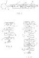
- FIG. 1 there is shown schematically an internal combustion engine 10 having an associated air intake system 12 and exhaust system 14.
- a rotatable throttle valve 16 is included within the air intake system 12 for regulating air flow to the engine 10.
- the first sensor is a standard throttle position sensor 18, such as a potentiometer, which is connected to throttle valve 16 and develops an electrical signal TP related to the degree or percent of throttle valve opening.
- the second is a conventional engine rotational sensor, which includes a toothed wheel 42 mounted on the engine crankshaft, and an electromagnetic sensor 44 that produces a SPEED signal having pulses corresponding to the movement of teeth on wheel 42 past electromagnetic sensor 44.
- the particular toothed wheel 42 shown in Figure 1, has six symmetrically spaced teeth producing equally spaced pulses in the engine SPEED signal, and a seventh asymmetrically spaced tooth than produces a synchronization pulse typically used for determining engine rotation from a known reference position.
- acoustic pressure waves are generated and propagate away from the engine through the ducts and tubes forming the air intake and exhaust systems. Eventually, these pressure waves propagate from openings in the intake and exhaust systems as observable engine induction noise 20 and exhaust noise 22. In addition, the engine generates noise in the form of mechanical vibrations 24, which are ultimately transferred to a mounting frame 40 used to support engine 10.
- Electronic noise controller 26 is a multi-channel device having three separate channels, with each channel operating independently to attenuate one of the different forms of engine noise.
- each channel of noise controller 26 would require a separate input sensor for deriving a signal representative of the noise to be cancelled by that channel.
- individual input sensors are not required, since the input signals for each channel can be generated from the engine rotational SPEED signal, as will be described subsequently.
- one channel of the noise controller 26 is utilized to attenuate the engine generated induction noise propagating inside the air intake system 12. Based upon an input signal associated with the engine induction noise, a cancelling OUTPUT signal is produced by noise controller 26.
- This OUTPUT signal drives a speaker 28, or any other type of suitable actuator capable of generating cancelling acoustic waves for superposition with the engine induction noise.
- An error microphone 30, or any other suitable acoustic sensor is employed to measure the level of the attenuated induction noise remaining in the air intake system 12, after the superposition of the cancelling acoustic waves, and to develop a corresponding analogue ERROR1 feedback signal.
- This ERROR1 signal is directed back to the induction noise channel of the electronic noise controller 26, and provides the basis for minimizing the observed induction noise 20 propagating out of engine 10.
- a noise cancelling OUTPUT2 signal is produced to drive the exhaust actuator or speaker 32, and an ERROR2 signal is developed by microphone 34 to act as feedback for the exhaust noise channel of noise controller 26.
- a third channel of the noise controller 26 produces noise cancelling signal OUTPUT3 to drive an electromagnetic shaker 36, which is disposed between engine 10 and mounting frame 40.
- Electromagnetic shaker 36 may be any type of actuator known to those skilled in the art, as for example, a commercially available Model 203B Shaker supplied by Ling Electronics, Inc., which is capable of producing the required out-of-phase cancelling vibrations.
- an error feedback signal ERROR3 representing the residual vibrations transferred to mounting frame 40 is developed by an error sensor 38, such as an accelerometer, which is attached to the mounting frame 40.
- the electronic noise controller 26 preferably includes a standard digital signal processor and the necessary interfacing circuitry such as analogue amplifiers and filters, analogue-to-digital and digital-to-analogue converters, frequency multipliers, counters, clocks, and other known input/output signal conditioning circuitry.
- the actual hardware implementation of noise controller 26 is not described herein, since such circuitry is well known in the art and is described in numerous publications and texts, see for example, "Hardware and Software Considerations for Active Noise Control", M. C. Allie, C. D. Bremigan, L. J. Eriksson, and R. A. Grainier, 1988, IEEE, CH 2561-9/88/0000-2598, pp. 2598-2601.
- Digital signal processors are commercially available, for example the Motorola 56000, and typically contain a central processing unit for carrying out instructions and arithmetic operations, random access memory for storing data, and read only memory for permanently storing program instruction.
- the digital signal processor When utilized for active noise control, the digital signal processor is typically programmed to function as a single adaptive digital filter. In the above described application, the digital signal processor is programmed to function as a multi-channel device, with each channel having a separate adaptive filter.
- the amplitudes of the various analogue signals directed to the noise controller 26 are sampled at a fixed sampling rate and sets of these sample values are retained for use in computing digital output signals using the adaptive filtering algorithms of the separate channels.
- the digital output signals are then converted to analogue form and appropriately amplified to provide the signals necessary for driving the system cancellation actuators.
- an indication of the angular rotation of the engine is derived from the engine SPEED signal produced by the engine rotational sensor described previously, however, any other known means for sensing engine rotation could also be employed.
- the block diagram shown in Figure 2 represents circuitry within noise controller 26 used to process the engine SPEED signal.
- the SPEED signal which contains pulses generated by the movement of toothed wheel 42 past electromagnetic sensor 44, is passed to the conditioning circuitry 46, where the asymmetrical synchronization pulse is eliminated and the remaining symmetrical pulses are shaped to be compatible with the digital format of the noise controller 26.
- These formatted digital pulses representing crankshaft angular rotation are then passed to a standard frequency multiplier/divider, which generates a fixed number of pulses during one complete rotation of the engine crankshaft.
- These pulses are then counted by a conventional modulo counter, to provide an output COUNT signal, which is indicative of the rotational position of the crankshaft in the engine cycle at any given time.
- the number of teeth on wheel 42, the frequency multiplier/divider, and the modulo counter are selected to provide an integer count ranging in value from 0, to a maximum value of MAX, each time the engine completes a cycle, which in a four-stroke engine is two full revolutions of the engine crankshaft.
- the value of COUNT thus represents a derived indication of the angular rotation of the engine in the operating cycle.
- the noise controller 26 is able to generate a separate input signal for each channel representing the multiple harmonic components selected for attenuation of noise associated with that particular channel.
- FIG. 3 there is shown a flow diagram representative of the program steps that would be executed by electronic noise controller 26 in one embodiment of the present invention, in generating a channel input signal representing multiple harmonic components selected for attenuation.
- the Input Signal Generating Routine is entered at point 52, after each system interrupt associated with the sampling rate of the digital signal processor contained within electronic noise controller 26.
- the program then proceeds to step 54, where the current COUNT of the previously described modulo counter is read and stored. As described later, it may also be desirable at this step to establish a value for RPM, the rotational speed of the engine.
- the current value representing RPM can then be determined by multiplying the resulting angular rotation of the engine by a fixed scaling constant to convert to revolutions per minute.
- q 2 ⁇ /(MAX+1)
- m the order of the largest harmonic related to engine rotational speed that is of interest.
- a form of noise produced by a given engine is measured to determine the order of the dominant harmonic components present within the noise.
- the amplitudes A, B, C, ..., and M of the harmonic components in the above equation, which are selected to be attenuated in the engine noise are set equal to unity, and the amplitudes of those not selected for attenuation are set to zero.
- table values for INPUT are computed for each possible integer value of COUNT, using the equation presented above. Prior to storage in the table, all of the calculated INPUT values are normalized to range between -1 and 1, by dividing each by the maximum magnitude found for the table INPUT values.
- relative values for the amplitudes A, B, C, ..., and M of the selected noise harmonics could be found by measuring the noise to be attenuated and determining an average amplitude value for each harmonic component, while running the engine on a dynamometer at different speeds over the operating range of the engine.
- the INPUT table can contain different schedules for different ranges of engine operating speed.
- the values for each separate schedule can then be computed, as described above, to correspond to the dominant noise harmonics produced by the engine, when it operates within the associated range of engine speed.
- the current engine speed as represented by the value of RPM derived in step 54, is used to select the appropriate INPUT table schedule, from which a sample for the input signal is looked up, based upon the current value of COUNT.
- step 64 the value for INPUT is stored in memory as INPUT(n), which represents the most recently generated sample value for the INPUT signal.
- INPUT(n) the value for INPUT is stored in memory as INPUT(n), which represents the most recently generated sample value for the INPUT signal.
- the previous value is shifted and stored in memory as INPUT(n-1), and so forth down to the last retained sample in the sequence INPUT(n-N+1), where N represents the number of sequential sample values of the INPUT signal retained in memory for later use by the noise controller 26.
- the routine is exited with the sequence of generated INPUT samples acting as a channel input signal representing the multiple harmonic noise components selected for attenuation by that channel of the noise controller 26. Because the generation of the input signal is based upon the current value of COUNT from the modulo counter, the input signal is automatically synchronized to the rotation of the engine, which assures correspondence between the frequencies of components contained within the generated signal and the noise harmonics produced by the engine.
- the amplitude of the input signal generated to represent the multiple engine noise harmonics is modulated as a function of engine loading (derived by measuring the position of the throttle valve 16, or intake manifold vacuum or engine mass air flow), in the manner described in copending application no. 91201872.8.
- FIG 4 there is shown a flow diagram representing the program steps that are executed by noise controller 26, when generating a channel input signal that has its amplitude modulated as a function of engine loading. Note that corresponding steps in the flow diagrams of Figures 3 and 4 have been designated with the same numerals.
- the Modulated Input Signal Generating Routine is entered at step 68 and proceeds through the same steps 54 and 56, previously described in conjunction with Figure 3, to look up a sample value for INPUT.
- noise controller 26 reads the current position of the throttle valve by sampling the value of the analogue throttle position signal TP. This value for TP is stored, and the program then proceeds to step 72.
- a value for MOD is looked up in a stored schedule, as a function of the current position of the throttle found in step 70.
- the schedule values for the modulation factor MOD will be dependent both upon the form of the noise and the type of engine producing it.
- Values for the MOD table can be determined by measuring the particular form of noise to be attenuated, while operating an engine on a dynamometer.
- the value representing MOD for each position of the throttle are found by determining the average level of noise produced, while varying engine speed with the throttle position fixed. All such measured average values are normalized prior to storage in the MOD schedule, by dividing each average value by the maximum average value found during testing. In this way, the stored values in the MOD schedule are scaled to range between 0 and 1.
- a new amplitude modulated value for INPUT is computed by multiplying INPUT ⁇ 1, the value of INPUT found at step 56, by the modulation factor MOD found at step 72.
- step 64 the current value for INPUT is stored in memory as INPUT(n), which represents the most recently generated sample value for the amplitude modulated INPUT signal.
- INPUT(n) the current value for INPUT is stored in memory as INPUT(n), which represents the most recently generated sample value for the amplitude modulated INPUT signal.
- the previous value is shifted and stored in memory as INPUT(n-1), and so forth down to the last retained sample in the sequence INPUT(n-N+1).
- the routine is exited as step 66, with the sequence of generated INPUT samples representing a channel input signal, which has its amplitude modulated as a function of engine loading.
- a sequence of sample values representing the input signal for a particular channel of the noise controller 26 can thus be derived using either of the routines of Figures 3 and 4.
- a corresponding sequence of sample values ERROR(n), ERROR(n-1), ... , ERROR(n-N+1) is obtained for each channel by sampling each channel's analogue error signal at the system sampling rate and then stored in the memory of the noise controller 26.
- noise controller 26 uses these sample values for the channel input and error signals, noise controller 26 computes a sample value OUTPUT(n) for the channel output signal using an adaptive filtering algorithm.
- the noise controller 26 converts the consecutively computed digital samples OUTPUT(n) into an analogue waveform, which is then amplified to produce the OUTPUT cancelling signal used to drive the channel's cancellation actuator.
- one of the advantages associated with the above embodiments is the elimination of the need for separate channel input sensors for measuring each form of engine noise to be attenuated by the separate channels of the noise controller 26.
- the conventional feedback path between the traditional input sensor and the cancellation actuator is eliminated, and non-recursive type adaptive filtering algorithms can then be used to compute the channel OUTPUT(n) samples.
- non-recursive digital algorithms are computationally less complex, and require less memory and processing time to execute.
- FIG. 5 there is shown a schematic diagram for a Filtered X Least Mean Squares (LMS) adaptive filter, which is the type of non-recursive filtering algorithm utilized for the preferred embodiments of the present invention.
- LMS Filtered X Least Mean Squares
- Consecutive sample values for a channel OUTPUT(n) signal are produced at the system sampling rate, by adaptively filtering the most recent INPUT(n) sample, and the other retained samples in the INPUT sequence, using the non-recursive digital A filter 76.
- New sample values for OUTPUT(n) are computed on the basis of the following algorithm: where the set A i (n) represents the most recently computed adaptive filter coefficients for the A filter, and N represents the size of the filter, as well as the number of samples of generated input signal retained in memory.
- the adaptive filter coefficients A i (n) are updated as indicated by the UPDATE A block 77 in the diagram, in order to minimize the ERROR(n) sample values, which represent the residual engine noise remaining after the superposition of the cancelling noise waveform.
- the UPDATE A block 77 has two inputs, the first being ERROR(n), and the second being a filtered sequence of sample values designated as INPUT'(n) derived by passing the corresponding sequence of input signal samples INPUT(n) through the auxiliary E filter 78.
- a i (n+1) g * A i (n) - u * ERROR(n) * INPUT'(n-i), (3)
- g represents the filter leakage coefficient having a value in the range of 0 ⁇ g ⁇ 1
- u represents the filter convergence factor having a value in the range of 0 ⁇ u ⁇ 1.
- the sequence of sample values for the INPUT'(n) signal in equation (3) are obtained by filtering the sequence of INPUT(n) values with the auxiliary E filter 78 on the basis of the following equation: where E i (n) represents the fixed weighting coefficients for the auxiliary E filter.
- the auxiliary E filter 78 is used to compensate for the distortion produced by components in the channel error path of the active noise control system.
- This error path typically includes the channel cancellation actuator and the associated output circuitry within noise controller 26; the error sensor and the associated error input circuitry within noise controller 26; and the characteristics of the physical path between the channel cancellation actuator and error sensor, over which the engine noise propagates.
- FIG. 6 there is shown a schematic diagram representing the process used in calibrating a channel auxiliary E filter 78 to obtain its fixed weighting coefficients.
- the auxiliary E filter is calibrated to have a transfer function equivalent to the combined components in the channel error path.
- the components in the error path such as the cancellation actuator 82, noise propagation path 84, and error sensor 86, must remain in the same physical locations, as when they are used in attenuating the engine noise associated with that channel.
- the calibration process uses a conventional RANDOM NOISE SOURCE 80 to generate a sequence of random signal values designated as IN(n).
- the random signal samples are directed as input to the auxiliary E filter 78, and are also passed through the components of the error path to produce a corresponding sequence of samples designated as D(n).
- the IN(n) samples are subjected to the same components as are the OUTPUT(n) samples and the resulting ERROR(n) samples of Figure 5.
- the Filtered X Least Mean Squares (LMS) adaptive filter has been described as the preferred type of non-recursive adaptive filter used in the preferred embodiments, it should be understood that other types of adaptive filters, recursive as well as non-recursive, may also be used.
- the computational efficiency associated with the Filtered X Least Mean Squares (LMS) adaptive filter permits a single digital signal processor to be programmed to function as a multi-channel device so that more than one form of engine noise can be attenuated with a single noise controller.
Applications Claiming Priority (2)
| Application Number | Priority Date | Filing Date | Title |
|---|---|---|---|
| US594495 | 1990-10-04 | ||
| US07/594,495 US5146505A (en) | 1990-10-04 | 1990-10-04 | Method for actively attenuating engine generated noise |
Publications (3)
| Publication Number | Publication Date |
|---|---|
| EP0479367A2 true EP0479367A2 (de) | 1992-04-08 |
| EP0479367A3 EP0479367A3 (en) | 1992-09-02 |
| EP0479367B1 EP0479367B1 (de) | 1995-08-09 |
Family
ID=24379114
Family Applications (1)
| Application Number | Title | Priority Date | Filing Date |
|---|---|---|---|
| EP91202477A Expired - Lifetime EP0479367B1 (de) | 1990-10-04 | 1991-09-20 | Verfahren und Gerät zur Dampfung von maschinenerregten Rauschen |
Country Status (3)
| Country | Link |
|---|---|
| US (1) | US5146505A (de) |
| EP (1) | EP0479367B1 (de) |
| DE (1) | DE69111959T2 (de) |
Cited By (24)
| Publication number | Priority date | Publication date | Assignee | Title |
|---|---|---|---|---|
| EP0560364A1 (de) * | 1992-03-12 | 1993-09-15 | Honda Giken Kogyo Kabushiki Kaisha | Schwingungs- und Geräuschregelungssystem für Kraftfahrzeuge |
| GB2265277A (en) * | 1992-03-17 | 1993-09-22 | Fuji Heavy Ind Ltd | Noise reduction system for automobile compartment |
| EP0568127A2 (de) * | 1992-04-29 | 1993-11-03 | General Motors Corporation | Geräuschminderungssystem |
| EP0568128A2 (de) * | 1992-04-29 | 1993-11-03 | General Motors Corporation | Geräuschminderungssystem |
| EP0568129A2 (de) * | 1992-04-29 | 1993-11-03 | General Motors Corporation | Geräuschminderungssystem |
| EP0585875A2 (de) * | 1992-08-31 | 1994-03-09 | Mazda Motor Corporation | Kraftwagenvibrationsdampfungsanordnung |
| DE4333384A1 (de) * | 1992-09-30 | 1994-03-31 | Mazda Motor | Vibrationsdämpfungssystem für ein Fahrzeug |
| EP0592693A1 (de) * | 1992-05-01 | 1994-04-20 | Fujitsu Ten, Ltd. | Lärmkontrollegerät |
| EP0609846A2 (de) * | 1993-02-02 | 1994-08-10 | Honda Giken Kogyo Kabushiki Kaisha | Schwingungs/Lärmkontrollevorrichtung |
| EP0625773A2 (de) * | 1993-05-21 | 1994-11-23 | Nippondenso Co., Ltd. | Motorlärmkontrollegerät |
| EP0659288A4 (de) * | 1992-07-14 | 1995-03-01 | Noise Cancellation Tech | Preisgünstiger regler. |
| WO1995014988A1 (en) * | 1993-11-29 | 1995-06-01 | Caterpillar Inc. | Indirectly sensed signal processing in active periodic acoustic noise cancellation |
| EP0720144A1 (de) * | 1994-12-28 | 1996-07-03 | FIAT AUTO S.p.A. | Gerauschverringerungsverfahren hervorgerufen durch Kraftfahrzeug Schwingungen |
| GB2305328A (en) * | 1995-08-26 | 1997-04-02 | Fichtel & Sachs Ag | Controlling vibrations in a passenger compartment of a motor vehicle and detecting dfects in a motor vehicle |
| US5692052A (en) * | 1991-06-17 | 1997-11-25 | Nippondenso Co., Ltd. | Engine noise control apparatus |
| EP0818771A2 (de) * | 1996-07-09 | 1998-01-14 | Nec Corporation | Gebläselärmdämpfer |
| US5822439A (en) * | 1992-05-01 | 1998-10-13 | Fujitsu Ten Limited | Noise control device |
| WO2003009275A1 (en) * | 2001-07-19 | 2003-01-30 | Siemens Vdo Automotive Inc. | Active noise cancellation system utilizing a signal delay to accommodate noise phase change |
| FR2881256A1 (fr) * | 2005-01-21 | 2006-07-28 | Peugeot Citroen Automobiles Sa | Dispositif et procede de determination d'un etat de fonctionnement et systeme et procede de pilotage correspondant |
| DE102012113035A1 (de) * | 2012-12-21 | 2014-06-26 | Dr. Ing. H.C. F. Porsche Aktiengesellschaft | Vorrichtung zur Geräuschoptimierung |
| DE102012113038A1 (de) * | 2012-12-21 | 2014-06-26 | Dr. Ing. H.C. F. Porsche Aktiengesellschaft | Verfahren und Vorrichtung zur Geräuschoptimierung |
| DE102012113036A1 (de) * | 2012-12-21 | 2014-06-26 | Dr. Ing. H.C. F. Porsche Aktiengesellschaft | Vorrichtung zur Geräuschoptimierung |
| WO2017204916A1 (en) * | 2016-05-25 | 2017-11-30 | Wichita State University | Hybrid method to synthesize voltage waveforms with non-harmonic profiles |
| EP3761306A3 (de) * | 2019-07-01 | 2021-04-21 | Harman International Industries, Incorporated | Antriebsmodusoptimierte motorordnungsunterdrückung |
Families Citing this family (49)
| Publication number | Priority date | Publication date | Assignee | Title |
|---|---|---|---|---|
| US5457749A (en) * | 1990-04-09 | 1995-10-10 | Noise Cancellation Technologies, Inc. | Electronic muffler |
| US5323466A (en) * | 1990-04-25 | 1994-06-21 | Ford Motor Company | Tandem transducer magnet structure |
| US5319165A (en) * | 1990-04-25 | 1994-06-07 | Ford Motor Company | Dual bandpass secondary source |
| US5404409A (en) * | 1991-07-31 | 1995-04-04 | Fujitsu Ten Limited | Adaptive filtering means for an automatic sound controlling apparatus |
| US5548653A (en) * | 1992-02-14 | 1996-08-20 | General Electric Company | Active control of noise and vibrations in magnetic resonance imaging systems using vibrational inputs |
| US5313407A (en) * | 1992-06-03 | 1994-05-17 | Ford Motor Company | Integrated active vibration cancellation and machine diagnostic system |
| US5426704A (en) * | 1992-07-22 | 1995-06-20 | Pioneer Electronic Corporation | Noise reducing apparatus |
| WO1994009483A1 (en) * | 1992-10-08 | 1994-04-28 | Noise Cancellation Technologies, Inc. | Multiple source self noise cancellation |
| US5692054A (en) * | 1992-10-08 | 1997-11-25 | Noise Cancellation Technologies, Inc. | Multiple source self noise cancellation |
| US5394330A (en) * | 1992-11-12 | 1995-02-28 | Texas Instruments Incorporated | System and method for monitoring an operating state of an engine |
| JPH06242787A (ja) * | 1993-02-17 | 1994-09-02 | Fujitsu Ltd | 回り込み音制御式能動騒音消去装置 |
| US5332061A (en) * | 1993-03-12 | 1994-07-26 | General Motors Corporation | Active vibration control system for attenuating engine generated vibrations in a vehicle |
| US5414775A (en) * | 1993-05-26 | 1995-05-09 | Noise Cancellation Technologies, Inc. | Noise attenuation system for vibratory feeder bowl |
| WO1995008155A1 (en) * | 1993-09-17 | 1995-03-23 | Noise Cancellation Technologies, Inc. | Causal modeling of predictable impulse noise |
| US5440642A (en) * | 1993-09-20 | 1995-08-08 | Denenberg; Jeffrey N. | Analog noise cancellation system using digital optimizing of variable parameters |
| US5488666A (en) * | 1993-10-01 | 1996-01-30 | Greenhalgh Technologies | System for suppressing sound from a flame |
| US5473698A (en) * | 1993-11-23 | 1995-12-05 | Garnjost; Kenneth D. | Method of controlling the application of counter-vibration to a structure |
| US5475761A (en) * | 1994-01-31 | 1995-12-12 | Noise Cancellation Technologies, Inc. | Adaptive feedforward and feedback control system |
| US5478199A (en) * | 1994-11-28 | 1995-12-26 | General Electric Company | Active low noise fan assembly |
| JPH08158966A (ja) * | 1994-11-30 | 1996-06-18 | Nippondenso Co Ltd | 内燃機関の騒音制御装置 |
| US5526292A (en) * | 1994-11-30 | 1996-06-11 | Lord Corporation | Broadband noise and vibration reduction |
| US5754662A (en) * | 1994-11-30 | 1998-05-19 | Lord Corporation | Frequency-focused actuators for active vibrational energy control systems |
| US6201872B1 (en) | 1995-03-12 | 2001-03-13 | Hersh Acoustical Engineering, Inc. | Active control source cancellation and active control Helmholtz resonator absorption of axial fan rotor-stator interaction noise |
| US5715320A (en) * | 1995-08-21 | 1998-02-03 | Digisonix, Inc. | Active adaptive selective control system |
| US5710822A (en) * | 1995-11-07 | 1998-01-20 | Digisonix, Inc. | Frequency selective active adaptive control system |
| US6002778A (en) * | 1996-08-07 | 1999-12-14 | Lord Corporation | Active structural control system and method including active vibration absorbers (AVAS) |
| DE19749587C1 (de) * | 1997-11-10 | 1999-06-24 | Daimler Benz Ag | Verfahren und Vorrichtung zur Beeinflussung eines von einem Insassen eines Fahrzeuges, insbesondere eines PKW's, subjektiv wahrgenommenen Eindrucks beim Betreiben des Kraftfahrzeugs |
| DE10018666A1 (de) | 2000-04-14 | 2001-10-18 | Harman Audio Electronic Sys | Vorrichtung und Verfahren zum geräuschabhängigen Anpassen eines akustischen Nutzsignals |
| US20040125962A1 (en) * | 2000-04-14 | 2004-07-01 | Markus Christoph | Method and apparatus for dynamic sound optimization |
| US6644590B2 (en) | 2000-09-15 | 2003-11-11 | General Dynamics Advanced Information Systems, Inc. | Active system and method for vibration and noise reduction |
| US6402089B1 (en) | 2001-03-02 | 2002-06-11 | General Dynamics Advanced Technology Services, Inc. | System for control of active system for vibration and noise reduction |
| US6622647B2 (en) | 2001-06-26 | 2003-09-23 | Depoy Martin L. | Active noise cancellation for a torpedo seeker head |
| US20040013273A1 (en) * | 2002-07-22 | 2004-01-22 | Siemens Vdo Automotive, Inc. | Calibration for an active noise control system |
| JP2005134749A (ja) * | 2003-10-31 | 2005-05-26 | Roland Corp | 自動車音処理装置 |
| EP1580882B1 (de) * | 2004-03-19 | 2007-01-10 | Harman Becker Automotive Systems GmbH | System und Verfahren zur Verbesserung eines Audiosignals |
| EP1833163B1 (de) * | 2004-07-20 | 2019-12-18 | Harman Becker Automotive Systems GmbH | Audioverbesserungssystem und -verfahren |
| US8170221B2 (en) * | 2005-03-21 | 2012-05-01 | Harman Becker Automotive Systems Gmbh | Audio enhancement system and method |
| DE602005015426D1 (de) | 2005-05-04 | 2009-08-27 | Harman Becker Automotive Sys | System und Verfahren zur Intensivierung von Audiosignalen |
| US20070125592A1 (en) * | 2005-12-07 | 2007-06-07 | Frank Michell | Excitation of air directing valves and air handling surfaces in the cancellation of air handling system noise |
| DE102012200712B4 (de) * | 2012-01-19 | 2015-07-09 | Eberspächer Exhaust Technology GmbH & Co. KG | Abgasvorrichtung für eine Brennkraftmaschine |
| US9286882B1 (en) | 2012-03-07 | 2016-03-15 | Great Lakes Sound & Vibration, Inc. | Systems and methods for active exhaust noise cancellation |
| CN103531195A (zh) * | 2012-07-02 | 2014-01-22 | 华为技术有限公司 | 降噪方法及设备、系统 |
| US9523322B2 (en) * | 2012-12-14 | 2016-12-20 | Continental Automotive Systems, Inc. | Method to reduce engine combustion and harmonic noise for misfire detection |
| US9167067B2 (en) | 2013-02-14 | 2015-10-20 | Bose Corporation | Motor vehicle noise management |
| US9269344B2 (en) * | 2013-09-03 | 2016-02-23 | Bose Corporation | Engine harmonic cancellation system afterglow mitigation |
| US9881602B2 (en) * | 2014-07-11 | 2018-01-30 | Tenneco Gmbh | Sound system for a motor vehicle |
| US9376116B1 (en) | 2015-03-09 | 2016-06-28 | Caterpillar Inc. | Control system for reducing powertrain induced vibrations |
| DE102017111479A1 (de) * | 2017-05-24 | 2018-11-29 | Hengst Se | Verfahren zum Betreiben eines Zentrifugalabscheiders |
| DE102018219644A1 (de) * | 2018-11-16 | 2020-05-20 | Zf Friedrichshafen Ag | Aktive Reduktion von Schallemissionen an einem Kraftfahrzeug |
Citations (3)
| Publication number | Priority date | Publication date | Assignee | Title |
|---|---|---|---|---|
| EP0098594A2 (de) * | 1982-07-07 | 1984-01-18 | Nissan Motor Co., Ltd. | Verfahren und Anordnung zur Kontrolle des akustischen Feldes in einer Fahrerkabine |
| US4614117A (en) * | 1983-07-11 | 1986-09-30 | Mitsubishi Denki Kabushiki Kaisha | Vibration monitoring apparatus |
| US4878188A (en) * | 1988-08-30 | 1989-10-31 | Noise Cancellation Tech | Selective active cancellation system for repetitive phenomena |
Family Cites Families (5)
| Publication number | Priority date | Publication date | Assignee | Title |
|---|---|---|---|---|
| GB1577322A (en) * | 1976-05-13 | 1980-10-22 | Bearcroft R | Active attenuation of recurring vibrations |
| US4417098A (en) * | 1979-08-16 | 1983-11-22 | Sound Attenuators Limited | Method of reducing the adaption time in the cancellation of repetitive vibration |
| JPH0634553B2 (ja) * | 1986-09-18 | 1994-05-02 | トヨタ自動車株式会社 | 車両のこもり音抑制装置 |
| US5022082A (en) * | 1990-01-12 | 1991-06-04 | Nelson Industries, Inc. | Active acoustic attenuation system with reduced convergence time |
| US5010576A (en) * | 1990-01-22 | 1991-04-23 | Westinghouse Electric Corp. | Active acoustic attenuation system for reducing tonal noise in rotating equipment |
-
1990
- 1990-10-04 US US07/594,495 patent/US5146505A/en not_active Expired - Fee Related
-
1991
- 1991-09-20 DE DE69111959T patent/DE69111959T2/de not_active Expired - Fee Related
- 1991-09-20 EP EP91202477A patent/EP0479367B1/de not_active Expired - Lifetime
Patent Citations (3)
| Publication number | Priority date | Publication date | Assignee | Title |
|---|---|---|---|---|
| EP0098594A2 (de) * | 1982-07-07 | 1984-01-18 | Nissan Motor Co., Ltd. | Verfahren und Anordnung zur Kontrolle des akustischen Feldes in einer Fahrerkabine |
| US4614117A (en) * | 1983-07-11 | 1986-09-30 | Mitsubishi Denki Kabushiki Kaisha | Vibration monitoring apparatus |
| US4878188A (en) * | 1988-08-30 | 1989-10-31 | Noise Cancellation Tech | Selective active cancellation system for repetitive phenomena |
Non-Patent Citations (2)
| Title |
|---|
| FREQUENCY NOISE GETS WAVED BACK' * |
| MACHINE DESIGN. vol. 59, no. 29, 10 December 1987, CLEVELAND US page 70; 'LOW-FREQUENCY NOISE GETS WAVED BACK' * |
Cited By (44)
| Publication number | Priority date | Publication date | Assignee | Title |
|---|---|---|---|---|
| US5692052A (en) * | 1991-06-17 | 1997-11-25 | Nippondenso Co., Ltd. | Engine noise control apparatus |
| US5386372A (en) * | 1992-03-12 | 1995-01-31 | Honda Giken Kogyo Kabushiki Kaisha | Vibration/noise control system for vehicles |
| EP0560364A1 (de) * | 1992-03-12 | 1993-09-15 | Honda Giken Kogyo Kabushiki Kaisha | Schwingungs- und Geräuschregelungssystem für Kraftfahrzeuge |
| GB2265277B (en) * | 1992-03-17 | 1996-07-24 | Fuji Heavy Ind Ltd | Noise reduction system for automobile compartment |
| GB2265277A (en) * | 1992-03-17 | 1993-09-22 | Fuji Heavy Ind Ltd | Noise reduction system for automobile compartment |
| US5485523A (en) * | 1992-03-17 | 1996-01-16 | Fuji Jukogyo Kabushiki Kaisha | Active noise reduction system for automobile compartment |
| EP0568127A3 (en) * | 1992-04-29 | 1994-07-13 | Gen Motors Corp | Noise attenuation system |
| EP0568129A3 (de) * | 1992-04-29 | 1994-08-31 | Gen Motors Corp | |
| EP0568128A3 (de) * | 1992-04-29 | 1994-08-31 | Gen Motors Corp | |
| EP0568129A2 (de) * | 1992-04-29 | 1993-11-03 | General Motors Corporation | Geräuschminderungssystem |
| EP0568128A2 (de) * | 1992-04-29 | 1993-11-03 | General Motors Corporation | Geräuschminderungssystem |
| EP0568127A2 (de) * | 1992-04-29 | 1993-11-03 | General Motors Corporation | Geräuschminderungssystem |
| EP0592693A1 (de) * | 1992-05-01 | 1994-04-20 | Fujitsu Ten, Ltd. | Lärmkontrollegerät |
| EP0817165A1 (de) * | 1992-05-01 | 1998-01-07 | Fujitsu Ten Limited | Lärmkontrollegerät |
| EP0817166A1 (de) * | 1992-05-01 | 1998-01-07 | Fujitsu Ten Limited | Lärmkontrollegerät |
| EP0592693A4 (en) * | 1992-05-01 | 1994-09-28 | Fujitsu Ten Ltd | Noise control device |
| US5822439A (en) * | 1992-05-01 | 1998-10-13 | Fujitsu Ten Limited | Noise control device |
| EP0659288A4 (de) * | 1992-07-14 | 1995-03-01 | Noise Cancellation Tech | Preisgünstiger regler. |
| EP0659288A1 (de) * | 1992-07-14 | 1995-06-28 | Noise Cancellation Technologies, Inc. | Preisgünstiger regler |
| EP0585875A3 (de) * | 1992-08-31 | 1995-08-02 | Mazda Motor | Kraftwagenvibrationsdampfungsanordnung. |
| US5617315A (en) * | 1992-08-31 | 1997-04-01 | Mazda Motor Corporation | Active vibration damping system for a vehicle |
| EP0585875A2 (de) * | 1992-08-31 | 1994-03-09 | Mazda Motor Corporation | Kraftwagenvibrationsdampfungsanordnung |
| DE4333384A1 (de) * | 1992-09-30 | 1994-03-31 | Mazda Motor | Vibrationsdämpfungssystem für ein Fahrzeug |
| EP0609846A3 (en) * | 1993-02-02 | 1995-10-11 | Honda Motor Co Ltd | Vibration/noise control system. |
| EP0609846A2 (de) * | 1993-02-02 | 1994-08-10 | Honda Giken Kogyo Kabushiki Kaisha | Schwingungs/Lärmkontrollevorrichtung |
| EP0625773A3 (de) * | 1993-05-21 | 1995-10-18 | Nippon Denso Co | Motorlärmkontrollegerät. |
| EP0625773A2 (de) * | 1993-05-21 | 1994-11-23 | Nippondenso Co., Ltd. | Motorlärmkontrollegerät |
| US5502770A (en) * | 1993-11-29 | 1996-03-26 | Caterpillar Inc. | Indirectly sensed signal processing in active periodic acoustic noise cancellation |
| WO1995014988A1 (en) * | 1993-11-29 | 1995-06-01 | Caterpillar Inc. | Indirectly sensed signal processing in active periodic acoustic noise cancellation |
| EP0720144A1 (de) * | 1994-12-28 | 1996-07-03 | FIAT AUTO S.p.A. | Gerauschverringerungsverfahren hervorgerufen durch Kraftfahrzeug Schwingungen |
| ES2120370A1 (es) * | 1995-08-26 | 1998-10-16 | Fichtel & Sachs Ag | Dispositivo y procedimiento para influir sobre vibraciones en un habitaculo de un automovil y dispositivo y procedimiento para la deteccion de defectos en un automovil. |
| GB2305328A (en) * | 1995-08-26 | 1997-04-02 | Fichtel & Sachs Ag | Controlling vibrations in a passenger compartment of a motor vehicle and detecting dfects in a motor vehicle |
| US5748748A (en) * | 1995-08-26 | 1998-05-05 | Fichtel & Sachs Ag | Apparatus and method for influencing oscillations in the passenger compartment of a motor vehicle and apparatus and method for detecting defects in a motor vehicle |
| US6188770B1 (en) | 1996-07-09 | 2001-02-13 | Nec Corporation | Fan noise canceller |
| EP0818771A3 (de) * | 1996-07-09 | 1999-01-13 | Nec Corporation | Gebläselärmdämpfer |
| US5995632A (en) * | 1996-07-09 | 1999-11-30 | Nec Corporation | Fan noise canceller |
| EP0818771A2 (de) * | 1996-07-09 | 1998-01-14 | Nec Corporation | Gebläselärmdämpfer |
| WO2003009275A1 (en) * | 2001-07-19 | 2003-01-30 | Siemens Vdo Automotive Inc. | Active noise cancellation system utilizing a signal delay to accommodate noise phase change |
| FR2881256A1 (fr) * | 2005-01-21 | 2006-07-28 | Peugeot Citroen Automobiles Sa | Dispositif et procede de determination d'un etat de fonctionnement et systeme et procede de pilotage correspondant |
| DE102012113035A1 (de) * | 2012-12-21 | 2014-06-26 | Dr. Ing. H.C. F. Porsche Aktiengesellschaft | Vorrichtung zur Geräuschoptimierung |
| DE102012113038A1 (de) * | 2012-12-21 | 2014-06-26 | Dr. Ing. H.C. F. Porsche Aktiengesellschaft | Verfahren und Vorrichtung zur Geräuschoptimierung |
| DE102012113036A1 (de) * | 2012-12-21 | 2014-06-26 | Dr. Ing. H.C. F. Porsche Aktiengesellschaft | Vorrichtung zur Geräuschoptimierung |
| WO2017204916A1 (en) * | 2016-05-25 | 2017-11-30 | Wichita State University | Hybrid method to synthesize voltage waveforms with non-harmonic profiles |
| EP3761306A3 (de) * | 2019-07-01 | 2021-04-21 | Harman International Industries, Incorporated | Antriebsmodusoptimierte motorordnungsunterdrückung |
Also Published As
| Publication number | Publication date |
|---|---|
| DE69111959T2 (de) | 1995-11-23 |
| DE69111959D1 (de) | 1995-09-14 |
| EP0479367A3 (en) | 1992-09-02 |
| EP0479367B1 (de) | 1995-08-09 |
| US5146505A (en) | 1992-09-08 |
Similar Documents
| Publication | Publication Date | Title |
|---|---|---|
| EP0479367B1 (de) | Verfahren und Gerät zur Dampfung von maschinenerregten Rauschen | |
| US5359662A (en) | Active noise control system | |
| US5321759A (en) | Active noise control system for attenuating engine generated noise | |
| US5222148A (en) | Active noise control system for attenuating engine generated noise | |
| US5386472A (en) | Active noise control system | |
| EP0285632B1 (de) | Aktive vibrationskontrolle | |
| US5170433A (en) | Active vibration control | |
| US4878188A (en) | Selective active cancellation system for repetitive phenomena | |
| EP0361968B1 (de) | Lärmunterdrücker | |
| JP2997490B2 (ja) | 他の干渉する周期的雑音が存在する際に周期的信号を検知するための信号処理手段 | |
| US5912821A (en) | Vibration/noise control system including adaptive digital filters for simulating dynamic characteristics of a vibration/noise source having a rotating member | |
| US20040247137A1 (en) | Apparatus for and method of actively controlling vibratory noise, and vehicle with active vibratory noise control apparatus | |
| US4947435A (en) | Method of transfer function generation and active noise cancellation in a vibrating system | |
| US20060056642A1 (en) | Active vibratory noise control apparatus | |
| EP0609846A2 (de) | Schwingungs/Lärmkontrollevorrichtung | |
| JPH08510566A (ja) | 雑音整形のための能動制御装置 | |
| US5577127A (en) | System for rapid convergence of an adaptive filter in the generation of a time variant signal for cancellation of a primary signal | |
| EP0492680B1 (de) | Verfahren und Gerät zur Lärmdämpfung | |
| EP0470656A1 (de) | Verfahren und Einrichtung zur Dämpfung von Motorgeräusch | |
| JPH07133842A (ja) | 能動型振動制御装置 | |
| JPH0844377A (ja) | 周期性信号の適応制御方法 | |
| JP2770286B2 (ja) | 振動騒音制御装置 | |
| JP2798843B2 (ja) | 能動型騒音制御装置 | |
| JPH06266373A (ja) | 騒音キャンセル方式 | |
| JP3367133B2 (ja) | 車両用能動型騒音制御装置及び車両用能動型振動制御装置 |
Legal Events
| Date | Code | Title | Description |
|---|---|---|---|
| PUAI | Public reference made under article 153(3) epc to a published international application that has entered the european phase |
Free format text: ORIGINAL CODE: 0009012 |
|
| AK | Designated contracting states |
Kind code of ref document: A2 Designated state(s): DE FR GB |
|
| PUAL | Search report despatched |
Free format text: ORIGINAL CODE: 0009013 |
|
| AK | Designated contracting states |
Kind code of ref document: A3 Designated state(s): DE FR GB |
|
| 17P | Request for examination filed |
Effective date: 19921005 |
|
| 17Q | First examination report despatched |
Effective date: 19940309 |
|
| GRAA | (expected) grant |
Free format text: ORIGINAL CODE: 0009210 |
|
| AK | Designated contracting states |
Kind code of ref document: B1 Designated state(s): DE FR GB |
|
| REF | Corresponds to: |
Ref document number: 69111959 Country of ref document: DE Date of ref document: 19950914 |
|
| ET | Fr: translation filed | ||
| PLBE | No opposition filed within time limit |
Free format text: ORIGINAL CODE: 0009261 |
|
| STAA | Information on the status of an ep patent application or granted ep patent |
Free format text: STATUS: NO OPPOSITION FILED WITHIN TIME LIMIT |
|
| 26N | No opposition filed | ||
| PGFP | Annual fee paid to national office [announced via postgrant information from national office to epo] |
Ref country code: GB Payment date: 20000904 Year of fee payment: 10 |
|
| PGFP | Annual fee paid to national office [announced via postgrant information from national office to epo] |
Ref country code: FR Payment date: 20000915 Year of fee payment: 10 |
|
| PG25 | Lapsed in a contracting state [announced via postgrant information from national office to epo] |
Ref country code: GB Free format text: LAPSE BECAUSE OF NON-PAYMENT OF DUE FEES Effective date: 20010920 |
|
| PGFP | Annual fee paid to national office [announced via postgrant information from national office to epo] |
Ref country code: DE Payment date: 20011026 Year of fee payment: 11 |
|
| REG | Reference to a national code |
Ref country code: GB Ref legal event code: IF02 |
|
| GBPC | Gb: european patent ceased through non-payment of renewal fee |
Effective date: 20010920 |
|
| PG25 | Lapsed in a contracting state [announced via postgrant information from national office to epo] |
Ref country code: FR Free format text: LAPSE BECAUSE OF NON-PAYMENT OF DUE FEES Effective date: 20020531 |
|
| REG | Reference to a national code |
Ref country code: FR Ref legal event code: ST |
|
| PG25 | Lapsed in a contracting state [announced via postgrant information from national office to epo] |
Ref country code: DE Free format text: LAPSE BECAUSE OF NON-PAYMENT OF DUE FEES Effective date: 20030401 |