EP0479129A2 - Dispositif et procédé pour la localisation et la fixation d'inserts sur un coffrage pour la fabrication d'éléments de construction préfabriqués en béton - Google Patents
Dispositif et procédé pour la localisation et la fixation d'inserts sur un coffrage pour la fabrication d'éléments de construction préfabriqués en béton Download PDFInfo
- Publication number
- EP0479129A2 EP0479129A2 EP91116435A EP91116435A EP0479129A2 EP 0479129 A2 EP0479129 A2 EP 0479129A2 EP 91116435 A EP91116435 A EP 91116435A EP 91116435 A EP91116435 A EP 91116435A EP 0479129 A2 EP0479129 A2 EP 0479129A2
- Authority
- EP
- European Patent Office
- Prior art keywords
- adhesive
- built
- pallet
- gripper
- coordinate
- Prior art date
- Legal status (The legal status is an assumption and is not a legal conclusion. Google has not performed a legal analysis and makes no representation as to the accuracy of the status listed.)
- Withdrawn
Links
Images
Classifications
-
- B—PERFORMING OPERATIONS; TRANSPORTING
- B28—WORKING CEMENT, CLAY, OR STONE
- B28B—SHAPING CLAY OR OTHER CERAMIC COMPOSITIONS; SHAPING SLAG; SHAPING MIXTURES CONTAINING CEMENTITIOUS MATERIAL, e.g. PLASTER
- B28B23/00—Arrangements specially adapted for the production of shaped articles with elements wholly or partly embedded in the moulding material; Production of reinforced objects
- B28B23/0056—Means for inserting the elements into the mould or supporting them in the mould
Definitions
- the invention relates to an apparatus and a method according to the preamble of claims 1 and 14, respectively.
- Such built-in parts can be supporting elements on which the hardened prefabricated concrete components can be transported and handled, or it can also be fastening parts with prefabricated fastening elements, in particular holes, on which the prefabricated concrete components are connected to one another or to other components during assembly, e.g. can be screwed.
- a built-in part has a flat position surface, particularly when producing concrete slabs, with which it is placed on the pallet. In the finished precast concrete element, this position area is located on the surface of the precast concrete element. The body of the built-in part protruding into the concrete is undercut so that the built-in part is held in a form-fitting manner in the hardened concrete.
- a built-in part is formed by two plates connected to one another by a central pin, the outer plate, ie the plate having the position surface, being round and the inner plate completely surrounded by concrete being square.
- the built-in parts have a fastening hole, preferably a threaded hole, particularly in the center of the position surface, which is used for the above-described fastening of supporting elements or other components, such as rails or neighboring prefabricated concrete components.
- a fastening hole preferably a threaded hole, particularly in the center of the position surface, which is used for the above-described fastening of supporting elements or other components, such as rails or neighboring prefabricated concrete components.
- accurate positioning of the mounting part is required to have the mounting hole in a predetermined position.
- the invention has for its object to provide a device with which the built-in parts can be easily and quickly arranged and fixed at predetermined locations.
- the built-in parts can be arranged and fixed semi-automatically or fully automatically, so that this can be carried out quickly and safely with little or no handling.
- the installation parts are fed automatically in the vicinity of the gripper, so that the installation parts can be distributed and arranged with little transport effort.
- the fixtures are fixed on the surface of the pallet by gluing, which can be carried out quickly and effectively. The gluing takes place automatically.
- Another significant advantage of the device according to the invention is that, due to the automatic control according to predetermined control criteria and simultaneous monitoring of the control paths, incorrect arrangement of built-in parts is practically impossible. This can happen with a manual arrangement, however, happen relatively quickly, for example if the operator makes a measurement error.
- the adhesive can be applied parallel to the function of the gripper, which means that additional manufacturing time can be saved.
- the adhesive can be applied at the ready position at which the built-in part to be gripped is ready.
- simpler devices can be realized since the movement of the gripper can be used to carry out a flat job.
- the built-in part 1 has a laterally undercut body 2 with a flat base 3 on the underside, in the center of which a threaded bore 4, which is arranged in the body 2 and runs perpendicular to the base 3, opens out.
- the body 2 consists of a lower round plate 5, a pin 6 arranged on the lower plate 5, the cross-sectional dimension of which is tapered compared to the cross-sectional dimension of the lower plate 5, and an upper, preferably square plate 7 on the pin 6.
- By the waist in Pin 6 is an undercut, which allows a positive embedding of the built-in part 1 in the concrete. Due to the square shape of the top plate 7, a positive rotation lock for the built-in part 1 is also created about its vertical central axis.
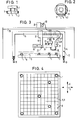
- Pallets are used for the production of precast concrete parts, in particular precast concrete ceiling segments, on which the concrete, after the arrangement and fixing of the built-in parts 1, is introduced at predetermined locations on the upper side 9 thereof in a manner not shown. 3 and 4, a pallet 11 is shown in simplified form.
- a device 12 is used to position and fix the built-in parts 1 on the pallet 11 in a position-safe manner, the main parts of which are a gantry carrier 14 which can be moved horizontally in an X direction on rails 13 and which has a horizontal support beam 15, and one on the support beam 15 in a horizontal position perpendicular to the X.
- a gantry carrier 14 which can be moved horizontally in an X direction on rails 13 and which has a horizontal support beam 15, and one on the support beam 15 in a horizontal position perpendicular to the X.
- Direction extending Y direction slidable carriage 16 a gripper 17 mounted on the carriage 16 and movable in the vertical Z direction with gripping jaws 18, a feed device 19 for built-in parts 1 held on the carriage 16 and an application device 21 preferably also held on the carriage 16 are glue.
- the pallet 11 is located under the device 12 in the range of movement of the gripper 17, whereby according to the X and Y coordinates are aligned horizontally.
- the dimensions of the device are so large that the gripper can cover the entire top 9 of the pallet 11. B on the pallet 11 in the installation position indicated reinforcement mats.
- the feed device 19 for built-in parts 1 has an indicated magazine 22 for built-in parts 1, from which the built-in parts 1 reach a standby point 23 by means of a device, not shown, for example due to gravity.
- a slide device 24 which is indicated on the feed device 19 and is indicated, with which a built-in part 1 transported to the standby point 23 can be individually displaced horizontally to a takeover point 25 arranged under the gripper 17.
- the installation part 1 in question can be gripped by lowering the gripper 17 and actuating the gripping jaws 18, after which the slide device 24 is then moved back into its starting position.
- the application device 21 is horizontally between a standby position, in which its spray gun or its spray tube 26 is located outside the vertical movement path of the gripper 17, and an order position shown in FIG. 3, in which the mouth of the spray tube 26 from below onto the standing surface 3 of the mounting part 1 is directed, horizontally displaceably held on a holder 21a.
- the application device 21 is moved into its retracted starting position. Then the gripper 17 is lowered and the mounting part 1 is placed on the top 9 of the pallet 11 in the desired position, where the hardening adhesive fixes the mounting part 1 on the top 9.
- an adhesive that is used after a certain time its adhesive strength is reduced, so that after the concrete has hardened, the pallet 11 can be easily detached from the built-in parts 1 embedded in the concrete.
- Such an adhesive is available under the name EVA 516 from Heinrichphaln KG.
- the individual work steps of the device 12 are automatically controlled by means of an electrical control device (not shown).
- the control device is assigned a computer which makes it possible to approach predeterminable arrangement points for the built-in parts 1.
- the control device is assigned distance meters for the respective distances traveled, depending on an O position. Since the pallet 11 also has a specific assignment to this O point, the arrangement points on the pallet 1 can be predetermined and safely approached.
- the adhesive of the application device 21 is fed through a heatable supply hose 27, through which the adhesive is fed from an adhesive preparation station 28, which is preferably located on a stationary stage 29 arranged above the device 12, in particular in a respect to the Pallet 11 or in the middle position with respect to the horizontal movement range of the gripper 17, so that all possible arrangement locations for built-in parts 1 can be approached with the smallest possible hose length.
- the feed hose 27 can preferably also be wound on a roll 30 or the like arranged on the stage 29 or on the application device 21, so that its required length can be adapted in each case.
- an adhesive preparation station 28 one or more storage containers for finished or component adhesives can also be provided.
- the gripper 17 is preferably about its vertical central axis actively rotatable, especially through 360 °. Such mobility makes it possible to apply an adhesive in the form of a ring 31 to the underside of the respective mounting part 1.
- the mouth of the spray tube 26 is placed in a position eccentric with respect to the vertical central axis of the gripper 17.
- the gripper 17 is rotated horizontally with the installation part 1 in question, so that the desired annular adhesive application is created automatically.
- a ring-shaped adhesive application 31 is advantageous in comparison with an adhesive application at several points, which can also be carried out with the device 12, because the spray tube 26 only has to be attached and removed or opened and closed with each adhesive application. This significantly reduces the risk of unwanted soiling from glue.
- one or more built-in components 1 penetrate an existing reinforcement mat B in the area of a reinforcement bar and thus interrupt the at least one reinforcement bar to use a computer programmed in such a way that it calculates the above-described weakening of the reinforcement mat and automatically takes into account or displays a reinforcement of this reinforcement mat B. This is particularly advantageous for a semi or fully automatic production with semi or fully automatic feeding of the reinforcement mesh.
Landscapes
- Engineering & Computer Science (AREA)
- Manufacturing & Machinery (AREA)
- Chemical & Material Sciences (AREA)
- Ceramic Engineering (AREA)
- Mechanical Engineering (AREA)
- Conveying And Assembling Of Building Elements In Situ (AREA)
Applications Claiming Priority (2)
| Application Number | Priority Date | Filing Date | Title |
|---|---|---|---|
| DE4031384 | 1990-10-04 | ||
| DE19904031384 DE4031384C1 (fr) | 1990-10-04 | 1990-10-04 |
Publications (2)
| Publication Number | Publication Date |
|---|---|
| EP0479129A2 true EP0479129A2 (fr) | 1992-04-08 |
| EP0479129A3 EP0479129A3 (en) | 1993-03-31 |
Family
ID=6415569
Family Applications (1)
| Application Number | Title | Priority Date | Filing Date |
|---|---|---|---|
| EP19910116435 Withdrawn EP0479129A3 (en) | 1990-10-04 | 1991-09-26 | Apparatus and process for locating and securing inserts on a shuttering for making concrete prefabricated building elements |
Country Status (2)
| Country | Link |
|---|---|
| EP (1) | EP0479129A3 (fr) |
| DE (1) | DE4031384C1 (fr) |
Families Citing this family (6)
| Publication number | Priority date | Publication date | Assignee | Title |
|---|---|---|---|---|
| DE4129368C2 (de) * | 1991-09-04 | 1997-09-11 | Weckenmann Anlagentechnik Gmbh | Einrichtung zur Herstellung von Betonfertigteilen |
| ITTV20060004A1 (it) * | 2006-01-20 | 2007-07-21 | Luca Toncelli | Procedimento per la fabbricazione di manufatti in forma di lastra a base di materiale lapideo o litoide e relativi manufatti |
| AT517094B1 (de) * | 2015-08-17 | 2016-11-15 | Progress Holding Ag | Abstützverfahren zur Abstützung einer Bewehrungskonstruktion |
| DE102019200401A1 (de) * | 2019-01-15 | 2020-07-16 | Herbert Wintersteiger | Verfahren und Vorrichtung zur Positionierung von Betoneinbauelementen auf einer Schalungsunterlage, sowie Betoneinbauelement zur Verwendung in Kombination mit der Vorrichtung |
| DE102019200400A1 (de) * | 2019-01-15 | 2020-07-16 | Herbert Wintersteiger | Verfahren und Vorrichtung zur Positionierung und/oder Entfernung von Fixierungselementen auf/von einer Schalungsunterlage, sowie Fixierungselement zur Verwendung in Kombination mit der Vorrichtung, sowohl einzeln als auch in Kombination als System |
| DE102023128688A1 (de) * | 2023-10-19 | 2025-04-24 | Thomas Wintersteiger | Vorrichtung und Verfahren zum Absetzen und/oder Abheben von Fixierungsmagneten auf/von einer Schalungsunterlage mit einem Magnetmagazin mit mehreren unabhängigen Magnetaufnahmen |
Family Cites Families (7)
| Publication number | Priority date | Publication date | Assignee | Title |
|---|---|---|---|---|
| DE1918965A1 (de) * | 1969-04-15 | 1970-11-12 | Heinrich Geisel | Anordnung und Vorrichtung zum Anordnen der Verankerungsoesen bei Kunststeineinfassungen |
| DE2740032A1 (de) * | 1977-09-06 | 1979-03-08 | Hans Ing Grad Katheder | Verfahren und vorrichtung zum zufuehren und einsetzen von buegelfoermig gebogenen draehten in formlinge oder bauteile |
| DE3420806A1 (de) * | 1984-06-04 | 1985-12-05 | Hugo 8831 Dollnstein Bittlmayer | Verfahren zum bewehren von betonplatten sowie vorrichtung zur durchfuehrung des verfahrens |
| DE3519562A1 (de) * | 1985-06-11 | 1986-12-04 | PTX-Pentronix, Inc., Lincoln Park, Mich. | Vorrichtung zur uebertragung von teilen |
| US4753412A (en) * | 1987-02-24 | 1988-06-28 | American Institute Of Taxidermy, Inc. | Taxidermy mannikin mold for locating eyepieces in correct position |
| CH677382A5 (fr) * | 1988-11-25 | 1991-05-15 | Constral Ag | |
| FR2666052A1 (fr) * | 1990-08-21 | 1992-02-28 | Brault Benoit | Dispositif et procede de decoration de materiaux ceramiques. |
-
1990
- 1990-10-04 DE DE19904031384 patent/DE4031384C1/de not_active Expired - Lifetime
-
1991
- 1991-09-26 EP EP19910116435 patent/EP0479129A3/de not_active Withdrawn
Also Published As
| Publication number | Publication date |
|---|---|
| DE4031384C1 (fr) | 1992-01-30 |
| EP0479129A3 (en) | 1993-03-31 |
Similar Documents
| Publication | Publication Date | Title |
|---|---|---|
| DE4010024B4 (de) | Fertigungsanlage mit Parallel- und Nebenförderwegen | |
| DE3223474C2 (de) | Vorrichtung zum automatischen Montieren von Geräten | |
| DE3715927C2 (fr) | ||
| EP1075347A1 (fr) | Installation pour positionner et souder des elements de carrosserie de differents types d'automobiles | |
| DE3613956A1 (de) | Montageanlage zum zusammenbau von teilen | |
| DE3542496A1 (de) | Verfahren und vorrichtung zum zufuehren von montageteilen | |
| DE10333334A1 (de) | Anordnung und Verfahren zur Aufnahme und zum Transport von Pfosten eines Leitplankensystems | |
| DE4031384C1 (fr) | ||
| EP3665711A1 (fr) | Dispositif et procédé de fabrication de noyaux de transformateur | |
| EP3672763B1 (fr) | Système et procédé de positionnement et de serrage | |
| EP2524861B1 (fr) | Dispositif et procédé de manipulation d'un support d'outil de montage de véhicule sur une ligne de fabrication de véhicule, support d'outil de montage de véhicule et station de montage | |
| DE202020006118U1 (de) | Vorrichtung zur Entfernung von Fixierungselementen von einer Schalungsunterlage | |
| DE4340818C2 (de) | Einspannvorrichtung für ein Werkstück | |
| DE19631630C2 (de) | Bearbeitungsmaschine mit einer Saugspanneinrichtung | |
| DE19509985A1 (de) | Verfahren zum Ausrüsten von Schienenauflagekörpern, insbesondere Beton- oder Spannbetonschwellen mit Schienenbefestigungsteilen sowie Matrize zur Durchführung des Verfahrens | |
| EP1854630A2 (fr) | Dispositif de revêtement ou de flocage des objects, notamment des materiaux textils avec pochoir | |
| EP1587987A1 (fr) | Procede d'installation d'un element prefabrique et dispositif de reception de prismes de mesure | |
| WO2015071013A1 (fr) | Machine-outil cnc | |
| DE874363C (de) | Einrichtung zum Zulegen von Formkaesten | |
| DE4320257C2 (de) | Verfahren zum Aufbringen von Dichtungen mit definiertem Querschnitt auf Gegenstände | |
| EP1663571A1 (fr) | Ensemble de support pour dispositifs de serrage presentant une bride de connexion qui permet la connexion a un robot | |
| DE4427251C2 (de) | Presse, insbesondere Ziegelpresse | |
| DE1602912B2 (de) | Verfahren zum Positionieren eines Werkstückes auf dem Werkstücktisch einer Werkzeugmaschine und Vorrichtung zur Durchführung dieses Verfahrens | |
| DE3302273C1 (de) | Montageeinrichtung mit einem kontinuierlich bewegten Transferband | |
| DE19538891C2 (de) | Verfahren und Vorrichtung zum großflächigen horizontalen Verlegen von Platten |
Legal Events
| Date | Code | Title | Description |
|---|---|---|---|
| PUAI | Public reference made under article 153(3) epc to a published international application that has entered the european phase |
Free format text: ORIGINAL CODE: 0009012 |
|
| AK | Designated contracting states |
Kind code of ref document: A2 Designated state(s): AT BE CH DE DK FR GB IT LI LU NL SE |
|
| PUAL | Search report despatched |
Free format text: ORIGINAL CODE: 0009013 |
|
| AK | Designated contracting states |
Kind code of ref document: A3 Designated state(s): AT BE CH DE DK FR GB IT LI LU NL SE |
|
| 17P | Request for examination filed |
Effective date: 19930930 |
|
| 17Q | First examination report despatched |
Effective date: 19950224 |
|
| STAA | Information on the status of an ep patent application or granted ep patent |
Free format text: STATUS: THE APPLICATION IS DEEMED TO BE WITHDRAWN |
|
| 18D | Application deemed to be withdrawn |
Effective date: 19960402 |