EP0479129A2 - Apparatus and process for locating and securing inserts on a shuttering for making concrete prefabricated building elements - Google Patents
Apparatus and process for locating and securing inserts on a shuttering for making concrete prefabricated building elements Download PDFInfo
- Publication number
- EP0479129A2 EP0479129A2 EP91116435A EP91116435A EP0479129A2 EP 0479129 A2 EP0479129 A2 EP 0479129A2 EP 91116435 A EP91116435 A EP 91116435A EP 91116435 A EP91116435 A EP 91116435A EP 0479129 A2 EP0479129 A2 EP 0479129A2
- Authority
- EP
- European Patent Office
- Prior art keywords
- adhesive
- built
- pallet
- gripper
- coordinate
- Prior art date
- Legal status (The legal status is an assumption and is not a legal conclusion. Google has not performed a legal analysis and makes no representation as to the accuracy of the status listed.)
- Withdrawn
Links
Images
Classifications
-
- B—PERFORMING OPERATIONS; TRANSPORTING
- B28—WORKING CEMENT, CLAY, OR STONE
- B28B—SHAPING CLAY OR OTHER CERAMIC COMPOSITIONS; SHAPING SLAG; SHAPING MIXTURES CONTAINING CEMENTITIOUS MATERIAL, e.g. PLASTER
- B28B23/00—Arrangements specially adapted for the production of shaped articles with elements wholly or partly embedded in the moulding material; Production of reinforced objects
- B28B23/0056—Means for inserting the elements into the mould or supporting them in the mould
Definitions
- the invention relates to an apparatus and a method according to the preamble of claims 1 and 14, respectively.
- Such built-in parts can be supporting elements on which the hardened prefabricated concrete components can be transported and handled, or it can also be fastening parts with prefabricated fastening elements, in particular holes, on which the prefabricated concrete components are connected to one another or to other components during assembly, e.g. can be screwed.
- a built-in part has a flat position surface, particularly when producing concrete slabs, with which it is placed on the pallet. In the finished precast concrete element, this position area is located on the surface of the precast concrete element. The body of the built-in part protruding into the concrete is undercut so that the built-in part is held in a form-fitting manner in the hardened concrete.
- a built-in part is formed by two plates connected to one another by a central pin, the outer plate, ie the plate having the position surface, being round and the inner plate completely surrounded by concrete being square.
- the built-in parts have a fastening hole, preferably a threaded hole, particularly in the center of the position surface, which is used for the above-described fastening of supporting elements or other components, such as rails or neighboring prefabricated concrete components.
- a fastening hole preferably a threaded hole, particularly in the center of the position surface, which is used for the above-described fastening of supporting elements or other components, such as rails or neighboring prefabricated concrete components.
- accurate positioning of the mounting part is required to have the mounting hole in a predetermined position.
- the invention has for its object to provide a device with which the built-in parts can be easily and quickly arranged and fixed at predetermined locations.
- the built-in parts can be arranged and fixed semi-automatically or fully automatically, so that this can be carried out quickly and safely with little or no handling.
- the installation parts are fed automatically in the vicinity of the gripper, so that the installation parts can be distributed and arranged with little transport effort.
- the fixtures are fixed on the surface of the pallet by gluing, which can be carried out quickly and effectively. The gluing takes place automatically.
- Another significant advantage of the device according to the invention is that, due to the automatic control according to predetermined control criteria and simultaneous monitoring of the control paths, incorrect arrangement of built-in parts is practically impossible. This can happen with a manual arrangement, however, happen relatively quickly, for example if the operator makes a measurement error.
- the adhesive can be applied parallel to the function of the gripper, which means that additional manufacturing time can be saved.
- the adhesive can be applied at the ready position at which the built-in part to be gripped is ready.
- simpler devices can be realized since the movement of the gripper can be used to carry out a flat job.
- the built-in part 1 has a laterally undercut body 2 with a flat base 3 on the underside, in the center of which a threaded bore 4, which is arranged in the body 2 and runs perpendicular to the base 3, opens out.
- the body 2 consists of a lower round plate 5, a pin 6 arranged on the lower plate 5, the cross-sectional dimension of which is tapered compared to the cross-sectional dimension of the lower plate 5, and an upper, preferably square plate 7 on the pin 6.
- By the waist in Pin 6 is an undercut, which allows a positive embedding of the built-in part 1 in the concrete. Due to the square shape of the top plate 7, a positive rotation lock for the built-in part 1 is also created about its vertical central axis.
- Pallets are used for the production of precast concrete parts, in particular precast concrete ceiling segments, on which the concrete, after the arrangement and fixing of the built-in parts 1, is introduced at predetermined locations on the upper side 9 thereof in a manner not shown. 3 and 4, a pallet 11 is shown in simplified form.
- a device 12 is used to position and fix the built-in parts 1 on the pallet 11 in a position-safe manner, the main parts of which are a gantry carrier 14 which can be moved horizontally in an X direction on rails 13 and which has a horizontal support beam 15, and one on the support beam 15 in a horizontal position perpendicular to the X.
- a gantry carrier 14 which can be moved horizontally in an X direction on rails 13 and which has a horizontal support beam 15, and one on the support beam 15 in a horizontal position perpendicular to the X.
- Direction extending Y direction slidable carriage 16 a gripper 17 mounted on the carriage 16 and movable in the vertical Z direction with gripping jaws 18, a feed device 19 for built-in parts 1 held on the carriage 16 and an application device 21 preferably also held on the carriage 16 are glue.
- the pallet 11 is located under the device 12 in the range of movement of the gripper 17, whereby according to the X and Y coordinates are aligned horizontally.
- the dimensions of the device are so large that the gripper can cover the entire top 9 of the pallet 11. B on the pallet 11 in the installation position indicated reinforcement mats.
- the feed device 19 for built-in parts 1 has an indicated magazine 22 for built-in parts 1, from which the built-in parts 1 reach a standby point 23 by means of a device, not shown, for example due to gravity.
- a slide device 24 which is indicated on the feed device 19 and is indicated, with which a built-in part 1 transported to the standby point 23 can be individually displaced horizontally to a takeover point 25 arranged under the gripper 17.
- the installation part 1 in question can be gripped by lowering the gripper 17 and actuating the gripping jaws 18, after which the slide device 24 is then moved back into its starting position.
- the application device 21 is horizontally between a standby position, in which its spray gun or its spray tube 26 is located outside the vertical movement path of the gripper 17, and an order position shown in FIG. 3, in which the mouth of the spray tube 26 from below onto the standing surface 3 of the mounting part 1 is directed, horizontally displaceably held on a holder 21a.
- the application device 21 is moved into its retracted starting position. Then the gripper 17 is lowered and the mounting part 1 is placed on the top 9 of the pallet 11 in the desired position, where the hardening adhesive fixes the mounting part 1 on the top 9.
- an adhesive that is used after a certain time its adhesive strength is reduced, so that after the concrete has hardened, the pallet 11 can be easily detached from the built-in parts 1 embedded in the concrete.
- Such an adhesive is available under the name EVA 516 from Heinrichphaln KG.
- the individual work steps of the device 12 are automatically controlled by means of an electrical control device (not shown).
- the control device is assigned a computer which makes it possible to approach predeterminable arrangement points for the built-in parts 1.
- the control device is assigned distance meters for the respective distances traveled, depending on an O position. Since the pallet 11 also has a specific assignment to this O point, the arrangement points on the pallet 1 can be predetermined and safely approached.
- the adhesive of the application device 21 is fed through a heatable supply hose 27, through which the adhesive is fed from an adhesive preparation station 28, which is preferably located on a stationary stage 29 arranged above the device 12, in particular in a respect to the Pallet 11 or in the middle position with respect to the horizontal movement range of the gripper 17, so that all possible arrangement locations for built-in parts 1 can be approached with the smallest possible hose length.
- the feed hose 27 can preferably also be wound on a roll 30 or the like arranged on the stage 29 or on the application device 21, so that its required length can be adapted in each case.
- an adhesive preparation station 28 one or more storage containers for finished or component adhesives can also be provided.
- the gripper 17 is preferably about its vertical central axis actively rotatable, especially through 360 °. Such mobility makes it possible to apply an adhesive in the form of a ring 31 to the underside of the respective mounting part 1.
- the mouth of the spray tube 26 is placed in a position eccentric with respect to the vertical central axis of the gripper 17.
- the gripper 17 is rotated horizontally with the installation part 1 in question, so that the desired annular adhesive application is created automatically.
- a ring-shaped adhesive application 31 is advantageous in comparison with an adhesive application at several points, which can also be carried out with the device 12, because the spray tube 26 only has to be attached and removed or opened and closed with each adhesive application. This significantly reduces the risk of unwanted soiling from glue.
- one or more built-in components 1 penetrate an existing reinforcement mat B in the area of a reinforcement bar and thus interrupt the at least one reinforcement bar to use a computer programmed in such a way that it calculates the above-described weakening of the reinforcement mat and automatically takes into account or displays a reinforcement of this reinforcement mat B. This is particularly advantageous for a semi or fully automatic production with semi or fully automatic feeding of the reinforcement mesh.
Landscapes
- Engineering & Computer Science (AREA)
- Manufacturing & Machinery (AREA)
- Chemical & Material Sciences (AREA)
- Ceramic Engineering (AREA)
- Mechanical Engineering (AREA)
- Conveying And Assembling Of Building Elements In Situ (AREA)
Abstract
Es ist eine Vorrichtung (12) zum lagesicheren Anordnen von Einbauteilen (1) auf einer Palette (11) für die Fertigung von Betonfertigbauteilen zu schaffen, mit der die Einbauteile (1) leicht und schnell an vorbestimmten Stellen angeordnet und fixiert werden können. Dies wird durch einen längs einer X-Koordinate parallel zu einer Seite der Palette (11) bewegbaren Träger (15), einen längs des Trägers (15) und dabei längs einer Y-Koordinate senkrecht zur X-Koordinate bewegbaren Schlitten (16), einen Greifer (17) an dem Schlitten (16), der längs einer zu den X- und Y-Koordinaten senkrechten Z-Koordinate auf die Palette (11) zu bzw. von dieser weg bewegbar ist, einer Zuführeinrichtung (19) am Schlitten (16) zur Zufuhr einzelner Einbauteile (1) und einer Klebstoffzuführeinrichtung (26) zum Zuführen und ganz oder teilweisen Auftragen von Klebstoff auf der auf die Palette (11) abzu- setzenden Fläche (3) des Einbauteils (1), wobei der Greifer (17) durch Bewegung in der Z-Koordinatenrichtung dieses Einbauteil (1) mit der mit Klebstoff beschichteten Fläche (3) auf die Palette (11) unter Ausübung von Druck an einer durch Bewegung längs der X- und der Y-Koordinaten bestimmten Stelle absetzt. Die Erfindung bezieht sich auch auf ein Verfahren zum lagesicheren Anordnen von Einbauteilen (1) auf eine Palette (11).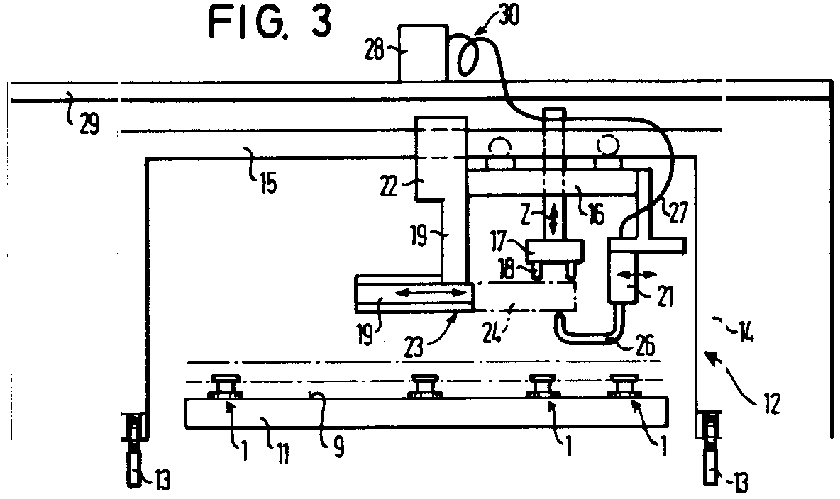
Description
Die Erfindung bezieht sich auf eine Vorrichtung und ein Verfahren nach dem Oberbegriff des Anspruchs 1 bzw. 14.The invention relates to an apparatus and a method according to the preamble of
Bei der Herstellung von Betonfertigbauteilen ist es aus verschiedenen Gründen erforderlich, Einbauteile darin anzuordnen, die vor dem Betonieren lagesicher angeordnet werden müssen. Bei solchen Einbauteilen kann es sich um Tragelemente handeln, an denen die erhärteten Betonfertigbauteile transportiert und gehandhabt werden können, oder es kann sich auch um Befestigungsteile mit vorgefertigten Befestigungselementen, insbesondere Löchern handeln, an denen die Betonfertigbauteile bei der Montage miteinander oder mit weiteren Bauteilen verbunden, z.B. verschraubt, werden können.For the manufacture of precast concrete components, it is necessary for various reasons to arrange built-in components that must be arranged in a secure position before concreting. Such built-in parts can be supporting elements on which the hardened prefabricated concrete components can be transported and handled, or it can also be fastening parts with prefabricated fastening elements, in particular holes, on which the prefabricated concrete components are connected to one another or to other components during assembly, e.g. can be screwed.
Ein Einbauteil weist insbesondere bei der Herstellung von Betonplatten eine ebene Positionsfläche auf, mit der es auf die Palette aufgesetzt wird. Beim fertigen Betonfertigbauteil befindet sich diese Positionsfläche an der Oberfläche des Betonfertigbauteils. Der in den Beton hineinragende Körper des Einbauteils ist hinterschnitten geformt, so daß das Einbauteil im erhärteten Beton formschlüssig gehalten ist. Ein Einbauteil wird durch zwei durch einen zentralen Zapfen miteinander verbundene Platten gebildet, wobei die äußere Platte, d.h. die die Posititonsfläche aufweisende Platte rund und die vom Beton völlig umgebene innere Platte viereckig geformt ist. In den meisten Fällen weisen die Einbauteile ein, insbesondere zentral in der Positionsfläche ausnehmendes Befestigungsloch, vorzugsweise Gewindeloch, auf, das der vorbeschriebenen Befestigung von Tragelementen oder weiteren Bauteilen wie z.B. Schienen oder benachbarten Betonfertigbauteilen dient. Insbesondere bei einem Einbauteil mit einem Befestigungsloch ist eine genaue Positionierung des Einbauteils erforderlich, um das Befestigungsloch in einer vorbestimmten Position vorliegen zu haben.A built-in part has a flat position surface, particularly when producing concrete slabs, with which it is placed on the pallet. In the finished precast concrete element, this position area is located on the surface of the precast concrete element. The body of the built-in part protruding into the concrete is undercut so that the built-in part is held in a form-fitting manner in the hardened concrete. A built-in part is formed by two plates connected to one another by a central pin, the outer plate, ie the plate having the position surface, being round and the inner plate completely surrounded by concrete being square. In most cases, the built-in parts have a fastening hole, preferably a threaded hole, particularly in the center of the position surface, which is used for the above-described fastening of supporting elements or other components, such as rails or neighboring prefabricated concrete components. Especially in the case of an installation part with a fastening hole accurate positioning of the mounting part is required to have the mounting hole in a predetermined position.
Bisher ist es üblich, die Einbauteile vor dem Betonieren an den erforderlichen Stellen von Rand einzulegen. Dies ist mit einem erheblichen Aufwand verbunden, weil insbesondere größere Einbauteile ein erhebliches Gewicht aufweisen und das Anordnen mit einem erheblichen Zeitaufwand verbunden ist. Letzteres ist u.a. dadurch bedingt, daß die Einbauteile in den bestimmten Positionen ausgemessen und ausgerichtet werden müssen. Auch die Fixierung der Einbauteile in den ausgerichteten Positionen ist mit einem erheblichen Arbeits- und Zeitaufwand verbunden.So far, it has been customary to insert the installation parts from the edge at the required points before concreting. This is associated with a considerable effort because, in particular, larger built-in parts have a considerable weight and the arrangement takes a considerable amount of time. The latter is among others due to the fact that the built-in parts must be measured and aligned in the specific positions. The fixation of the built-in parts in the aligned positions is also associated with a considerable amount of work and time.
Der Erfindung liegt die Aufgabe zugrunde, eine Vorrichtung zu schaffen, mit der die Einbauteile leicht und schnell an vorbestimmten Stellen angeordnet und fixiert werden können.The invention has for its object to provide a device with which the built-in parts can be easily and quickly arranged and fixed at predetermined locations.
Diese Aufgabe wird durch die Merkmale des Anspruchs 1 bzw. 14 gelöst.This object is solved by the features of
Bei der erfindungsgmäßen Vorrichtung und dem erfindungsgemäßen Verfahren lassen sich die Einbauteile halb- oder vollautomatisch anordnen und fixieren, so daß dies mit keinem oder nur geringem Handhabungsaufwand schnell und sicher durchgeführt werden kann. Dabei erfolgt das Zuführen der Einbauteile automatisch, in der Nähe des Greifers, so daß die Einbauteile mit einem geringen Transportaufwand verteilt und angeordnet werden können. Die Fixierung der Einbauteile auf der Oberfläche der Palette erfolgt durch Kleben, was sich schnell und wirksam durchführen läßt. Dabei erfolgt auch das Kleben automatisch. Ein weiterer wesentlicher Vorteil der erfindungsgemäßen Vorrichtung besteht darin, daß aufgrund der automatischen Steuerung nach vorgegebenen Steuerungskriterien und gleichzeitiger Überwachung der Steuerungswege ein falsches Anordnen von Einbauteilen praktisch ausgeschlossen ist. Dies kann bei einer manuellen Anordnung jedoch verhältnismäßig schnell passieren, z.B. dann, wenn der Bedienungsperson ein Meßfehler unterläuft.With the device according to the invention and the method according to the invention, the built-in parts can be arranged and fixed semi-automatically or fully automatically, so that this can be carried out quickly and safely with little or no handling. The installation parts are fed automatically in the vicinity of the gripper, so that the installation parts can be distributed and arranged with little transport effort. The fixtures are fixed on the surface of the pallet by gluing, which can be carried out quickly and effectively. The gluing takes place automatically. Another significant advantage of the device according to the invention is that, due to the automatic control according to predetermined control criteria and simultaneous monitoring of the control paths, incorrect arrangement of built-in parts is practically impossible. This can happen with a manual arrangement, however, happen relatively quickly, for example if the operator makes a measurement error.
In den Unteransprüchen sind Merkmale enthalten, die in weiterer Ausbildung zur Lösung des der Erfindung zugrunde liegenden Problems beitragen und außerdem auch aus anderen Gründen vorteilhaft sind, wie z.B. zu einer einfachen und kostengünstigen Bauweise führen und dabei eine sichere Funktion gewährleisten.Features are contained in the subclaims which contribute to solving the problem on which the invention is based and which are also advantageous for other reasons, such as e.g. lead to a simple and inexpensive construction and thereby ensure a safe function.
Es ist im Rahmen der Erfindung möglich, den Auftrag des Klebers vor dem Ergreifen des jeweiligen Einbauteils mit dem Greifer oder nach dem Ergreifen auszuführen. Im ersteren Fall kann der Kleberauftrag parallel zu der Funktion des Greifers erfolgen, wodurch weitere Fertigungszeit eingespart werden kann. Dabei kann der Kleberauftrag an der Bereitstellungsposition erfolgen, an der das vom Greifer zu ergreifende Einbauteil bereitliegt. Im zweiten Fall lassen sich einfachere Vorrichtungen verwirklichen, da die Bewegung des Greifers dazu ausgenutzt werden kann, einen flächigen Auftrag auszuführen.It is possible within the scope of the invention to carry out the application of the adhesive with the gripper or after gripping the respective installation part. In the former case, the adhesive can be applied parallel to the function of the gripper, which means that additional manufacturing time can be saved. The adhesive can be applied at the ready position at which the built-in part to be gripped is ready. In the second case, simpler devices can be realized since the movement of the gripper can be used to carry out a flat job.
Nachfolgend wird die Erfindung anhand eines in einer Zeichnung dargestellten bevorzugten Ausführungsbeispiels näher erläutert.
Es zeigt:
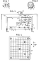
- Fig. 1
- ein Einbauteil für Betonfertigbauteile in der Seitenansicht;
- Fig. 2
- das Einbauteil in der Draufsicht;
- Fig. 3
- eine erfindungsgemäße Vorrichtung zum lagesicheren Anordnen von Einbauteilen auf eine Palette in der Vorderansicht;
- Fig. 4
- eine mit Einbauteilen besetzte Palette in der Draufsicht.
It shows:
- Fig. 1
- an installation part for precast concrete parts in side view;
- Fig. 2
- the installation part in plan view;
- Fig. 3
- a device according to the invention for the secure arrangement of built-in parts on a pallet in the front view;
- Fig. 4
- a pallet with built-in parts in plan view.
Das Einbauteil 1 weist einen seitlich hinterschnittenen Körper 2 mit einer unterseitigen ebenen Standfläche 3 auf, in deren Zentrum eine im Körper 2 angeordnete senkrecht zur Standfläche 3 verlaufende Gewindebohrung 4 ausmündet. Der Köper 2 besteht aus einer unteren runden Platte 5, einem auf der unteren Platte 5 angeordneten Zapfen 6, dessen Querschnittabmessung gegenüber der Querschnittsabmessung der unteren Platte 5 verjüngt ist, und einer oberen, vorzugsweise viereckigen Platte 7 auf dem Zapfen 6. Durch die Taillierung im Zapfen 6 ist eine Hinterschneidung vorgegeben, die eine formschlüssige Einbettung des Einbauteils 1 im Beton ermöglicht. Aufgrund der viereckigen Form der oberen Platte 7 ist außerdem eine formschlüssige Drehsicherung für das Einbauteil 1 um seine vertikale Mittelachse geschaffen.The built-in part 1 has a laterally undercut body 2 with a flat base 3 on the underside, in the center of which a
Zur Fertigung von Betonfertigteilen, insbesondere Fertigbetondeckensegmenten dienen Paletten, auf denen der Beton nach der Anordnung und Fixierung der Einbauteile 1 an vorgegebenen Stellen auf deren Oberseite 9 in nicht dargestellter Weise eingebracht wird. In den Fig. 3 und 4 ist eine Palette 11 vereinfacht dargestellt.Pallets are used for the production of precast concrete parts, in particular precast concrete ceiling segments, on which the concrete, after the arrangement and fixing of the built-in parts 1, is introduced at predetermined locations on the
Zum lagesicheren Anordnen und Fixieren der Einbauteile 1 auf der Palette 11 dient eine Vorrichtung 12, deren Hauptteile ein auf Schienen 13 horizontal in einer X-Richtung verfahrbarer Portalträger 14 mit einem horizontalen Tragbalken 15, ein am Tragbalken 15 in eine horizontale, sich rechtwinklig zur X-Richtung erstreckende Y-Richtung verschiebbarer Schlitten 16, ein am Schlitten 16 gelagerter, in der vertikalen Z-Richtung bewegbarer Greifer 17 mit Greifbacken 18, eine am Schlitten 16 gehaltene Zuführungsvorrichtung 19 für Einbauteile 1 und eine vorzugsweise ebenfalls am Schlitten 16 gehaltene Auftragsvorrichtung 21 für Kleber sind.A
Die Palette 11 befindet sich unter der Vorrichtung 12 im Bewegungsbereich des Greifers 17, wobei sie nach den X- und Y-Koordinaten horizontal ausgerichtet ist. Die Abmessungen der Vorrichtung sind so große bemessen, daß der Greifer die gesamte Oberseite 9 der Palette 11 zu bestreichen vermag. Mit B sind auf der Palette 11 in Einbauposition angedeutete Bewehrungsmatten bezeichnet.The pallet 11 is located under the
Die Zuführungsvorrichtung 19 für Einbauteile 1 weist ein andeutungsweise dargestelltes Magazin 22 für Einbauteile 1 auf, aus dem die Einbauteile 1 mittels einer nicht näher dargestellten Einrichtung, z.B. aufgrund der Schwerkraft, zu einer Bereitschaftsstelle 23 gelangen. An der Bereitschaftsstelle 23 ist eine an der Zuführungsvorrichtung 19 gehaltene, andeutungsweise dargestellte Schiebervorrichtung 24 vorgesehen, mit der ein zur Bereitschaftsstelle 23 transportiertes Einbauteil 1 vereinzelt horizontal zur einer unter dem Greifer 17 angeordneten Übernahmestelle 25 verschoben werden kann. An der Übernahmestelle 25 kann das betreffende Einbauteil 1 durch Absenken des Greifers 17 und Betätigung der Greifbacken 18 ergriffen werden, wonach dann die Schiebervorrichtung 24 in ihre Ausgangsposition zurückbewegt wird. An der Übernahmestelle 25 wird von unten Kleber stellenweise auf die Standfläche 3 des vorhandenen Einbauteils 1 aufgetragen, insbesondere aufgesprüht. Hierzu ist die Auftragsvorrichtung 21 horizontol zwischen einer Bereitschaftsstellung, in der ihre Sprühpistole bzw. ihr Sprührohr 26 sich außerhalb der vertikalen Bewegungsbahn des Greifers 17 befindet und einer in Fig. 3 dargestellten Auftragsstellung, in der die Mündung des Sprührohrs 26 von unten auf die Standfläche 3 des Einbauteils 1 gerichtet ist, horizontal verschiebbar an einem Halter 21a gehalten. Nach dem Sprühvorgang des Klebers auf die Standfläche 3 wird die Auftragsvorrichtung 21 in ihre zurückgezogene Ausgangsstellung verschoben. Dann wird der Greifer 17 abgesenkt und das Einbauteil 1 auf die Oberseite 9 der Palette 11 in der gewünschten Position aufgesetzt, wo der erhärtende Kleber das Einbauteil 1 auf der Oberseite 9 fixiert. Es handelt sich vorzugsweise um einen Kleber, der nach einer bestimmten Zeit seine Klebefestigkeit verringert, so daß nach dem Erhärten des Betons die Palette 11 von den in den Beton eingebetteten Einbauteilen 1 leicht abgelöst werden kann. Ein solcher Kleber ist unter der Bezeichnung EVA 516 von der Fa. Heinrich Bühnen KG erhältlich.The
Die einzelnen Arbeitsschritte der Vorrichtung 12 werden mittels einer nicht dargestellten elektrischen Steuereinrichtung automatisch gesteuert. Der Steuereinrichtung ist ein Rechner zugeordnet, der es ermöglicht, vorbestimmbare Anordnungsstellen für die Einbauteile 1 anzufahren. Der Steuereinrichtung sind Wegmesser für die jeweils zurückgelegten Wege in Abhängigkeit einer O-Stellung zugeordnet. Da die Palette 11 ebenfalls eine bestimmte Zuordnung zu dieser O-Stelle aufweist, können die Anordnungsstellen auf der Palette 1 vorbestimmt und sicher angefahren werden. Bei der vorliegenden Ausgestaltung wird der Kleber der Auftragsvorrichtung 21 durch einen beheizbaren Zuführungsschlauch 27 zugeführt, durch den der Kleber von einer Kleberzubereitungsstation 28 zugeführt wird, die sich vorzugsweise auf einer oberhalb der Vorrichtung 12 angeordneten stationären Bühne 29 befindet, und zwar insbesondere in einer bezüglich der Palette 11 bzw. bezüglich des horizontalen Bewegungsbereichs des Greifes 17 mittleren Position, so daß mit einer möglichst geringen Schlauchlänge alle möglichen Anordnungsstellen für Einbauteile 1 angefahren werden können. Der Zuführungsschlauch 27 ist vorzugsweise auch auf einer auf der Bühne 29 oder an der Auftragsvorrichtung 21 angeordneten Rolle 30 oder dgl. aufwickelbar, so daß seine erforderliche Länge jeweils angepaßt werden kann. Anstelle einer Kleber-Zubereitungsstation 28 kann auch ein oder mehrere Vorratsbehälter für Fertig- oder Komponentenkleber vorgesehen sein.The individual work steps of the
Es ist im Rahmen der Erfindung auch möglich, die Kleber-Zubereitungsstation 28 oder einen Vorratsbehälter am Portalträger 14, am Schlitten 16 oder am Greifer 17 anzuordnen.It is also possible within the scope of the invention to arrange the
Vorzugsweise ist der Greifer 17 um seine vertikale Mittelachse aktiv drehbar, insbesondere um 360°. Eine solche Beweglichkeit ermöglicht es, einen Kleberauftrag in Form eines Ringes 31 an der Unterseite des jeweiligen Einbauteils 1 anzubringen. Hierzu wird die Mündung des Sprührohrs 26 in eine bezüglich der vertikalen Mittelachse des Greifers 17 exzentrische Position gestellt. Während des Sprühens wird der Greifer 17 mit dem betreffenen Einbauteil 1 horizontal gedreht, so daß der angestrebte ringförmige Kleberauftrag automatisch entsteht. Ein ringförmiger Kleberauftrag 31 ist im Vergleich mit einem Kleberauftrag an mehreren Punkten, was ebenfalls mit der Vorrichtung 12 durchführbar ist, vorteilhaft, weil das Sprührohr 26 bei jedem Kleberauftrag nur einmal an- und abgesetzt oder geöffnet und geschlossen zu werden braucht. Hierdurch ist die Gefahr von ungewollten Verschmutzungen durch Kleber wesentlich verringert.The gripper 17 is preferably about its vertical central axis actively rotatable, especially through 360 °. Such mobility makes it possible to apply an adhesive in the form of a
Um bei Gewährleistung der erforderlichen Bewehrung bzw. Festigkeit des Betonfertigbauteils so wenig wie möglich Bewehrungsmaterial zu verbrauchen, ist es vorteilhaft, in dem Fall, in dem ein oder mehrere Einbauteile 1 eine vorhandene Bewehrungsmatte B im Bereich eines Bewehrungsstabes durchsetzen und somit den wenigstens einen Bewehrungsstab unterbrechen, einen derart programmierten Rechner einzusetzen, daß dieser die vorbeschriebene Schwächung der Bewehrungsmatte berechnet und automatisch eine Verstärkung dieser Bewehrungsmatte B berücksichtigt bzw. anzeigt. Dies ist insbesondere für eine halb- oder vollautomatische Fertigung bei halb- oder vollautomatischer Zuführung der Bewehrungsmatten vorteilhaft.In order to use as little reinforcement material as possible while ensuring the required reinforcement or strength of the prefabricated concrete component, it is advantageous if one or more built-in components 1 penetrate an existing reinforcement mat B in the area of a reinforcement bar and thus interrupt the at least one reinforcement bar to use a computer programmed in such a way that it calculates the above-described weakening of the reinforcement mat and automatically takes into account or displays a reinforcement of this reinforcement mat B. This is particularly advantageous for a semi or fully automatic production with semi or fully automatic feeding of the reinforcement mesh.
Claims (17)
gekennzeichnet durch
einen längs einer X-Koordinate parallel zu einer Seite der Palette (11) bewegbaren Träger (15),
einen längs des Trägers (15) und dabei längs einer Y-Koordinate senkrecht zur X-Koordinate bewegbaren Schlitten (16),
einen Greifer (17) an dem Schlitten (16), der längs einer zu den X- und Y-Koordinaten senkrechten Z-Koordinate auf die Palette (11) zu bzw. von dieser weg bewegbar ist,
einer Zuführeinrichtung (19) am Schlitten (16) zur Zufuhr einzelner Einbauteile (1) und
einer Klebstoffzuführeinrichtung (26) zum Zuführen und ganz oder teilweisen Auftragen von Klebstoff auf der auf die Palette (11) abzusetzenden Fläche (3) des Einbauteils (1),
wobei der Greifer (17) durch Bewegung in der Z-Koordinatenrichtung dieses Einbauteil (1) mit der mit Klebstoff beschichteten Fläche (3) auf die Palette (11) unter Ausübung von Druck an einer durch Bewegung längs der X- und der Y-Koordinaten bestimmten Stelle absetzt.Device for the secure arrangement of built-in parts on a pallet for the manufacture of prefabricated concrete components, in particular prefabricated concrete ceiling elements,
characterized by
a carrier (15) movable along an X coordinate parallel to one side of the pallet (11),
a carriage (16) which can be moved along the support (15) and thereby along a Y coordinate perpendicular to the X coordinate,
a gripper (17) on the carriage (16), which can be moved towards or away from the pallet (11) along a Z coordinate perpendicular to the X and Y coordinates,
a feed device (19) on the carriage (16) for feeding individual installation parts (1) and
an adhesive supply device (26) for supplying and applying part or all of the adhesive on the surface (3) of the built-in part (1) to be placed on the pallet (11),
wherein the gripper (17) by moving in the Z coordinate direction of this mounting part (1) with the adhesive-coated surface (3) on the pallet (11) while exerting pressure on one by moving along the X and Y coordinates certain place.
dadurch gekennzeichnet,
daß die Einbauteil-Zuführeinrichtung (19) ein Vereinzelner ist.Device according to claim 1,
characterized by
that the built-in part feed device (19) is a single one.
dadurch gekennzeichnet,
daß der Einbauteil-Zuführungseinrichtung (11) eine Übertragungsvorrichtung (24) zum vorzugsweise horizontalen Übertragen eines Einbauteils (1) von einer Bereitschaftsstelle (23) zu einer vorzugsweise unter dem Greifer (17) befindlichen Übernahmestelle (25) zugeordnet ist.Device according to claim 1 or 2,
characterized by
that the built-in part feed device (11) is assigned a transmission device (24) for preferably horizontally transmitting a built-in part (1) from a standby point (23) to a takeover point (25) preferably located under the gripper (17).
dadurch gekennzeichnet,
daß der Einbauteil-Zuführeinrichtung (19) ein Magazin (22) für Einbauteile (1) zugeordnet ist.Device according to one or more of claims 1 to 3,
characterized by
that the built-in part feed device (19) is assigned a magazine (22) for built-in parts (1).
dadurch gekennzeichnet,
daß die Klebstoffzuführeinrichtung (21) den Klebstoff punktförmig, flächig oder ringförmig aufträgt, z.B. aufsprüht.Device according to one or more of claims 1 to 4,
characterized by
that the adhesive supply device (21) applies the adhesive in a punctiform, flat or ring-shaped manner, for example by spraying it on.
dadurch gekennzeichnet,
daß die Klebstoffzuführeinrichtung (21) ein dem Greifer zugeordnetes Schlauchsystem zur Zufuhr der Klebstoffkomponenten von einem oder mehreren ortsfesten Behältern oder einer Kleber-Zubereitungseinrichtung (28) aufweist.Device according to one or more of claims 1 to 5,
characterized by
that the adhesive supply device (21) has a hose system assigned to the gripper for supplying the adhesive components from one or more stationary containers or an adhesive preparation device (28).
dadurch gekennzeichnet,
daß die Klebstoffzuführeinrichtung (21) am Schlitten (16) angeordnet ist.Device according to one or more of claims 1 to 6,
characterized by
that the adhesive supply device (21) is arranged on the carriage (16).
dadurch gekennzeichnet,
daß die Klebstoffzuführeinrichtung (21) eine Sprühpistole oder ein Sprührohr (26) aufweist, deren bzw. dessen Mündungsöffnung vorzugsweise nach oben gerichtet ist.Device according to one or more of claims 1 to 7,
characterized by
that the adhesive feed device (21) has a spray gun or a spray tube (26), the orifice of which or the mouth is preferably directed upwards.
dadurch gekennzeichnet,
daß die Klebstoffzuführeinrichtung (21) zwischen einer Bereitschaftsstellung und einer Sprühstellung vorzugsweise horizontal bewegbar ist.Device according to one or more of claims 5 to 8,
characterized by
that the adhesive supply device (21) is preferably horizontally movable between a ready position and a spray position.
dadurch gekennzeichnet,
daß der Greifer (17) und die Klebstoffzuführeinrichtung (21) gegeneinander relativ bewegbar, insbesondere drehbewegbar, sind.Device according to one or more of claims 1 to 9,
characterized by
that the gripper (17) and the adhesive feed device (21) are relatively movable, in particular rotatable, relative to one another.
dadurch gekennzeichnet,
daß der Greifer (17) um seine vertikale Mittelachse vorzugsweise um 360° drehbar ist.Device according to claim 9 or 10,
characterized by
that the gripper (17) is preferably rotatable through 360 ° about its vertical central axis.
dadurch gekennzeichnet,
daß der Klebstoff schnellhaftend zum sicheren Verbinden eines Einbauteils (1) mit der Palette (11) bei Druckausübung ist und ferner nach dem Aushärten von aufgebrachtem Beton seine Haftkraft im wesentlichen verloren hat.Device according to one or more of claims 1 to 11,
characterized by
that the adhesive is fast-adhering for securely connecting a built-in part (1) to the pallet (11) when pressure is exerted and also has essentially lost its adhesive force after the applied concrete has hardened.
dadurch gekennzeichnet,
daß eine Recheneinrichtung zur Berechnung einer in das Betonfertigbauteil einzubringenden Bewehrungsmatte (B) die Lage eines Einbauteils (1) berücksichtigt, dessen Höhe in die in das Betonfertigbauteil eingebrachte Bewehrungsmatte (B) ragen könnte und an dieser Stelle eine Aussparung in der Bewehrungsmatte (B) annimmt.Device according to one or more of claims 1 to 12,
characterized by
that a computing device for calculating a reinforcement mat (B) to be inserted into the prefabricated concrete component takes into account the position of a built-in component (1), the height of which could protrude into the reinforcement mat (B) introduced into the prefabricated concrete component and at this point assumes a recess in the reinforcement mat (B) .
dadurch gekennzeichnet,
daß das aufzusetzende Einbauelement (1) mittels einer Einbauteil-Zuführeinrichtung (19), die mit einem Schlitten (16) längs einer X-Koordinate horizontal und parallel zu einer Seite der Paletten (11) sowie längs einer Y-Koordinate horizontal und senkrecht zur X-Koordinate bewegbar ist, an einer Übernahmestelle (25) bereitgestellt wird und mittels eines längs einer zu den X- und Y-Koordinaten senkrechten Z-Koordinate bewegbaren Greifers (17) ergriffen und an der gewünschten Anordnungsstelle auf der Palette (11) abgesetzt wird, wobei vor oder nach dem Ergreifen des Einbauteils (1) mit dem Greifer (17) mittels einer Klebstoffzuführeinrichtung (21) Klebstoff auf die auf die Palette (11) aufzusetzende Fläche (3) des Einbauteils (1) aufgetragen wird.Method for the secure arrangement of built-in parts on a pallet for the production of prefabricated concrete components, in particular prefabricated concrete ceiling elements, in which the built-in parts (1) are gripped at a removal point and transported and deposited to the associated arrangement point on the pallet (11), in particular with a device one or more of claims 1 to 13,
characterized by
that the mounting element to be fitted (1) by means of a built-in part feed device (19) which is horizontal and parallel to a side of the pallets (11) and along a Y coordinate with a slide (16) along an X coordinate Can be moved perpendicular to the X coordinate, is made available at a takeover point (25) and is gripped by means of a gripper (17) which can be moved along a Z coordinate perpendicular to the X and Y coordinates and at the desired arrangement point on the pallet (11) is discontinued, adhesive being applied to the surface (3) of the component (1) to be placed on the pallet (11) before or after gripping the component (1) with the gripper (17) by means of an adhesive supply device (21).
dadurch gekennzeichnet,
daß der Greifer (17) oder die Klebstoff-Zuführeinrichtung (19) beim Auftragen des Klebstoffs relativ zueinander bewegt werden.The method of claim 14
characterized by
that the gripper (17) or the adhesive feed device (19) are moved relative to one another when the adhesive is applied.
dadurch gekennzeichnet,
daß der Greifer (17) bei exentrischer Anordnung der Kleberzuführeinrichtung (26) an der Fläche (3) um seine vertikale Mittelachse vorzugsweise um 360° gedreht wird.A method according to claim 14 or 15,
characterized by
that the gripper (17) in the case of an eccentric arrangement of the adhesive feed device (26) on the surface (3) is preferably rotated through 360 ° about its vertical central axis.
dadurch gekennzeichnet,
daß der Kleber vorzugsweise von unten auf die Fläche (3) gesprüht wird.Method according to one or more of claims 14 to 16,
characterized by
that the adhesive is preferably sprayed onto the surface (3) from below.
Applications Claiming Priority (2)
| Application Number | Priority Date | Filing Date | Title |
|---|---|---|---|
| DE4031384 | 1990-10-04 | ||
| DE19904031384 DE4031384C1 (en) | 1990-10-04 | 1990-10-04 |
Publications (2)
| Publication Number | Publication Date |
|---|---|
| EP0479129A2 true EP0479129A2 (en) | 1992-04-08 |
| EP0479129A3 EP0479129A3 (en) | 1993-03-31 |
Family
ID=6415569
Family Applications (1)
| Application Number | Title | Priority Date | Filing Date |
|---|---|---|---|
| EP19910116435 Withdrawn EP0479129A3 (en) | 1990-10-04 | 1991-09-26 | Apparatus and process for locating and securing inserts on a shuttering for making concrete prefabricated building elements |
Country Status (2)
| Country | Link |
|---|---|
| EP (1) | EP0479129A3 (en) |
| DE (1) | DE4031384C1 (en) |
Families Citing this family (6)
| Publication number | Priority date | Publication date | Assignee | Title |
|---|---|---|---|---|
| DE4129368C2 (en) * | 1991-09-04 | 1997-09-11 | Weckenmann Anlagentechnik Gmbh | Equipment for the production of precast concrete parts |
| ITTV20060004A1 (en) * | 2006-01-20 | 2007-07-21 | Luca Toncelli | PROCEDURE FOR THE MANUFACTURE OF MANUFACTURED ARTICLES IN THE FORM OF A SLAB BASED ON STONE OR LITOID MATERIAL AND RELATED MANUFACTURES |
| AT517094B1 (en) * | 2015-08-17 | 2016-11-15 | Progress Holding Ag | Supporting method for supporting a reinforcement construction |
| DE102019200401A1 (en) * | 2019-01-15 | 2020-07-16 | Herbert Wintersteiger | Method and device for positioning concrete installation elements on a formwork base, and concrete installation element for use in combination with the device |
| DE102019200400A1 (en) * | 2019-01-15 | 2020-07-16 | Herbert Wintersteiger | Method and device for positioning and / or removing fixation elements on / from a formwork base, and fixation element for use in combination with the device, both individually and in combination as a system |
| DE102023128688A1 (en) * | 2023-10-19 | 2025-04-24 | Thomas Wintersteiger | Device and method for placing and/or lifting fixing magnets on/from a formwork base with a magnet magazine with several independent magnet holders |
Family Cites Families (7)
| Publication number | Priority date | Publication date | Assignee | Title |
|---|---|---|---|---|
| DE1918965A1 (en) * | 1969-04-15 | 1970-11-12 | Heinrich Geisel | Arrangement and device for arranging the anchoring eyelets in artificial stone surrounds |
| DE2740032A1 (en) * | 1977-09-06 | 1979-03-08 | Hans Ing Grad Katheder | Bent wire delivery system for concrete components - transports by conveyor to guide rail with bases downwards w.r.t. fitting mechanism |
| DE3420806A1 (en) * | 1984-06-04 | 1985-12-05 | Hugo 8831 Dollnstein Bittlmayer | METHOD FOR REINFORCING CONCRETE PANELS AND DEVICE FOR CARRYING OUT THE METHOD |
| DE3519562A1 (en) * | 1985-06-11 | 1986-12-04 | PTX-Pentronix, Inc., Lincoln Park, Mich. | DEVICE FOR TRANSFERRING PARTS |
| US4753412A (en) * | 1987-02-24 | 1988-06-28 | American Institute Of Taxidermy, Inc. | Taxidermy mannikin mold for locating eyepieces in correct position |
| CH677382A5 (en) * | 1988-11-25 | 1991-05-15 | Constral Ag | |
| FR2666052A1 (en) * | 1990-08-21 | 1992-02-28 | Brault Benoit | Device and method for decorating ceramic materials |
-
1990
- 1990-10-04 DE DE19904031384 patent/DE4031384C1/de not_active Expired - Lifetime
-
1991
- 1991-09-26 EP EP19910116435 patent/EP0479129A3/en not_active Withdrawn
Also Published As
| Publication number | Publication date |
|---|---|
| DE4031384C1 (en) | 1992-01-30 |
| EP0479129A3 (en) | 1993-03-31 |
Similar Documents
| Publication | Publication Date | Title |
|---|---|---|
| DE4010024B4 (en) | Production plant with parallel and secondary conveyors | |
| DE3223474C2 (en) | Device for the automatic assembly of devices | |
| DE3715927C2 (en) | ||
| EP1075347A1 (en) | Installation for positioning and welding body parts of different types of motor vehicles | |
| DE3613956A1 (en) | ASSEMBLY SYSTEM FOR ASSEMBLING PARTS | |
| DE3542496A1 (en) | METHOD AND DEVICE FOR FEEDING ASSEMBLY PARTS | |
| DE10333334A1 (en) | Method and arrangement for receiving and transporting support posts for crash barriers employs lorry borne feed and positioning system | |
| DE4031384C1 (en) | ||
| EP3665711A1 (en) | Device and method for producing transformer cores | |
| EP3672763B1 (en) | Positioning and clamping system and method | |
| EP2524861B1 (en) | Device and method for handling a vehicle assembly tool holder for a vehicle production line, vehicle assembly tool holder and assembly station | |
| DE202020006118U1 (en) | Device for removing fixing elements from a formwork base | |
| DE4340818C2 (en) | Clamping device for a workpiece | |
| DE19631630C2 (en) | Processing machine with a suction clamping device | |
| DE19509985A1 (en) | Process for equipping rail support bodies, in particular concrete or prestressed concrete sleepers with rail fastening parts, and die for carrying out the process | |
| EP1854630A2 (en) | Device for coating or flocking of objects, especially of textile material by way of a stencil | |
| EP1587987A1 (en) | Method for installing a pre-fabricated unit and device for receiving measuring vees | |
| WO2015071013A1 (en) | Cnc machine tool | |
| DE874363C (en) | Device for inserting molded boxes | |
| DE4320257C2 (en) | Process for applying seals with a defined cross-section to objects | |
| EP1663571A1 (en) | Support system for clamping devices comprising a connecting flange that is to be joined to a robot | |
| DE4427251C2 (en) | Press, in particular brick press | |
| DE1602912B2 (en) | Method for positioning a workpiece on the workpiece table of a machine tool and device for carrying out this method | |
| DE3302273C1 (en) | Assembly device with a continuously moving transfer belt | |
| DE19538891C2 (en) | Method and device for the horizontal laying of slabs |
Legal Events
| Date | Code | Title | Description |
|---|---|---|---|
| PUAI | Public reference made under article 153(3) epc to a published international application that has entered the european phase |
Free format text: ORIGINAL CODE: 0009012 |
|
| AK | Designated contracting states |
Kind code of ref document: A2 Designated state(s): AT BE CH DE DK FR GB IT LI LU NL SE |
|
| PUAL | Search report despatched |
Free format text: ORIGINAL CODE: 0009013 |
|
| AK | Designated contracting states |
Kind code of ref document: A3 Designated state(s): AT BE CH DE DK FR GB IT LI LU NL SE |
|
| 17P | Request for examination filed |
Effective date: 19930930 |
|
| 17Q | First examination report despatched |
Effective date: 19950224 |
|
| STAA | Information on the status of an ep patent application or granted ep patent |
Free format text: STATUS: THE APPLICATION IS DEEMED TO BE WITHDRAWN |
|
| 18D | Application deemed to be withdrawn |
Effective date: 19960402 |