EP0478902B1 - Shelf with folded reinforcement members - Google Patents
Shelf with folded reinforcement members Download PDFInfo
- Publication number
- EP0478902B1 EP0478902B1 EP91111078A EP91111078A EP0478902B1 EP 0478902 B1 EP0478902 B1 EP 0478902B1 EP 91111078 A EP91111078 A EP 91111078A EP 91111078 A EP91111078 A EP 91111078A EP 0478902 B1 EP0478902 B1 EP 0478902B1
- Authority
- EP
- European Patent Office
- Prior art keywords
- longitudinal
- shelf
- transverse
- profile
- section
- Prior art date
- Legal status (The legal status is an assumption and is not a legal conclusion. Google has not performed a legal analysis and makes no representation as to the accuracy of the status listed.)
- Expired - Lifetime
Links
Images
Classifications
-
- A—HUMAN NECESSITIES
- A47—FURNITURE; DOMESTIC ARTICLES OR APPLIANCES; COFFEE MILLS; SPICE MILLS; SUCTION CLEANERS IN GENERAL
- A47B—TABLES; DESKS; OFFICE FURNITURE; CABINETS; DRAWERS; GENERAL DETAILS OF FURNITURE
- A47B96/00—Details of cabinets, racks or shelf units not covered by a single one of groups A47B43/00 - A47B95/00; General details of furniture
- A47B96/02—Shelves
- A47B96/021—Structural features of shelf bases
Definitions
- the entire lower corner area of the longitudinal and transverse edge profiles is free for easy insertion in even relatively bulky shelf supports on the shelf posts, so that optional shelf supports can attack both the longitudinal and transverse edge profiles, without the strength of the shelf in the Corner area, especially the torsional rigidity, is significantly affected.
Abstract
Description
Die Erfindung betrifft einen Regalboden mit durch Abkantungen gebildeten Versteifungsprofilen an den Längs- und Querkanten, wobei mindestens das Versteifungsprofil an der vorderen Längskante als geschlossener Vierkant, insbesondere Rechteck-Rohrquerschnitt, geformt ist und einen an der Unterseite des Regalbodens anliegenden, außerhalb des Rohrquerschnitts vorgesehenen Endflansch aufweist, während die Versteifungsprofile beider Querkanten einen winkelförmigen Querschnitt haben.The invention relates to a shelf with stiffening profiles formed by folds on the longitudinal and transverse edges, at least the stiffening profile on the front longitudinal edge being shaped as a closed square, in particular rectangular tube cross section, and an end flange provided on the underside of the shelf and provided outside the tube cross section has, while the stiffening profiles of both transverse edges have an angular cross-section.
Bei einem bekannten Regalboden dieser Art (DE-PS 31 24 922) ist wenigstens das vordere Längskanten-Versteifungsprofil von zwei durch ein nach unten offenes Rinnenprofilstuck im Abstand voneinander gehaltenen, parallelen Rohrquerschnitten gebildet, deren sich im Abstand gegenüberliegende Wandungen zugleich die Schenkel des Rinnenprofilstücks sind, wodurch sich eine besonders hohe Torsions- bzw. Verdrehungsfestigkeit im Eckenbereich, aber auch eine insgesamt erhöhte Belastbarkeit in Vertikalrichtung ergibt. Gegenüber anderen bekannten Regalböden, bei denen der untere Längs- und Querkantenbereich der Versteifungsprofile von sich horizontal erstreckenden Profilierungen zum leichteren Einsetzen in an Regalpfosten ausgebildeten Regalträgern freigehalten ist, ist es bei dem bekannten Regalboden gemäß DE 31 24 922 notwendig, besondere Schlitze in den unteren horizontalen Versteifungsprofilabschnitten auszubilden, was einerseits fertigungstechnisch relativ aufwendig ist und zum anderen eine relativ schwierige Handhabung beim Einhängen der Regalböden in die Regalträger der Regalpfosten mit sich bringt, insbesondere bei der Verwendung winkelförmiger Regalpfosten, bei denen die Regalträger sowohl in den Eckenbereichen der Längs- als auch der Querkanten der Versteifungsprofile angreifen können müssen, weil die Regalträger sich an den winkelförmigen Regalpfosten in gleicher Höhe an einem Schenkel zum Winkelinneren und am anderen Schenkel zum Winkeläußeren erstrecken müssen, derart, daß jeweils bei einem winkelförmigen Regalpfosten ein Längsträgerprofil im Eckenbereich einhängbar ist und beim benachbarten Regalboden ein Querträgerprofil.In a known shelf of this type (DE-PS 31 24 922) at least the front longitudinal edge stiffening profile is formed by two parallel tube cross sections held apart by a downwardly open channel profile piece, the mutually opposite walls of which are at the same time the legs of the channel profile piece , which results in a particularly high torsional or torsional strength in the corner area, but also an overall increased load capacity in the vertical direction. Compared to other known shelves, in which the lower longitudinal and transverse edge region of the stiffening profiles is kept free from horizontally extending profiles for easier insertion in shelf supports formed on shelf posts, it is in the known shelf according to DE 31 24 922 necessary to form special slots in the lower horizontal stiffening profile sections, which on the one hand is relatively complex to manufacture and on the other hand involves relatively difficult handling when hanging the shelves into the shelf supports of the shelf posts, especially when using angled shelf posts, in which the Shelf supports must be able to attack both in the corner areas of the longitudinal and the transverse edges of the stiffening profiles, because the shelf supports must extend at the same height on the angled shelf posts on one leg to the inside of the angle and on the other leg to the outside of the angle, in such a way that each has an angled shape A longitudinal beam profile can be hung in the corner post in the corner area and a cross beam profile in the adjacent shelf.
Aufgabe der Erfindung ist die Schaffung einer Lösung, welche es bei geringerem Herstellungsaufwand ermöglicht, Regalböden relativ einfach und sicher auch bei winkelförmigen Regalpfosten in die an diesen ausgebildeten Regalträger einsetzen zu können.The object of the invention is to provide a solution which, with less manufacturing effort, enables shelves to be inserted relatively easily and safely even in the case of angular shelf posts in the shelf supports formed thereon.
Bei einem Regalboden der eingangs bezeichneten Art wird diese Aufgabe gemäß der Erfindung dadurch gelöst, daß im Eckenbereich zwischen Längs- und Querkantenprofilen der innenliegende Schenkel des kastenförmigen Längskantenprofils ausgeschnitten und in die Ebene des Endflansches des Querkantenprofils diesen überdeckend gebogen und mit diesem verbunden ist, wobei im Eckenbereich der sich überdeckenden Teile eine Ausnehmung zur Aufnahme eines entweder am Längs- oder Querkantenprofil angreifenden Regalbodenträgers ausgebildet ist.In a shelf of the type mentioned, this object is achieved according to the invention in that the inner leg of the box-shaped longitudinal edge profile is cut out in the corner region between longitudinal and transverse edge profiles and in the plane of the end flange of the The transverse edge profile is bent so as to overlap it and is connected to it, a recess being formed in the corner region of the overlapping parts for receiving a shelf support which either engages the longitudinal or transverse edge profile.
Aufgrund dieser Ausgestaltung ist der gesamte untere Eckenbereich der Längs- und Querkantenprofile zum leichten Einsetzen in auch relativ sperrige Regalbodenträger an den Regalpfosten frei, so daß wahlweise Regalbodenträger sowohl am Längs- als auch am Querkantenprofil angreifen können, und zwar ohne daß die Festigkeit des Regalbodens im Eckenbereich, insbesondere die Torsionssteifigkeit, wesentlich beeinträchtigt wird.Due to this design, the entire lower corner area of the longitudinal and transverse edge profiles is free for easy insertion in even relatively bulky shelf supports on the shelf posts, so that optional shelf supports can attack both the longitudinal and transverse edge profiles, without the strength of the shelf in the Corner area, especially the torsional rigidity, is significantly affected.
Eine besonders gute Verbindung zwischen den beiden sich überdeckenden Teilen ergibt sich dabei, wenn man diese mittels Druckfügetechnik bzw. Materialverformung der betreffenden Teile bildet.A particularly good connection between the two overlapping parts is obtained if they are formed by means of pressure joining technology or material deformation of the parts in question.
Eine weitere Verbesserung der Ecksteifigkeit erhält man, wenn der Vertikalschenkel des Längs- oder Querkantenprofils im Eckenbereich um 90° umgebogen ist und dem Vertikalschenkel des anderen Versteifungsprofils von innen anliegt.A further improvement in the corner stiffness is obtained when the vertical leg of the longitudinal or transverse edge profile is bent by 90 ° in the corner area and lies against the vertical leg of the other stiffening profile from the inside.
Ferner kann der an den ausgeschnittenen und umgebogenen Verbindungsteil des innenliegenden Schenkels des kastenförmigen Längskantenprofils angrenzende Bereich ein Stück ausgeschnitten sein, um derart von innen Befestigungsarbeiten an Befestigungsmitteln, wie insbesondere Schrauben, vornehmen zu können, die in Öffnungen am außenliegenden Schenkel des kastenförmigen Längskantenprofils einsetzbar sind.Furthermore, the area adjoining the cut-out and bent-over connecting part of the inner leg of the box-shaped longitudinal edge profile can be cut out a piece in order to be able to carry out fastening work on the inside from fastening means, such as in particular screws, which can be used in openings on the outer leg of the box-shaped longitudinal edge profile.
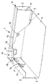
Die Erfindung ist nachstehend anhand der Zeichnung beispielsweise näher erläutert. Diese zeigt in perspektivischer Darstellung eine Innenansicht des Eckenbereiches eines Regalbodens gemäß der Erfindung von schräg unten gesehen, d.h. in gegenüber der Einbaustellung um 180° gedrehter Position.The invention is explained below with reference to the drawing, for example. This shows in perspective an interior view of the corner area of a shelf according to the invention viewed obliquely from below, i.e. in the position rotated by 180 ° in relation to the installation position.
Ein insgesamt mit 1 bezeichneter, einteilig aus einem zunächst ebenen Blechstück geformter Regalboden ist in seinem vorderen Randbereich zu einem kastenförmigen Längskantenprofil 2 umgebogen, wobei ein Endflansch 3 mit der Tragfläche 4 des Regalbodens durch Druckfügetechnik 5 verbunden ist. Der außenliegende Schenkel 6 des kastenförmigen Längskantenprofils 2 ist mit einem um 90° umgebogenen Eckenbereich 7 versehen, der dem Vertikalschenkel 8 des winkelförmigen Querkantenprofils 9 anliegt und mittels Druckfügetechnik 10 mit diesem verbunden ist.A shelf designated overall by 1 and formed in one piece from an initially flat piece of sheet metal is bent in its front edge region to form a box-shaped
Der innenliegende Schenkel 11 des kastenförmigen Längskantenprofils 2 ist im Eckenbereich ausgeschnitten (A) und mit einem Verbindungssteg 12 in die Ebene eines Endflansches 13 des Querkantenprofils 9, diesen unterdeckend, gebogen und mit diesem mittels Druckfügetechnik 14 verbunden, wobei im Eckenbereich der sich überdeckenden Teile eine Ausnehmung 15 zum leichten Einsetzen in einen nicht dargestellten, entweder am äußeren Schenkel 6 oder Vertikalschenkel 8 des Längs- oder Querkantenprofils 2 bzw. 9 angreifenden Regalbodenträgers ausgebildet ist, derart, daß sich der Verbindungssteg 12 diagonal zwischen dem Endflansch 13 und dem in gleicher Ebene befindlichen Steg 15 des kastenförmigen Längskantenprofils 2 erstreckt.The
Außerdem ist der innenliegende Schenkel 11 des kastenförmigen Längskantenprofils 2 angrenzend an den Verbindungssteg 14 ein Stück ausgeschnitten, derart, daß von innen ein Zugang zu Ausschnitten 16 im außenliegenden Schenkel 6 des kastenförmigen Längskantenprofils 2 möglich ist, um beispielsweise Verschraubungsarbeiten an durch die Ausnehmungen 16 gesteckten Befestigungsschrauben vornehmen zu können.In addition, the
Wie erkennbar ist, kann aufgrund der beschriebenen Ausbildung ein Regalboden der betreffenden Art in um 180° gedrehter Stellung von oben in nicht gezeigte Regalbodenträger eines ebenfalls nicht gezeigten Regalpfostens eingehängt werden, und zwar wahlweise sowohl mit dem außenliegenden Schenkel 6 des Längskantenprofils 2 als auch des Vertikalschenkels 8 des Querkantenprofils 9, ohne die Ecksteifigkeit des Regalbodens wesentlich zu beeinträchtigen.As can be seen, due to the design described, a shelf of the type in question can be hung in a position rotated by 180 ° from above into shelf supports, not shown, of a shelf post, also not shown are, either with the
Claims (4)
- A shelf member (1) with stiffening profiles formed by folded-over portions at the longitudinal and transverse edges (2, 9), wherein at least the stiffening profile at the front longitudinal edge is formed as a closed quadrangle, in particular a rectangular tubular cross-section, and has an end flange (13) which lies on the underside of the shelf member (1) and which is provided outside the tubular cross-section while the stiffening profiles of both transverse edges are of an angular cross-section, characterised in that in the corner region between longitudinal and transverse edge profiles (2, 9) the inward limb (11) of the box-shaped longitudinal edge profile (2) is cut away and bent into the plane of the end flange (13) of the transverse edge profile (9), extending under or over same, and is connected to same, wherein an opening (A) is provided in the corner region of the overlapping portions (12, 13) to receive a shelf member carrier engaging either the longitudinal or the transverse edge profile (2, 9).
- A shelf member according to claim 1 characterised in that the connection between the two overlapping portions (12, 13) is formed by means of a pressure joining process or material deformation (14) of the respective portions.
- A shelf member according to claim 1 or claim 2 characterised in that the vertical limb (6) of the longitudinal or transverse stiffening profile (2) is bent over through 90° in the corner region and bears from the inside against the vertical limb (8) of the other stiffening profile (9).
- A shelf member according to claim 1 or one of the following claims characterised in that the region adjoining the cut-out and bent-over connecting portion (12) of the inward limb (11) of the box-shaped longitudinal edge profile (2) is cut out in respect of a portion thereof.
Priority Applications (1)
| Application Number | Priority Date | Filing Date | Title |
|---|---|---|---|
| AT91111078T ATE102453T1 (en) | 1990-10-02 | 1991-07-04 | SHELVES WITH REINFORCEMENT PROFILES FORMED BY BENDS. |
Applications Claiming Priority (2)
| Application Number | Priority Date | Filing Date | Title |
|---|---|---|---|
| DE9013711U DE9013711U1 (en) | 1990-10-02 | 1990-10-02 | |
| DE9013711U | 1990-10-02 |
Publications (2)
| Publication Number | Publication Date |
|---|---|
| EP0478902A1 EP0478902A1 (en) | 1992-04-08 |
| EP0478902B1 true EP0478902B1 (en) | 1994-03-09 |
Family
ID=6857985
Family Applications (1)
| Application Number | Title | Priority Date | Filing Date |
|---|---|---|---|
| EP91111078A Expired - Lifetime EP0478902B1 (en) | 1990-10-02 | 1991-07-04 | Shelf with folded reinforcement members |
Country Status (4)
| Country | Link |
|---|---|
| EP (1) | EP0478902B1 (en) |
| AT (1) | ATE102453T1 (en) |
| DE (2) | DE9013711U1 (en) |
| ES (1) | ES2050486T3 (en) |
Families Citing this family (4)
| Publication number | Priority date | Publication date | Assignee | Title |
|---|---|---|---|---|
| DE4211001C1 (en) * | 1992-04-02 | 1992-12-17 | Bito-Lagertechnik Bittmann Gmbh, 6554 Meisenheim, De | Shelf bottom with flat deposition surface - has stiffening profile, whose inner, vertical, side wall is orthogonal to inner strap in corner region |
| DE20112323U1 (en) * | 2001-07-26 | 2001-09-27 | Meta Regalbau Gmbh & Co Kg | Shelf for a shelf and shelf |
| BE1014845A5 (en) * | 2002-05-27 | 2004-05-04 | Avasco Industries Bv | Shelf for a rack system and method for |
| DE202008008920U1 (en) * | 2008-07-03 | 2009-11-26 | Meta-Regalbau Gmbh & Co. Kg | Sheet metal processing for a shelf and shelf from this sheet metal processing |
Family Cites Families (4)
| Publication number | Priority date | Publication date | Assignee | Title |
|---|---|---|---|---|
| US1984080A (en) * | 1932-07-29 | 1934-12-11 | Luxe Metal Furniture Company D | Shelving |
| US4269318A (en) * | 1979-09-07 | 1981-05-26 | Ben Levitt | Sheet metal shelf |
| DE8018148U1 (en) * | 1980-07-05 | 1980-10-09 | Fritz Schaefer Gmbh Fabriken Fuer Lager- Und Betriebseinrichtungen, Salchendorf Bei Neunkirchen, Kreis Siegen, 5908 Neunkirchen | SHELF FLOOR WITH REINFORCING PROFILES MADE BY BENDING |
| AT382505B (en) * | 1982-12-06 | 1987-03-10 | Voest Alpine Krems | SHELF FROM SHEET |
-
1990
- 1990-10-02 DE DE9013711U patent/DE9013711U1/de not_active Expired - Lifetime
-
1991
- 1991-07-04 ES ES91111078T patent/ES2050486T3/en not_active Expired - Lifetime
- 1991-07-04 DE DE91111078T patent/DE59101155D1/en not_active Expired - Lifetime
- 1991-07-04 EP EP91111078A patent/EP0478902B1/en not_active Expired - Lifetime
- 1991-07-04 AT AT91111078T patent/ATE102453T1/en not_active IP Right Cessation
Also Published As
| Publication number | Publication date |
|---|---|
| DE59101155D1 (en) | 1994-04-14 |
| ES2050486T3 (en) | 1994-05-16 |
| ATE102453T1 (en) | 1994-03-15 |
| EP0478902A1 (en) | 1992-04-08 |
| DE9013711U1 (en) | 1990-12-06 |
Similar Documents
| Publication | Publication Date | Title |
|---|---|---|
| DE19750427C1 (en) | Fastening device | |
| EP0853832B1 (en) | Framework for switchgear cabinets | |
| EP0308715B1 (en) | Electrical cabinet | |
| EP0176002B1 (en) | Rack | |
| DE2808484C2 (en) | ||
| DE2446804A1 (en) | DRAWER | |
| EP0735209A1 (en) | Cross or longitudinal supporting section for a ceiling covering | |
| DE3615354C1 (en) | Arrangement for locking a container | |
| EP0478902B1 (en) | Shelf with folded reinforcement members | |
| DE8017644U1 (en) | CORNER ANGLE FOR CONNECTING TWO SPACER HOLE PROFILES OF AN INSULATED GLASS DISC | |
| DE7027532U (en) | SHELF. | |
| AT401854B (en) | DRAWER | |
| CH651457A5 (en) | SHELF FLOOR WITH REINFORCING PROFILES MADE BY BENDING. | |
| EP0010291B1 (en) | Switch cabinet | |
| EP0493371A1 (en) | Container, in particular silo | |
| DE3247506A1 (en) | Gas-tight counter-ceiling | |
| WO1992011171A1 (en) | Holder on vehicle bodywork, especially as a suspension seating | |
| EP0465904B1 (en) | Ceiling cladding | |
| EP0465905A1 (en) | Ceiling cladding | |
| DE10143918B4 (en) | switch cabinet | |
| DE2448689B2 (en) | HINGE ARM IN SHEET METAL | |
| DE2916017C2 (en) | Frame for a hanging file | |
| CH657584A5 (en) | Corner connection element | |
| EP0007480B1 (en) | Set of parts for the construction of shelvings | |
| DE4021773A1 (en) | CONTROL CABINET WITH A SCREEN COVERED BY WALL ELEMENTS AND DOOR |
Legal Events
| Date | Code | Title | Description |
|---|---|---|---|
| PUAI | Public reference made under article 153(3) epc to a published international application that has entered the european phase |
Free format text: ORIGINAL CODE: 0009012 |
|
| 17P | Request for examination filed |
Effective date: 19920129 |
|
| AK | Designated contracting states |
Kind code of ref document: A1 Designated state(s): AT BE CH DE ES FR GB GR IT LI LU NL SE |
|
| 17Q | First examination report despatched |
Effective date: 19930727 |
|
| GRAA | (expected) grant |
Free format text: ORIGINAL CODE: 0009210 |
|
| AK | Designated contracting states |
Kind code of ref document: B1 Designated state(s): AT BE CH DE ES FR GB GR IT LI LU NL SE |
|
| REF | Corresponds to: |
Ref document number: 102453 Country of ref document: AT Date of ref document: 19940315 Kind code of ref document: T |
|
| REF | Corresponds to: |
Ref document number: 59101155 Country of ref document: DE Date of ref document: 19940414 |
|
| REG | Reference to a national code |
Ref country code: ES Ref legal event code: FG2A Ref document number: 2050486 Country of ref document: ES Kind code of ref document: T3 |
|
| GBT | Gb: translation of ep patent filed (gb section 77(6)(a)/1977) |
Effective date: 19940503 |
|
| ITF | It: translation for a ep patent filed |
Owner name: MODIANO & ASSOCIATI S.R.L. |
|
| ET | Fr: translation filed | ||
| EPTA | Lu: last paid annual fee | ||
| REG | Reference to a national code |
Ref country code: GR Ref legal event code: FG4A Free format text: 3012109 |
|
| PLBE | No opposition filed within time limit |
Free format text: ORIGINAL CODE: 0009261 |
|
| STAA | Information on the status of an ep patent application or granted ep patent |
Free format text: STATUS: NO OPPOSITION FILED WITHIN TIME LIMIT |
|
| EAL | Se: european patent in force in sweden |
Ref document number: 91111078.1 |
|
| 26N | No opposition filed | ||
| PGFP | Annual fee paid to national office [announced via postgrant information from national office to epo] |
Ref country code: GR Payment date: 19950419 Year of fee payment: 5 |
|
| PGFP | Annual fee paid to national office [announced via postgrant information from national office to epo] |
Ref country code: ES Payment date: 19950525 Year of fee payment: 5 |
|
| PGFP | Annual fee paid to national office [announced via postgrant information from national office to epo] |
Ref country code: FR Payment date: 19950530 Year of fee payment: 5 |
|
| PGFP | Annual fee paid to national office [announced via postgrant information from national office to epo] |
Ref country code: AT Payment date: 19950727 Year of fee payment: 5 |
|
| PG25 | Lapsed in a contracting state [announced via postgrant information from national office to epo] |
Ref country code: AT Effective date: 19960704 |
|
| PG25 | Lapsed in a contracting state [announced via postgrant information from national office to epo] |
Ref country code: ES Free format text: LAPSE BECAUSE OF EXPIRATION OF PROTECTION Effective date: 19960705 |
|
| PG25 | Lapsed in a contracting state [announced via postgrant information from national office to epo] |
Ref country code: GR Free format text: THE PATENT HAS BEEN ANNULLED BY A DECISION OF A NATIONAL AUTHORITY Effective date: 19970131 |
|
| REG | Reference to a national code |
Ref country code: GR Ref legal event code: MM2A Free format text: 3012109 |
|
| PG25 | Lapsed in a contracting state [announced via postgrant information from national office to epo] |
Ref country code: FR Effective date: 19970328 |
|
| REG | Reference to a national code |
Ref country code: FR Ref legal event code: ST |
|
| REG | Reference to a national code |
Ref country code: ES Ref legal event code: FD2A Effective date: 19990601 |
|
| REG | Reference to a national code |
Ref country code: GB Ref legal event code: IF02 |
|
| PGFP | Annual fee paid to national office [announced via postgrant information from national office to epo] |
Ref country code: GB Payment date: 20030715 Year of fee payment: 13 |
|
| PGFP | Annual fee paid to national office [announced via postgrant information from national office to epo] |
Ref country code: NL Payment date: 20030721 Year of fee payment: 13 |
|
| PGFP | Annual fee paid to national office [announced via postgrant information from national office to epo] |
Ref country code: CH Payment date: 20030728 Year of fee payment: 13 Ref country code: LU Payment date: 20030728 Year of fee payment: 13 Ref country code: SE Payment date: 20030728 Year of fee payment: 13 |
|
| PGFP | Annual fee paid to national office [announced via postgrant information from national office to epo] |
Ref country code: BE Payment date: 20030729 Year of fee payment: 13 |
|
| PG25 | Lapsed in a contracting state [announced via postgrant information from national office to epo] |
Ref country code: GB Free format text: LAPSE BECAUSE OF NON-PAYMENT OF DUE FEES Effective date: 20040704 Ref country code: LU Free format text: LAPSE BECAUSE OF NON-PAYMENT OF DUE FEES Effective date: 20040704 |
|
| PG25 | Lapsed in a contracting state [announced via postgrant information from national office to epo] |
Ref country code: SE Free format text: LAPSE BECAUSE OF NON-PAYMENT OF DUE FEES Effective date: 20040705 |
|
| PG25 | Lapsed in a contracting state [announced via postgrant information from national office to epo] |
Ref country code: CH Free format text: LAPSE BECAUSE OF NON-PAYMENT OF DUE FEES Effective date: 20040731 Ref country code: LI Free format text: LAPSE BECAUSE OF NON-PAYMENT OF DUE FEES Effective date: 20040731 Ref country code: BE Free format text: LAPSE BECAUSE OF NON-PAYMENT OF DUE FEES Effective date: 20040731 |
|
| BERE | Be: lapsed |
Owner name: *MAUSER WALDECK A.G. Effective date: 20040731 |
|
| PG25 | Lapsed in a contracting state [announced via postgrant information from national office to epo] |
Ref country code: NL Free format text: LAPSE BECAUSE OF NON-PAYMENT OF DUE FEES Effective date: 20050201 |
|
| GBPC | Gb: european patent ceased through non-payment of renewal fee |
Effective date: 20040704 |
|
| EUG | Se: european patent has lapsed | ||
| REG | Reference to a national code |
Ref country code: CH Ref legal event code: PL |
|
| NLV4 | Nl: lapsed or anulled due to non-payment of the annual fee |
Effective date: 20050201 |
|
| PG25 | Lapsed in a contracting state [announced via postgrant information from national office to epo] |
Ref country code: IT Free format text: LAPSE BECAUSE OF NON-PAYMENT OF DUE FEES;WARNING: LAPSES OF ITALIAN PATENTS WITH EFFECTIVE DATE BEFORE 2007 MAY HAVE OCCURRED AT ANY TIME BEFORE 2007. THE CORRECT EFFECTIVE DATE MAY BE DIFFERENT FROM THE ONE RECORDED. Effective date: 20050704 |
|
| BERE | Be: lapsed |
Owner name: *MAUSER WALDECK A.G. Effective date: 20040731 |
|
| PGFP | Annual fee paid to national office [announced via postgrant information from national office to epo] |
Ref country code: DE Payment date: 20100826 Year of fee payment: 20 |
|
| REG | Reference to a national code |
Ref country code: DE Ref legal event code: R071 Ref document number: 59101155 Country of ref document: DE |
|
| REG | Reference to a national code |
Ref country code: DE Ref legal event code: R071 Ref document number: 59101155 Country of ref document: DE |
|
| PG25 | Lapsed in a contracting state [announced via postgrant information from national office to epo] |
Ref country code: DE Free format text: LAPSE BECAUSE OF EXPIRATION OF PROTECTION Effective date: 20110705 |