EP0010291B1 - Switch cabinet - Google Patents
Switch cabinet Download PDFInfo
- Publication number
- EP0010291B1 EP0010291B1 EP79103991A EP79103991A EP0010291B1 EP 0010291 B1 EP0010291 B1 EP 0010291B1 EP 79103991 A EP79103991 A EP 79103991A EP 79103991 A EP79103991 A EP 79103991A EP 0010291 B1 EP0010291 B1 EP 0010291B1
- Authority
- EP
- European Patent Office
- Prior art keywords
- frame
- mounting flanges
- switch cabinet
- wall
- flanges
- Prior art date
- Legal status (The legal status is an assumption and is not a legal conclusion. Google has not performed a legal analysis and makes no representation as to the accuracy of the status listed.)
- Expired
Links
Images


Classifications
-
- H—ELECTRICITY
- H02—GENERATION; CONVERSION OR DISTRIBUTION OF ELECTRIC POWER
- H02B—BOARDS, SUBSTATIONS OR SWITCHING ARRANGEMENTS FOR THE SUPPLY OR DISTRIBUTION OF ELECTRIC POWER
- H02B1/00—Frameworks, boards, panels, desks, casings; Details of substations or switching arrangements
- H02B1/26—Casings; Parts thereof or accessories therefor
- H02B1/30—Cabinet-type casings; Parts thereof or accessories therefor
Definitions
- the invention relates to a control cabinet for receiving built-in parts, such as switching and / or control elements, with a separately produced frame-like, profiled frame, which forms the side walls, the top wall and the bottom wall of the control cabinet and which has angled fastening flanges on the frame edges to which the rear wall and the door or the front wall are attached.
- Control cabinets should have as many attachment points as possible so that there is extensive freedom for the installation of built-in parts.
- the attachment points should be such that they are firmly connected to the cabinet body in order to ensure secure mounting of built-in parts.
- a control cabinet with a closed frame is known from FR-A 1 575 650.
- the mounting flanges are only attached to a part of the frame edges and are usually only used to attach joints for a door and as a contact surface for this door.
- fastening flanges are set back relative to their facing frame edges, that the fastening flanges of the front frame edges are parallel and the fastening flanges of the rear frame edges run at right angles to the respectively facing frame walls and that the fastening flanges each have U-shaped curved sections pass into the associated frame walls, forming a groove for sealing elements which is open towards the outside of the frame.
- the sealing elements can be used without additional fastening means, which ensure that the housing assembled in this way is clearly sealed when the rear wall, door or front wall is attached.
- the mounting flanges aligned in this way also offer the possibility that other installation parts can also be attached to them
- mounting flanges are provided with rows of holes. It is advantageous if the design is such that the holes are arranged on fastening flanges lying parallel to one another in horizontal or vertical planes.
- the bending of the frame hinge to the closed frame is facilitated in that the fastening flanges are provided with sections in the corner regions of the frame.
- the frame is closed with a rear wall according to an embodiment in such a way that a rear wall or a mounting plate is attached to the fastening flanges of the rear frame edges and is connected to them.
- the end of the frame on the front provides, according to a further embodiment, that fastening brackets are attached to the fastening flanges of the front frame edges and that a door or a front wall is connected to the legs of the fastening flanges perpendicular to the fastening flanges.
- the one-piece attachment of the fastening flanges to the frame is made possible in that the frame edges merge into the U-shaped sections of the fastening flanges via i80 'bends and that the fastening flanges of the front frame edges running parallel to the associated frame walls have 180' bends in theirs go over assigned U-shaped curved sections.
- fastening flanges are divided into the corner regions of the frame and that after the frame has been bent, the overlapping regions of the divided fastening flanges are firmly connected to one another, then the stability of the frame is improved by the closed circumferential fastening flanges.
- the cabinet essentially consists (see FIG. 2) of a frame 1, a rear wall 2 and a door 3.
- a mounting plate 4 can also be fitted inside the cabinet, two mounting options for the mounting plate being shown in FIG.
- the profile of frame 1 should be considered.
- the frame 1 forms a fastening flange 5 on the front of the cabinet.
- the fastening flange 5 extends parallel to the respective frame wall. It changes over a 180 'bend 6 into a section 7 which forms the wall of a groove 8 for a sealing element 35.
- the section 7 merges into a section 9, which forms the bottom of the groove 8.
- Section 9 merges into a section 10, which runs parallel to section 7, via a 90 ° bend.
- the section 10 merges via a 180 ° bend 11 into a section 12 which runs parallel to the section 10, the sections 10 and 12 abutting one another without a gap.
- Section 12 continues over the entire width of the frame 1. However, there is an opening 13 on the lower frame wall 12a, which forms the bottom wall, which can be locked with a cover 37.
- the opening 13 is located in a recess in the frame wall 12a.
- the frame walls 12b, 12c of the frame 1 form the side walls and the frame wall 12d forms the top wall of the frame 1.
- the section 12 merges via a 180 ° bend 14 into a section 15 which bears against the frame wall, so that there is the same duplication as on the front of the frame 1.
- the section 15 merges a 90 ° bend in a section 16, which forms the bottom of a groove 17 for the sealing element 36.
- the section 16 merges via a right-angled bend into a section 18, which merges into the fastening flange 19 via a further 90 ° bend, which extends at right angles to the frame walls 12a to 12d.
- the frame 1 is produced by first rolling a band with the profile described. The tape is then divided into pieces and holes 21 and 26 are punched into the mounting flanges 5 and 19, the arrangement of which will be described. In addition, incisions or notches must be provided in the later corners. The corner configurations will be described below with reference to FIGS. 4 and 5.
- Fig. 4 shows a rear frame corner.
- a relief 20 was installed before the frame corner was made. This notch 20 extends approximately over half the depth of section 16. Beyond the hole 21 located in the corner region, the fastening flanges 19 adjoining one another at right angles overlap and are connected to one another by spot welding. In the area 22 between the end of the notch 20 and the frame corner, the material can be deformed to such an extent that the frame 1 can be bent. At the overlap point 23 of the mounting flanges 19, these are connected to one another by spot welding.
- a notch was also attached before it bent, which also only extends over approximately half of the section 7.
- the mounting flanges 5 are, however, cut out widely, as the cutouts 24 and 25 show, since an overlap is out of the question because of the different orientation of the mounting flanges 5.
- the mounting flanges 5 and 19 each extend over the circumference of the frame 1.
- Each mounting flange has a row of holes, the holes 21 of the rear mounting flanges 19 and the holes 26 of the front mounting flanges 5 being arranged at the same height, i. H. in a horizontal sectional plane that passes through a hole 21, holes of the other three vertical fastening flanges 5 and 19 are also detected.
- This cutting plane also detects holes in the three other mounting flanges.
- the pitch of the holes 21 and 26 is preferably constant over the entire length of the mounting flanges 5 and 19.
- the frame band is cut out, cut off and bent in such a way that the ends meet in the middle of the lower frame wall 12a, that is to say in the area of the opening 13.
- There the ends of the frame 1 are joined together by butt welding.
- the welding in the area of the opening 13 has the advantage that the length of the weld seam compared to other areas of the frame 1 is substantially shortened by the width of the opening 13.
- the door 3 has a large flat surface 3a, which at its edges merges into rectangular bevels 3b which are present on all sides of the rectangular surface 3a. At the corners there are welds not shown in the drawing.
- the door 3 is fastened to the frame 1 by means of hinges, identified overall by 27 and 28.
- the hinges (see FIG. 3) have fastening tabs 29 which bear against a vertical fastening flange 5 and are connected to the fastening flange by brackets 30 which are located both in the fastening tabs 29 and in a hole 26 of the mounting flange 5 engage.
- brackets 33 are fastened to the fastening flanges 5, which have a front leg 33a, which is oriented at right angles to the frame walls 12b and 12c and to which a front wall can be fastened.
- a mounting plate 4 can also be provided, which can either (see FIG. 2) be screwed directly onto the rear mounting flange 19 or which (alternative, which is shown in FIG. 2 above) is offset to the rear relative to the mounting flange . In this further type of attachment, the mounting plate 4 is connected to the rear wall 2 and can be removed together with this.
- the rear wall 2 has a large rear wall surface 2a, the edges of which merge into rectangular bevels 2b.
- an alternative embodiment for a rear wall is shown in dashed lines, which is denoted by 2 '.
- the edge folds 2b ' have a particularly large height, so that the rear wall 2' projects beyond the frame 1 to the rear. In this way, protruding surfaces are formed, into which cable bushings 34 (see FIG. 3) can be introduced.
- sealing elements 35 and 36 with which the control cabinet is closed in a dustproof and splashproof manner.
- These are soft-elastic sealing elements which are inserted into the grooves 8 and 17 and against which the edges of the door 3 and the rear wall 2 rest. Since the base of the groove is not carved to the corner in the corner areas (see in particular FIG. 4, end of the notch 20), a very good seal is obtained; there is no open slot.
- the front fastening flanges 5 are at a certain distance a from the respective parallel frame wall 12a to 12d, so that the fastening flanges 5 can be gripped behind for the purpose of fastening internals.
Landscapes
- Engineering & Computer Science (AREA)
- Power Engineering (AREA)
- Patch Boards (AREA)
- Casings For Electric Apparatus (AREA)
- Switch Cases, Indication, And Locking (AREA)
Abstract
Description
Die Erfindung betrifft einen Schaltschrank für die Aufnahme von Einbauteilen, wie Schalt-und/oder Steuerungselementen, mit einer separat hergestellten rahmenartigen, profilierten Zarge, welche die Seitenwände, die Deckwand und die Bodenwand des Schaltschrankes bildet und die an den Zargenrändern abgewinkelte Befestigungsflansche aufweist, an denen die Rückwand und die Tür oder die Vorderwand angebracht sind.The invention relates to a control cabinet for receiving built-in parts, such as switching and / or control elements, with a separately produced frame-like, profiled frame, which forms the side walls, the top wall and the bottom wall of the control cabinet and which has angled fastening flanges on the frame edges to which the rear wall and the door or the front wall are attached.
Schaltschränke sollen möglichst viele Befestigungsstellen aufweisen, damit für die Anbringung von Einbauteilen weitgehende Freiheit besteht Die Befestigungsstellen sollen so beschaffen sein, daß sie mit dem Schrankkörper fest verbunden sind, um eine sichere Halterung von Einbauteilen zu gewährleisten. Diese Forderungen werden zum Teil von gelochten Montageplatten erfüllt, jedoch besteht das Bedürfnis, zusätzliche Befestigungssteller zur Verfügung zu haben, damit auch außerhalb einer Montageplatte Befestigungen möglich sind bzw. spezielle Montageplatten überhaupt vermieden werden können. Obwohl an Schaltschränke relativ hohe Anforderungen hinsichtlich Stabilität und Dichtheit gestellt werden, sollen sie möglichst billig hergestellt werden können.Control cabinets should have as many attachment points as possible so that there is extensive freedom for the installation of built-in parts. The attachment points should be such that they are firmly connected to the cabinet body in order to ensure secure mounting of built-in parts. These requirements are met in part by perforated mounting plates, but there is a need to have additional fastening plates available so that fastenings are also possible outside a mounting plate or special mounting plates can be avoided at all. Although relatively high demands are placed on control cabinets in terms of stability and tightness, it should be possible to manufacture them as cheaply as possible.
Ein Schaltschrank mit einer geschlossenen Zarge ist durch die FR-A 1 575 650 bekannt. Dabei sind die Befestigungsflansche nur an einem Teil der Zargenränder angebracht und dienen in der Regel nur zur Anbringung von Gelenken für eine Tür, sowie als Anlagefläche für diese Tür.A control cabinet with a closed frame is known from FR-A 1 575 650. The mounting flanges are only attached to a part of the frame edges and are usually only used to attach joints for a door and as a contact surface for this door.
Ein derartiger Schaltschrank erfüllt aber nicht die eingangs gestellten Forderungen, da er insbesondere durch eine Rückwand und eine Tür oder eine Vorderwand nicht dicht abgeschlossen werden kann.However, such a control cabinet does not meet the requirements stated at the outset, since it cannot be sealed off in particular by a rear wall and a door or a front wall.
Es ist Aufgabe der vorliegenden Erfindung, einen Schaltschrank der eingangs erwähnten Art zu schaffen, der durch die Verwendung eines profilierten Ausgangsmaterials für die Zarge in der Herstellung vereinfacht werden kann und bei dem durch besondere Ausgestaltung der Zargenränder mit den Befestigungsflanschen die Rückwand und die Tür oder die Vorderwand absolut dicht mit der Zarge verbunden werden können.It is an object of the present invention to provide a control cabinet of the type mentioned at the outset, which can be simplified in the manufacture by using a profiled starting material for the frame and in which the rear wall and the door or the through special design of the frame edges with the fastening flanges Front wall can be absolutely tightly connected to the frame.
Diese Aufgabe wird nach der Erfindung dadurch gelöst, daß die Befestigungsflansche gegenüber ihren zugekehrten Zargenrändern zurückgesetzt sind, daß die Befestigungsfiansche der vorderen Zargenränder parallel und die Befestigungsflansche der hinteren Zargenränder rechtwinklig zu den jeweils zugekehrten Zargenwänden verlaufen und daß die Befestigungsflansehe jeweils über U-förmig gebogene Abschnitte unter Bildung einer jeweils zur Außenseite der Zarge hin offenen Nut für Dichtungselemente in die zugeordneten Zargenwände übergehen.This object is achieved according to the invention in that the fastening flanges are set back relative to their facing frame edges, that the fastening flanges of the front frame edges are parallel and the fastening flanges of the rear frame edges run at right angles to the respectively facing frame walls and that the fastening flanges each have U-shaped curved sections pass into the associated frame walls, forming a groove for sealing elements which is open towards the outside of the frame.
Durch diese Ausgestaltung der Zargenränder und Befestigungsflansche können ohne zusätzliche Befestigungsmittel die Dichtungselemente eingesetzt werden, die bei der Anbringung der Rückwand, der Tür oder der Vorderwand für die eindeutige Abdichtung des so zusammengesetzten Gehäuses sorgen. Darüber hinaus bieten die so ausgerichteten Befestigungsflansche zusätzlich die Möglichkeit, daß daran auch andere Einbauteile befestigt werden könnenWith this design of the frame edges and fastening flanges, the sealing elements can be used without additional fastening means, which ensure that the housing assembled in this way is clearly sealed when the rear wall, door or front wall is attached. In addition, the mounting flanges aligned in this way also offer the possibility that other installation parts can also be attached to them
Die Anbringung von zusätzlichen Einbauteilen an den Befestigungsflanschen wird nach einer Ausgestaltung dadurch erleichtert, daß die Befestigungsflansche mit Reihen von Löchern versehen sind. Dabei ist es von Vorteil, wenn die Auslegung so ist, daß die Löcher an zueinander parallel liegenden Befestigungsflanschen in horizontaler oder vertikalen Ebenen angeordnet sind.The attachment of additional built-in parts on the mounting flanges is facilitated in one embodiment in that the mounting flanges are provided with rows of holes. It is advantageous if the design is such that the holes are arranged on fastening flanges lying parallel to one another in horizontal or vertical planes.
Das Biegen des Zargenbandes zur geschlossenen Zarge wird dadurch erleichtert, daß die Befestigungsflansche in den Eckbereichen der Zarge mit Abschnitten versehen sind. Der Abschluß der Zarge mit einer Rückwand erfolgt nach einer Ausgestaltung derart, daß an den Befestigungsflanschen der hinteren Zargenränder eine Rückwand oder eine Montageplatte angelegt und mit diesen verbunden ist.The bending of the frame hinge to the closed frame is facilitated in that the fastening flanges are provided with sections in the corner regions of the frame. The frame is closed with a rear wall according to an embodiment in such a way that a rear wall or a mounting plate is attached to the fastening flanges of the rear frame edges and is connected to them.
Der Abschluß der Zarge auf der Vorderseite sieht nach einer weiteren Ausgestaltung vor, daß an den Befestigungsflanschen der vorderen Zargenränder Befestigungswinkel angebracht sind und daß mit den senkrecht zu den Befestigungsflanschen stehenden Schenkeln der Befestigungswinkel eine Tür oder eine Vorderwand verbunden ist.The end of the frame on the front provides, according to a further embodiment, that fastening brackets are attached to the fastening flanges of the front frame edges and that a door or a front wall is connected to the legs of the fastening flanges perpendicular to the fastening flanges.
Die einstückige Anbringung der Befestigungsflansche an der Zarge wird dadurch ermöglicht, daß die Zargenränder über i80'-Abbiegungen in die U-förmig gebogenen Abschnitte der Befestigungsflansche übergehen und daß die parallel zu den zugeordneten Zargenwänden verlaufenden Befestigungsflansche der vorderen Zargenränder über 180'-Abbiegungen in ihre zugeordnete U-förmig gebogenen Abschnitte übergehen.The one-piece attachment of the fastening flanges to the frame is made possible in that the frame edges merge into the U-shaped sections of the fastening flanges via i80 'bends and that the fastening flanges of the front frame edges running parallel to the associated frame walls have 180' bends in theirs go over assigned U-shaped curved sections.
Ist nach einer Weiterbildung vorgesehen, daß die Befestigungsflansche in den Eckbereichen der Zarge unterteilt sind und daß nach dem Biegen der Zarge die sich überlappenden Bereiche der unterteilten Befestigungsflansche fest miteinander verbunden sind, dann wird durch die geschlossenen umlaufenden Befestigungsflansche die Stabilität der Zarge verbessert.If it is provided according to a further development that the fastening flanges are divided into the corner regions of the frame and that after the frame has been bent, the overlapping regions of the divided fastening flanges are firmly connected to one another, then the stability of the frame is improved by the closed circumferential fastening flanges.
In den Zeichnungen ist ein Ausführungsbeispiel der Erfindung dargestellt. Es zeigt
- Fig. 1 eine Vorderansicht eines Schaltschrankes gemäß der Erfindung,
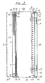
- Fig. 2 einen senkrechten Schnitt nach Linie 2-2 in Fig. 1,
- Fig. 3 einen horizontalen Schnitt nach Linie 3-3 in Fig. 1,
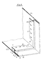
- Fig.4 eine perspektivische Darstellung der Ausbildung einer hinteren Zargendecke und
- Fig. 5 eine perspektivische Darstellung der Ausbildung einer vorderen Zargenecke.
- 1 is a front view of a cabinet according to the invention,
- 2 is a vertical section along line 2-2 in Fig. 1,
- 3 is a horizontal section along line 3-3 in Fig. 1,
- 4 shows a perspective view of the formation of a rear frame ceiling and
- Fig. 5 is a perspective view of the formation of a front frame corner.
Der Schrank besteht im wesentlichen (s. Fig. 2) aus einer Zarge 1, einer Rückwand 2 und einer Tür 3. Innerhalb des Schrankes kann auch eine Montageplatte 4 angebracht sein, wobei in Fig. 2 zwei Anbringungsmöglichkeiten für die Montageplatte gezeigt sind.The cabinet essentially consists (see FIG. 2) of a
Zunächst soll das Pofil der Zarge 1 betrachtet werden. Bei dem dargestellten Ausführungsbeispiel sei angenommen, daß es sich um eine aus Stahlblech geformte Zarge handelt. Die Zarge 1 bildet an der Schrankvorderseite einen Befestigungsflansch 5. Der Befestigungsflansch 5 erstreckt sich parallel zu der jeweiligen Zargenwand. Er geht über eine 180'-Abbiegung 6 in einen Abschnitt 7 über, der die Wand einer Nut 8 für ein Dichtungselement 35 bildet. Der Abschnitt 7 geht in einen Abschnitt 9 über, der den Grund der Nut 8 bildet. Der Abschnitt 9 geht über eine 90°-Abbiegung in einen Abschnitt 10 über, der parallel zum Abschnitt 7 verläuft. Der Abschnitt 10 geht über eine 180°-Abbiegung 11 in einen Abschnitt 12 über, der parallel zum Abschnitt 10 verläuft, wobei die Abschnitte 10 und 12 ohne Zwischenraum aneinanderliegen..First, the profile of
Der Abschnitt 12 setzt sich über die gesamte Breite der Zarge 1 fort. Allerdings ist an der unteren Zargenwand 12a, die die Bodenwand bildet, ein Durchbruch 13 vorhanden, der mit einem Deckel 37 abschließbar ist. Der Durchbruch 13 befindet sich in einer Vertiefung der Zargenwand 12a. Die Zargenwände 12b, 12c der Zarge 1 bilden die Seitenwände und die Zargenwand 12d bildet die Deckwand der Zarge 1.
An der Rückseite der Zarge 1 geht der Abschnitt 12 über eine 180°-Abbiegung 14 in einen Abschnitt 15 über, der an der Zargenwand anliegt, so daß dort eine gleiche Doppelung vorhanden ist wie an der Vorderseite der Zarge 1. Der Abschnitt 15 geht über eine 90°-Abbiegung in einen Abschnitt 16 über, der den Grund einer Nut 17 für das Dichtungselement 36 bildet. Der Abschnitt 16 geht über eine rechtwinklige Abbiegung in einen Abschnitt 18 über, der über eine weitere 90°-Abbiegung in den Befestigungsflansch 19 übergeht, der sich rechtwinklig zu den Zargenwänden 12a bis 12d erstreckt.At the rear of the
Die diversen Abschnitte sind auch in den vergrößerten Darstellungen nach den Fig. 4 und 5 bezeichnet und körben dort besser unterschieden werden.The various sections are also designated in the enlarged representations according to FIGS. 4 and 5, and baskets can be better distinguished there.
Die Zarge 1 wird dadurch hergestellt, daß zunächst ein Band mit dem beschriebenen Profil gewalzt wird. Das Band wird dann in Stücke unterteilt und in die Befestigungsflansche 5 und 19 werden Löcher 21 und 26 gestanzt, deren Anordnung noch beschrieben wird. Außerdem müssen in den späteren Ecken Einschnitte bzw. Ausklinkungen vorgesehen werden. Die Eckausbildungen sollen nachstehend anhand der Fig. 4. und 5 beschrieben werden.The
Fig. 4 zeigt eine hintere Zargenecke. Vor der Herstellung der Zargenecke wurde eine Ausldinkung 20 angebracht. Diese Ausklinkung 20 reicht etwa noch über die Hälfte der Tiefe des Abschnittes 16. Jenseits des im Eckbereich liegenden Loches 21 überlappen sich die rechtwinklig aneinander anschließenden Befestigungsflansche 19 und sind durch Punktschweißung miteinander verbunden. In dem Bereich 22 zwischen dem Ende der Ausklinkung 20 und der Zargenecke läßt sich das Material so weit verformen, daß ein Umbiegen der Zarge 1 möglich ist. An der Überlappungsstelle 23 der Befestigungsflansche 19 sind diese durch eine Punktschweißung miteinander verbunden.Fig. 4 shows a rear frame corner. Before the frame corner was made, a
Im Bereich der vorderen Ecken der Zarge 1 wurde vor deren Zusammenbiegung ebenfalls eine Ausklinkung angebracht, die sich auch nur etwa über die Hälfte des Abschnittes 7 erstreckt. Die Befestigungsflansche 5 sind jedoch weit ausgeschnitten, wie die Ausschnitte 24 und 25 zeigen, da ja eine Überlappung wegen der anderen Orientierung der Befestigungsflansche 5 nicht in Betracht kommt.In the area of the front corners of the
Die Befestigungsflansche 5 und 19 verlaufen jeweils über den Umfang der Zarge 1. Jeder Befestigungsflansch hat eine Lochreihe, wobei die Löcher 21 der hinteren Befestigungsflansche 19 und die Löcher 26 der vorderen Befestigungsflansche 5 in gleicher Höhe angeordnet sind, d. h. in einer horizontalen Schnittebene, die durch ein Loch 21 geht, werden auch Löcher der anderen drei senkrechten Be-festigungsflansche 5 und 19 erfaßt. Entsprechendes gilt für eine senkrechte Schnittebene, die durch ein Loch der horizontalen Befestigungsflansche 5 und 19 geht. Auch diese Schnittebene erfaßt Löcher der drei anderen Befestigungsflansche. Der Teilungsabstand der Löcher 21 und 26 ist vorzugsweise über die gesamte Länge der Befestigungsflansche 5 und 19 gleichbleibend.The
Das Zargenband wird so ausgeschnitten, abgeschnitten und gebogen, daß die Enden in der Mitte der unteren Zargenwand 12a, also im Bereich des Durchbruches 13, zusammenstoßen. Dort werden die Enden der Zarge 1 durch Stumpfschweißung miteinander verbunden. Die Verschweißung im Bereich des Durchbruches 13 hat den Vorteil, daß die Länge der Schweißnaht gegenüber anderen Bereichen der Zarge 1 im wesentlichen um die Breite des Durchbruches 13 verkürzt ist.The frame band is cut out, cut off and bent in such a way that the ends meet in the middle of the
Die Tür 3 hat eine große ebene Fläche 3a, die an ihren Rändern in rechtwinklige Abkantungen 3b übergeht, die an allen Seiten der rechteckigen Fläche 3a vorhanden sind. An den Ecken sind in der Zeichnung nicht dargestellte Verschwei- ßungen vorhanden. Die Tür 3 ist mittels insgesamt mit 27 und 28 bezeichneten Scharnieren an der Zarge 1 befestigt. Die Scharniere haben (s. Fig. 3) Befestigungslappen 29, die an einem senkrechten Befestigungsflansch 5 anliegen und mit dem Befestigungsflansch durch Klammern 30 verbunden sind, die sowohl in den Befestigungslappen 29 als auch in ein Loch 26 des Befestigungsflansches 5 eingreifen.The
An der Tür 3 befindet sich ein Schloß 31 mit einem Riegel 32, der im Schließzustand hinter die Kante eines vorderen Befestigungsflansches 5 greift.On the
Alternativ könnte man anstelle einer mittels Gelenken befestigten Tür 3 auch eine Vorderwand anbringen. In diesem Fall werden an den Befestigungsflanschen 5 Winkel 33 befestigt, die einen vorderen Schenkel 33a haben, der rechtwinklig zu den Zargenwänden 12b und 12c orientiert ist und an denen eine Vorderwand befestigt werden kann.Alternatively, a front wall could be attached instead of a
Wie schon erwähnt, kann auch eine Montageplatte 4 vorgesehen werden, die entweder (s. Fig.2) direkt an den hinteren Befestigungsflansch 19 anschraubbar ist oder die (Alternative, die in Fig. 2 oben eingezeichnet ist) gegenüber dem Befestigungsflansch nach hinten versetzt ist. Bei dieser weiteren Art der Befestigung ist die Montageplatte 4 mit der Rückwand 2 verbunden und kann mit dieser zusammen abgenommen werden.As already mentioned, a mounting
Die Rückwand 2 hat eine große Rückwandfläche 2a, deren Ränder in rechtwinklige Abkantungen 2b übergehen. In den Fig. 2 und 3 ist gestrichelt eine alternative Ausführunsform für eine Rückwand eingezeichnet, die mit 2' bezeichnet ist. Bei dieser Ausführungsform haben die Randabkantungen 2b' eine besonders große Höhe, so daß die Rückwand 2' über die Zarge 1 nach hinten vorragt. Hierdurch werden vorstehende Flächen gebildet, in die Kabeldurchführungen 34 (s. Fig. 3) eingebracht werden können.The
Hinzuweisen ist noch auf die Dichtungselemente 35 und 36, mit denen der Schaltschrank staubdicht und spritzwasserdicht abgeschlossen wird. Es handelt sich um weichelastische Dichtungselemente, die in die Nuten 8 und 17 eingesetzt sind und an denen die Kanten der Tür 3 und der Rückwand 2 anliegen. Da in den Eckbereichen der Nutgrund nicht bis zur Ecke hin geschnitzt ist (s. hierzu insbesondere Fig. 4, Ende der Ausklinkung 20), erhält man eine sehr gute Abdichtung; es verbleibt kein offener Schlitz.It should also be noted the sealing
Die vorderen Befestigungsflansche 5 haben einen gewissen Abstand a von der jeweils parallelen Zargenwand 12a bis 12d, so daß das Hinterfassen der Befestigungsflansche 5 zum Zwecke der Befestigung von Einbauten möglich ist.The
Im Schrank können Einbauteile direkt an den Befestigungsflanschen 5 und 19 angebracht werden Es ist auch möglich, an den Befestigungsflanschen 5 und 19 zunächst Schienen zu befestigen, an denen dann erst die Einbauten befestigt werden.In the cabinet, built-in parts can be attached directly to the mounting
Claims (9)
Priority Applications (1)
| Application Number | Priority Date | Filing Date | Title |
|---|---|---|---|
| AT79103991T ATE1728T1 (en) | 1978-10-24 | 1979-10-16 | SWITCH CABINET. |
Applications Claiming Priority (2)
| Application Number | Priority Date | Filing Date | Title |
|---|---|---|---|
| DE2846155 | 1978-10-24 | ||
| DE2846155A DE2846155C2 (en) | 1978-10-24 | 1978-10-24 | switch cabinet |
Publications (2)
| Publication Number | Publication Date |
|---|---|
| EP0010291A1 EP0010291A1 (en) | 1980-04-30 |
| EP0010291B1 true EP0010291B1 (en) | 1982-10-27 |
Family
ID=6052933
Family Applications (1)
| Application Number | Title | Priority Date | Filing Date |
|---|---|---|---|
| EP79103991A Expired EP0010291B1 (en) | 1978-10-24 | 1979-10-16 | Switch cabinet |
Country Status (3)
| Country | Link |
|---|---|
| EP (1) | EP0010291B1 (en) |
| AT (1) | ATE1728T1 (en) |
| DE (1) | DE2846155C2 (en) |
Cited By (1)
| Publication number | Priority date | Publication date | Assignee | Title |
|---|---|---|---|---|
| DE19811712C1 (en) * | 1998-03-18 | 1999-12-23 | Loh Kg Rittal Werk | Switching cabinet for electrical cables |
Families Citing this family (5)
| Publication number | Priority date | Publication date | Assignee | Title |
|---|---|---|---|---|
| FR2764765B1 (en) * | 1997-06-17 | 1999-07-16 | Schneider Electric Sa | METAL CABINET FOR ELECTRICAL APPLIANCES |
| FR2774849B1 (en) * | 1998-02-11 | 2000-04-28 | Legrand Sa | ENVELOPE, IN PARTICULAR CASE, ESPECIALLY FOR ELECTRICAL EQUIPMENT |
| DE19816945A1 (en) * | 1998-04-17 | 1999-10-21 | Loh Kg Rittal Werk | Switching cabinet |
| DE29806873U1 (en) * | 1998-04-17 | 1998-06-04 | H.-J. Bernstein GmbH, 32479 Hille | Rectangular housing for electrical or electronic components (I) |
| DE102007059204B4 (en) | 2007-12-08 | 2009-09-17 | Rittal Gmbh & Co. Kg | Control cabinet or rack |
Family Cites Families (8)
| Publication number | Priority date | Publication date | Assignee | Title |
|---|---|---|---|---|
| US2808309A (en) * | 1955-03-07 | 1957-10-01 | Gen Electric | Cabinet construction |
| DE1834587U (en) * | 1961-01-18 | 1961-07-13 | Guenter Horst Gassner | COUNTER AND DISTRIBUTION BOX FOR ELECTRICAL DEVICES. |
| CH428890A (en) * | 1965-08-26 | 1967-01-31 | Torrent Adolphe | Frame intended to support electrical devices and including control and protection panels |
| DE1985358U (en) * | 1965-12-11 | 1968-05-16 | Karl Kuklies Fa | CONTROL PANEL HOUSING MADE OF PLASTIC. |
| FR1496775A (en) * | 1966-08-22 | 1967-10-06 | Electrical cabinet of the type removable in several parts | |
| DE1970055U (en) * | 1967-06-03 | 1967-10-12 | Bbc Brown Boveri & Cie | DISTRIBUTION CABINET FOR SURFACE MOUNTING OR FLUSH MOUNTING. |
| FR1575650A (en) * | 1968-03-27 | 1969-07-25 | ||
| FR2333407A1 (en) * | 1975-11-28 | 1977-06-24 | Denizet Rene | Electrical components cabinet made from profiled sheet - has sheet bent in U shape forming rear and side walls with inward folded edges |
-
1978
- 1978-10-24 DE DE2846155A patent/DE2846155C2/en not_active Expired
-
1979
- 1979-10-16 EP EP79103991A patent/EP0010291B1/en not_active Expired
- 1979-10-16 AT AT79103991T patent/ATE1728T1/en not_active IP Right Cessation
Cited By (2)
| Publication number | Priority date | Publication date | Assignee | Title |
|---|---|---|---|---|
| DE19811712C1 (en) * | 1998-03-18 | 1999-12-23 | Loh Kg Rittal Werk | Switching cabinet for electrical cables |
| DE19811712C5 (en) * | 1998-03-18 | 2006-10-05 | Rittal Gmbh & Co. Kg | switch cabinet |
Also Published As
| Publication number | Publication date |
|---|---|
| ATE1728T1 (en) | 1982-11-15 |
| DE2846155A1 (en) | 1980-04-30 |
| DE2846155C2 (en) | 1982-05-06 |
| EP0010291A1 (en) | 1980-04-30 |
Similar Documents
| Publication | Publication Date | Title |
|---|---|---|
| EP3103168B1 (en) | Profile of a framework for an electrical or distribution cabinet | |
| EP0308715B1 (en) | Electrical cabinet | |
| DE69001096T2 (en) | SEALED CONTROL CABINET. | |
| EP2853981B1 (en) | Housing for electric devices | |
| EP0686316B1 (en) | Cabinet | |
| EP1003259A1 (en) | Switchgear cabinet | |
| DE4132803C2 (en) | ||
| EP0939986B1 (en) | Switching cabinet with a rack | |
| EP0939980B1 (en) | Rack with a lower frame and an upper frame made of a continuous section | |
| EP0010291B1 (en) | Switch cabinet | |
| DE4242589C2 (en) | Arrangement, especially for control cabinet doors | |
| DE19646481C2 (en) | Housings for electrical components and assemblies | |
| CH664788A5 (en) | DEVICE FOR CONNECTING TWO TOUCHING INSULATION PANELS. | |
| DE7831584U1 (en) | switch cabinet | |
| DE4244142C2 (en) | Frame made of frame legs for a control cabinet | |
| DE29509555U1 (en) | Control cabinet with mounting plate as a single or modular cabinet | |
| DE2423234A1 (en) | FRAMELESS HOUSING | |
| EP0903063B1 (en) | Housing | |
| DE3641970C2 (en) | ||
| DE10143918B4 (en) | switch cabinet | |
| EP0036079B1 (en) | Man-hole frame constructed of assembled members | |
| DE9013711U1 (en) | Shelf with stiffening profiles formed by bends | |
| DE19835379C1 (en) | Switch cabinet for electrical or electronic switch modules; has casing body assembled from two steel sheet metal frames with vertical fixing plane for switch modules between them | |
| DE4227160A1 (en) | Chassis rail for a switch cubicle - Has section formed by folding metal plate with notch on inner side of what becomes the corner | |
| DE7633204U1 (en) | Switch cabinet for accommodating elements for control or regulating devices |
Legal Events
| Date | Code | Title | Description |
|---|---|---|---|
| PUAI | Public reference made under article 153(3) epc to a published international application that has entered the european phase |
Free format text: ORIGINAL CODE: 0009012 |
|
| AK | Designated contracting states |
Designated state(s): AT BE CH FR GB IT NL SE |
|
| 17P | Request for examination filed | ||
| GRAA | (expected) grant |
Free format text: ORIGINAL CODE: 0009210 |
|
| AK | Designated contracting states |
Designated state(s): AT BE CH FR GB IT NL SE |
|
| PG25 | Lapsed in a contracting state [announced via postgrant information from national office to epo] |
Ref country code: NL Effective date: 19821027 Ref country code: IT Free format text: LAPSE BECAUSE OF FAILURE TO SUBMIT A TRANSLATION OF THE DESCRIPTION OR TO PAY THE FEE WITHIN THE PRESCRIBED TIME-LIMIT;WARNING: LAPSES OF ITALIAN PATENTS WITH EFFECTIVE DATE BEFORE 2007 MAY HAVE OCCURRED AT ANY TIME BEFORE 2007. THE CORRECT EFFECTIVE DATE MAY BE DIFFERENT FROM THE ONE RECORDED. Effective date: 19821027 Ref country code: BE Effective date: 19821027 |
|
| REF | Corresponds to: |
Ref document number: 1728 Country of ref document: AT Date of ref document: 19821115 Kind code of ref document: T |
|
| ET | Fr: translation filed | ||
| NLV1 | Nl: lapsed or annulled due to failure to fulfill the requirements of art. 29p and 29m of the patents act | ||
| PG25 | Lapsed in a contracting state [announced via postgrant information from national office to epo] |
Ref country code: AT Effective date: 19831016 |
|
| PG25 | Lapsed in a contracting state [announced via postgrant information from national office to epo] |
Ref country code: CH Effective date: 19831031 |
|
| REG | Reference to a national code |
Ref country code: CH Ref legal event code: PL |
|
| PG25 | Lapsed in a contracting state [announced via postgrant information from national office to epo] |
Ref country code: GB Effective date: 19881118 |
|
| EAL | Se: european patent in force in sweden |
Ref document number: 79103991.0 |
|
| PGFP | Annual fee paid to national office [announced via postgrant information from national office to epo] |
Ref country code: FR Payment date: 19970915 Year of fee payment: 19 |
|
| PGFP | Annual fee paid to national office [announced via postgrant information from national office to epo] |
Ref country code: SE Payment date: 19971013 Year of fee payment: 19 |
|
| PG25 | Lapsed in a contracting state [announced via postgrant information from national office to epo] |
Ref country code: SE Free format text: LAPSE BECAUSE OF NON-PAYMENT OF DUE FEES Effective date: 19981017 |
|
| EUG | Se: european patent has lapsed |
Ref document number: 79103991.0 |
|
| PG25 | Lapsed in a contracting state [announced via postgrant information from national office to epo] |
Ref country code: FR Free format text: LAPSE BECAUSE OF NON-PAYMENT OF DUE FEES Effective date: 19990630 |
|
| REG | Reference to a national code |
Ref country code: FR Ref legal event code: ST |
|
| PLBE | No opposition filed within time limit |
Free format text: ORIGINAL CODE: 0009261 |
|
| STAA | Information on the status of an ep patent application or granted ep patent |
Free format text: STATUS: NO OPPOSITION FILED WITHIN TIME LIMIT |