DE10143918B4 - switch cabinet - Google Patents
switch cabinet Download PDFInfo
- Publication number
- DE10143918B4 DE10143918B4 DE10143918A DE10143918A DE10143918B4 DE 10143918 B4 DE10143918 B4 DE 10143918B4 DE 10143918 A DE10143918 A DE 10143918A DE 10143918 A DE10143918 A DE 10143918A DE 10143918 B4 DE10143918 B4 DE 10143918B4
- Authority
- DE
- Germany
- Prior art keywords
- control cabinet
- side wall
- profile
- leg
- section
- Prior art date
- Legal status (The legal status is an assumption and is not a legal conclusion. Google has not performed a legal analysis and makes no representation as to the accuracy of the status listed.)
- Expired - Fee Related
Links
- 238000007688 edging Methods 0.000 claims abstract description 6
- 238000007789 sealing Methods 0.000 claims abstract description 6
- 239000002184 metal Substances 0.000 claims abstract description 4
- 210000002414 leg Anatomy 0.000 description 54
- 210000000689 upper leg Anatomy 0.000 description 8
- 238000009434 installation Methods 0.000 description 5
- 238000005452 bending Methods 0.000 description 2
- 230000003993 interaction Effects 0.000 description 2
- 238000000034 method Methods 0.000 description 2
- 230000002411 adverse Effects 0.000 description 1
- 238000010276 construction Methods 0.000 description 1
- 230000001771 impaired effect Effects 0.000 description 1
- 238000004519 manufacturing process Methods 0.000 description 1
- 239000003973 paint Substances 0.000 description 1
- 230000007704 transition Effects 0.000 description 1
- 238000003466 welding Methods 0.000 description 1
Classifications
-
- H—ELECTRICITY
- H02—GENERATION; CONVERSION OR DISTRIBUTION OF ELECTRIC POWER
- H02B—BOARDS, SUBSTATIONS OR SWITCHING ARRANGEMENTS FOR THE SUPPLY OR DISTRIBUTION OF ELECTRIC POWER
- H02B1/00—Frameworks, boards, panels, desks, casings; Details of substations or switching arrangements
- H02B1/26—Casings; Parts thereof or accessories therefor
- H02B1/30—Cabinet-type casings; Parts thereof or accessories therefor
-
- H—ELECTRICITY
- H02—GENERATION; CONVERSION OR DISTRIBUTION OF ELECTRIC POWER
- H02B—BOARDS, SUBSTATIONS OR SWITCHING ARRANGEMENTS FOR THE SUPPLY OR DISTRIBUTION OF ELECTRIC POWER
- H02B1/00—Frameworks, boards, panels, desks, casings; Details of substations or switching arrangements
- H02B1/01—Frameworks
- H02B1/014—Corner connections for frameworks
Landscapes
- Engineering & Computer Science (AREA)
- Power Engineering (AREA)
- Casings For Electric Apparatus (AREA)
- Patch Boards (AREA)
- Switch Cases, Indication, And Locking (AREA)
Abstract
Schaltschrank mit mindestens zwei horizontal verlaufenden, eine Dichtkante und Befestigungslöcher aufweisenden Rahmenprofilen (9, 23) , sowie zwei Seitenwänden (1), wobei die Seitenwände (1) aus jeweils einem einteiligen Blechzuschnitt bestehen, der an allen vier Seiten durch mehrfaches Umkanten einen dem Rahmenprofil (9, 23) angepassten, mit Lochreihen versehenen rahmenartigen Profilrand (2, 3, 11, 22) bildet, wobei die aneinander angrenzenden Profilränder (2, 3, 11, 22) unter Freilassung eines Aufnahmebereichs für ein Befestigungsstück (10, 24) für das Rahmenprofil (9, 23) vor dem jeweiligen Rand der Seitenwand (1) enden dadurch gekennzeichnet, dass der Profilrand (11) der im eingebauten Zustand obenliegenden horizontalen Seite der Seitenwand (1) vier aufeinandertolgende Schenkel (12, 13, 14, 15) aufweist, die so zum Schaltschrankinnenraum abgekantet sind, dass sich der erste Schenkel (12) über die Seitenwand (1) hinaus zum Schaltschrankinnenraum erstreckt, der zweite Schenkel (13) von dem ersten Schenkel (12) abgekantet ist und senkrecht zu der Seitenwand (1) angeordnet ist, sich der dritte...Control cabinet with at least two horizontally running frame profiles (9, 23) with a sealing edge and mounting holes, as well as two side walls (1), whereby the side walls (1) each consist of a one-piece sheet metal blank, which on all four sides by multiple edging one the frame profile (9, 23) adapted, provided with rows of holes frame-like profile edge (2, 3, 11, 22), the adjacent profile edges (2, 3, 11, 22) leaving a receiving area for a fastening piece (10, 24) for the frame profile (9, 23) ends in front of the respective edge of the side wall (1), characterized in that the profile edge (11) of the horizontal side of the side wall (1), which is in the installed state, has four successive legs (12, 13, 14, 15) has, which are bent to the interior of the control cabinet so that the first leg (12) extends beyond the side wall (1) to the interior of the control cabinet, the second leg l (13) is folded from the first leg (12) and is arranged perpendicular to the side wall (1), the third ...
Description
Die Erfindung betrifft einen Schaltschrank mit mindestens zwei horizontal verlaufenden, eine Dichtkante und Befestigungslöcher aufweisenden Rahmenprofilen, sowie zwei Seitenwänden, wobei die Seitenwände aus jeweils einem einteiligen Blechzuschnitt bestehen, der an allen vier Seiten durch mehrfaches Umkanten einen dem Rahmenprofil angepassten, mit Lochreihen versehenen rahmenartigen Profilrand bildet, wobei die aneinander angrenzenden Profilränder unter Freilassung eines Aufnahmebereichs für ein Befestigungsstück für das Rahmenprofil vor dem jeweiligen Rand der Seitenwand enden.The invention relates to a control cabinet with at least two horizontally running, one sealing edge and mounting holes having frame profiles, and two side walls, the side walls made of each consist of a one-piece sheet metal blank, which on all four sides by multiple edging to match the frame profile, with rows of holes provided frame-like profile edge, wherein the adjacent profile edges, leaving one Recording area for a mounting piece for the End the frame profile in front of the respective edge of the side wall.
Schaltschränke dieser Art sind im Stand der Technik bekannt, und bieten verschiedenste Möglichkeiten zur Befestigung der Seitenwände. So sind Schaltschränke bekannt, die ein Rahmengestell aufweisen, an welchem die Seitenwände befestigbar sind. Gleichermaßen sind auch Schaltschränke bekannt, bei denen die vertikalen Ränder der Seitenwände bereits die Funktion der vertikalen Seitenprofile des Rahmengestells mit übernehmen, d.h. sie sind bereits mit Profillöchern versehen, an welchen weitere Bordelemente befestigt werden können. Nachteilig bei den zuletzt genannten Schaltschränken ist häufig der Übergang zwischen Seitenwand und Boden- und/oder Deckenbereich, da hierzu zusätzliche Profilbereiche an die Seitenwand angeschweißt werden müssen. Diese Schweißstellen stellen einerseits jedoch einen erheblichen Mehraufwand bei der Herstellung, andererseits eine Schwachstelle des Schaltschrankes dar. Ferner ist es zumeist notwendig die Seitenwände, trotz Profilierung miteinander zu verschweißen um eine ausreichende Stabilität des Schaltschrankes zu gewährleisten. Zudem sind häufig im Innenraum des Schaltschrankes zusätzliche Montagemöglichkeiten erwünscht, deren Einbau aufwendig ist.Control cabinets of this type are in the state known in the art, and offer a wide variety of attachment options of the side walls. This is how control cabinets are known that have a frame to which the side walls can be attached. equally are also control cabinets known in which the vertical edges of the side walls already take over the function of the vertical side profiles of the frame, i.e. they are already provided with profile holes, on which others Board elements can be attached. adversely in the latter cabinets, the transition between the side wall and Floor and / or ceiling area, because additional profile areas to the Welded on side wall Need to become. These welds on the one hand, however, represent a considerable additional effort for Manufacturing, on the other hand a weak point in the control cabinet Furthermore, it is usually necessary for the side walls to be mutually compatible, despite the profiling to weld for sufficient stability to ensure the control cabinet. They are also common Additional mounting options in the interior of the control cabinet he wishes, their installation is complex.
Aus der
Durch die vorgesehenen Abkantungen sind die beiden hinteren parallel zum Boden angeordneten Rahmenprofile nicht mehr erforderlich. Hierbei kann weiterhin vorgesehen sein, dass die Abwinklungen mit Lochreihen versehen sind. Die Ausgestaltung der U-förmigen Abkantung ist hierbei durch die Form des Eckverbinders vorgegeben.Through the intended bends are the two rear frame profiles arranged parallel to the floor not necessary anymore. It can further be provided that the bends are provided with rows of holes. The design the U-shaped fold is determined by the shape of the corner connector.
Aus der
Ferner beschreibt die
Aufgabe der vorliegenden Erfindung ist es daher, den Aufbau eines Schaltschrankes der Eingangs erwähnten Art möglichst zu vereinfachen und gleichzeitig zusätzliche Befestigungsstellen im Innenraum des Schaltschrankes zu schaffen.Object of the present invention is therefore to build a cabinet of the type mentioned preferably to simplify and at the same time additional attachment points to create in the interior of the control cabinet.
Diese Aufgabe wird für einen Schaltschrank der bekannten Art dadurch gelöst, dass der Profilrand der im eingebauten Zustand obenliegenden horizontalen Seite der Seitenwand vier aufeinandertolgende Schenkel aufweist, die so zum Schaltschrankinnenraum abgekantet sind, dass sich der erste Schenkel über die Seitenwand hinaus zum Schaltschrankinnenraum erstreckt, der zweite Schenkel von dem ersten Schenkel abgekantet ist und senkrecht zu der Seitenwand angeordnet ist, sich der dritte Schenkel von dem zweiten Schenkel senkrecht nach unten und parallel zur erstreckt, und der vierte Schenkel auf die Seitenwand zu senkrecht vom dritten Schenkel abgekantet ist.This task is for one Control cabinet of the known type solved in that the profile edge of the When installed, the horizontal side of the side wall is on the top has four consecutive legs that lead to the interior of the control cabinet are folded so that the first leg extends beyond the side wall Control cabinet interior extends, the second leg of the first Leg is folded and arranged perpendicular to the side wall is, the third leg is perpendicular to the second leg extends downward and parallel to it, and the fourth leg up the side wall is folded too perpendicular from the third leg.
Folglich stellt das erfindungsgemäß ausgestaltete Profil der im eingebauten Zustand obenliegenden Seite der Seitenwand einerseits ein zum Schaltschrankinnenraum hin offenes Profil zur Verfügung, das jedoch solchermaßen ausgebildet ist, dass es auch zur Aufnahme von Elementen, z.B. von Kabeln etc., eingesetzt werden kann, ohne dass hierfür eine zusätzliche Befestigungsmöglichkeit bereitgestellt werden muss.Consequently, the designed according to the invention Profile of the upper side of the side wall when installed on the one hand, a profile open to the interior of the control cabinet available however, in this way is designed so that it can also accommodate elements, e.g. of Cables etc., can be used without an additional mounting option must be provided.
Bei der Ausgestaltung des Profils folgt die vorliegende Erfindung einem vollständig anderem Prinzip als alle bekannten Profile, da die erste Falzkante nicht senkrecht zu der Seitenwand erfolgt, bzw. direkt in den Schaltschrankinnenraum hinein, sondern sich zunächst über die Seitenwand hinaus auf den Schaltschrankinnenraum zu erstreckt. Hierdurch wird eine Verlängerung der Seitenwand erzielt, wodurch der Raum welcher innerhalb der abgewinkelten Schenkel d.h. innerhalb des Profilschenkels zur Verfügung gestellt wird, vergrößert wird. Hierbei wird gleichzeitig eine ausreichend stabile Seitenwand zur Verfügung gestellt. Während des Einbaus kann die solchermaßen ausgestaltete Seitenwand auf sehr einfache Art und Weise mit einem Eckverbinder versehen werden, der ohne Probleme aus der Seitenwand herausgenommen werden kann, bzw. zu einem späteren Zeitpunkt eingesetzt werden kann, und so mit den weiteren Bestandteilen des Schaltschrankes verbunden werden kann. Folglich ist die Aufbaureihenfolge des erfindungsgemäßen Schaltschrankes nicht zwingend vorgegeben.When designing the profile, the present invention follows a completely different principle than all known profiles, since the first folded edge is not perpendicular to the side wall or directly into the interior of the control cabinet, but initially extends beyond the side wall extends the interior of the control cabinet. In this way, an extension of the side wall is achieved, whereby the space which is made available within the angled leg, ie inside the profile leg, is enlarged. At the same time, a sufficiently stable side wall is made available. During installation, the side wall designed in this way can be provided in a very simple manner with a corner connector, which can be removed from the side wall without problems or can be used at a later time, and can thus be connected to the further components of the control cabinet can. As a result, the assembly sequence of the control cabinet according to the invention is not mandatory.
Im Zusammenspiel mit den weiteren von den Unteransprüchen beanspruchten ausgebildeten profilierten Seitenrändern ist es möglich, z.B. Kabel von einem oberen Bereich des Schaltschrankes zum Boden weiterzuleiten, ohne dass hier das Kabel eingefädelt werden muss, lediglich durch Einbringen des Kabels in die bereitgestellten Profilränder.In interaction with the others from the subclaims trained profiled side edges, e.g. To forward cables from an upper area of the control cabinet to the floor, without threading the cable here only by inserting the cable into the provided Profile margins.
Darüber hinaus ermöglicht es die spezielle Ausgestaltung des oberen Profilrandes der Seitenwand, einen Deckel einfach und schnell mit der Seitenwand zu verbinden, so dass hier keine zusätzlichen Aufbauschritte mehr notwendig sind. Insbesondere kann hierbei ein einteiliger Deckel einfach angeordnet werden.It also allows the special design of the upper profile edge of the side wall, to easily and quickly connect a lid to the side wall, so here no additional Construction steps are more necessary. In particular, a one-piece lid can be easily arranged.
Da an allen vier Seiten die Profilränder zur Verfügung gestellt werden, ist es möglich die Stabilität des entstehenden Schaltschrankes zu erhöhen. Es sind keine zusätzlichen Verbindungsmaßnahmen, wie z.B. Schweißen notwendig, so dass sich die Fertigstellung vereinfacht und Kosten gespart werden können.Because the profile edges are provided on all four sides it is possible the stability of the resulting control cabinet. There are no additional liaison measures like e.g. welding necessary so that the completion is simplified and costs can be saved.
Vorteilhafterweise können die rahmenartigen Randprofile im eingebauten Zustand zum Schaltschrankinnenraum gerichtet sein. Auf diese Weise wird die Montage in den Innenraum gelegt, so dass von außen keine störenden Kanten vorhanden sind. Gleichzeitig stehen die Randprofil für die Innenmontage weiterer Bauelemente zur Verfügung.Advantageously, the frame-like edge profiles in the installed state to the control cabinet interior be directed. In this way, the assembly in the interior placed so that from the outside no annoying Edges are present. At the same time, the edge profiles are for indoor installation other components available.
Gemäß einer bevorzugten Ausführungsform kann vorgesehen sein, dass der an den vier Seiten der Seitenwand gebildete rahmenartige Randprofil jeweils als offenes Profil ausgebildet ist. Ein solches offenes Profil stellt einerseits eine ausreichende Stabilität der so umgekanten Profilränder zur Verfügung, andererseits bietet es die Möglichkeit, den entstehenden offenen Bereich zusätzlich zu nutzen, z.B. zur Führung von Kabeln oder dergleichen, ohne das hiervon im Inneren des Schaltschrankes angeordneten Montageeinheiten beeinträchtigt werden.According to a preferred embodiment, can be provided that the formed on the four sides of the side wall frame-like edge profile is designed as an open profile. Such an open profile on the one hand provides sufficient stability of the sun folded profile edges available, on the other hand it offers the possibility to additionally use the resulting open area, e.g. to guide of cables or the like without this inside the cabinet arranged assembly units are impaired.
Vorteilhafterweise können die vertikalen Seiten der Seitenwand übereinstimmende, seitenverkehrt ausgebildete Profilränder aufweisen. Auf diese Weise wird eine Gleichmäßigkeit des aufzubauenden Schaltschrankes gewährleistet.Advantageously, the vertical sides of the side wall matching, reversed trained profile edges exhibit. In this way, the control cabinet to be set up becomes uniform guaranteed.
Gemäß einer anderen Ausführungsform können die vertikalen Profilränder der Seitenwand im wesentlichen vier aufeinandertolgende Abschnitte aufweisen, wobei der erste Abschnitt senkrecht zu dem Schaltschrankinnenraum abgekantet, der zweite Abschnitt von dem ersten Abschnitt nach außen abgekantet ist, der dritte Abschnitt von dem zweiten Abschnitt nach innen parallel zur Seitenwand abgekantet ist und der vierte Abschnitt von dem dritten Abschnitt senkrecht auf die Seitenwand zu abgekantet ist.According to another embodiment can the vertical profile edges the side wall is essentially four consecutive sections have, the first section perpendicular to the cabinet interior bevelled, the second section bevelled from the first section to the outside the third section is parallel to the inside from the second section is folded to the side wall and the fourth section from the third Section is bent perpendicular to the side wall.
Durch die angegebene Abkantabfolge ist es möglich, einen offenen Profilrand zu erhalten, der eine ausreichende Stabilität für einen Schaltschrank aufweist. Gleichzeitig wird zwischen dem zweiten und dem dritten Abschnitt eine nach außen gerichtete Dichtkante zur Verfügung gestellt, welche z.B. beim Anschlagen einer Tür von Vorteil ist.Through the specified bending sequence Is it possible, to get an open profile edge, which is sufficient stability for one Control cabinet has. At the same time, between the second and the third section an outward sealing edge disposal which e.g. is advantageous when opening a door.
Hierbei kann der zweite Abschnitt zu dem ersten Abschnitt unter einem Winkel von mehr als 90° abgewinkelt sein. Der dritte Abschnitt kann zu dem zweiten Abschnitt einen Win kel von ca. 30° aufweisen. Die angegebenen Winkel, haben sich als besonders bevorzugt in der Praxis erwiesen, um hier eine Dichtkante zwischen dem zweiten und dritten Abschnitt aufweisen, und um die nötige Stabilität zu gewährleisten.The second section angled to the first section at an angle of more than 90 ° his. The third section can be angled to the second section 30 °. The specified angles have proven to be particularly preferred in the Practice proven here to be a sealing edge between the second and have third section, and to ensure the necessary stability.
Von Vorteil kann es hierbei sein, wenn die Breite des dritten Abschnittes im wesentlichen den gemeinsamen Breiten des ersten und zweiten Abschnittes entspricht. Wird der dritte Abschnitt im Vergleich zu dem ersten und dritten Abschnitt relativ breit ausgestaltet, stellt dies einerseits eine breite Anlagefläche im Inneren des Schaltraumes, z.B. zur Montage von Innenbauelementen, zur Verfügung, andererseits kann ein Teil dieser Anlagefläche für die Rahmengestaltung des Schaltschrankes genutzt werden.It can be an advantage here if the width of the third section is substantially the same Widths of the first and second sections corresponds. Will the third section compared to the first and third sections designed to be relatively wide, on the one hand, this represents a wide contact surface inside the control room, e.g. for assembling interior components, available, on the other hand can be part of this investment area for the Frame design of the control cabinet can be used.
Hierbei hat es sich bewährt, wenn der zwischen der Seitenwand und dem ersten Schenkel des im eingebauten Zustand obenliegenden Profilrandes und der zwischen dem ersten und dem zweiten Schenkel gebildete Winkel größer als 90° ausgebildet ist.It has proven useful here the between the side wall and the first leg of the built in Condition of the upper profile edge and that between the first and the second leg formed angle is greater than 90 °.
Durch dieses Merkmal wird ferner gewährleistet, dass der zwischen den einzelnen Schenkeln gebildete offene Raum ausreichend groß ist, um weiter genutzt zu werden, gleichzeitig wird auch eine ausreichende Stabilität des Profilrandes gewährleistet.This feature further guaranteed that the open space formed between the individual legs is big enough to continue to be used, at the same time, an adequate one stability of the profile edge guaranteed.
Vorteilhafterweise kann die Breite des dritten Schenkels des im eingebauten Zustandes obenliegenden Profils größer gewählt werden als die der übrigen Schenkel. Da sich der dritte Schenkel parallel zur Seitenwand erstreckt, stellt dieser wiederum eine Anlagefläche für den Schaltschrankinnenraum zur Verfügung, so dass durch die gewählte Breite eine ausreichende Fläche zur weiteren Montage zur Verfügung gestellt wird.Advantageously, the width of the third leg of the overhead when installed Profiles can be chosen larger than that of the rest Leg. Since the third leg extends parallel to the side wall, this in turn provides a contact surface for the interior of the control cabinet to disposal, so by the chosen one Wide enough area available for further assembly is provided.
Hierbei hat es sich bewährt, wenn die Lochreihe in dem dritten Schenkel Schenkels des im eingebauten Zustandes obenliegenden Profils ausgebildet ist. Es kann ferner vorgesehen sein, dass zwei parallel zueinander verlaufende Lochreihen in dem dritten Schenkel ausgebildet sind.It has proven useful if the row of holes in the third leg of the leg built state of the overhead profile is formed. It can further be provided that two rows of holes running parallel to one another are formed in the third leg.
Dieses Merkmal erhöht wiederum die universelle Verbaubarkeit der Seitenwand. Gleichzeitig ist die leichte Zugänglichkeit der Lochreihen gewährleistet.This feature in turn increases the universal installation of the side wall. At the same time it is easy accessibility the rows of holes guaranteed.
Vorteilhafterweise kann sich ferner der erste Schenkel Schenkels des im eingebauten Zustandes obenliegenden Profils über den freigelassenen Aufnahmebereich für das Befestigungsstück bis zum Rand der Seitenwand erstrecken. Da sich der erste Schenkel über den Aufnahmebereich hinüber erstreckt, wird ein Schutz für das Befestigungsstück zur Verfügung gestellt, da dieses nicht ohne weiteres von außen zugänglich ist.It can also be advantageous the first leg leg of the overhead when installed Profiles about the free receiving area for the fastening piece to the edge extend the side wall. Since the first leg over the Acquisition area across extends protection for the mounting piece to disposal provided, since this is not easily accessible from the outside.
Gemäß einer weiteren Ausführungsform kann der Profilrand der im eingebauten Zustand untenliegenden horizontalen Seite drei aufeinanderfolgende Knickflächen aufweisen, die so zum Innenraum abgekantet sind, dass die erste Knickfläche senkrecht zur Seitenwand in den Schaltschrankinnenraum abgekantet ist, sich die zweite Knickfläche senkrecht von der ersten Knickfläche nach oben erstreckt und die dritte Knickfläche senkrecht von der zweiten Knickfläche parallel zur ersten Knickfläche zur Seitenwand verläuft.According to a further embodiment, can the profile edge of the horizontal one below when installed Side have three consecutive buckling surfaces, so the The interior is folded so that the first kink surface is vertical is folded to the side wall in the switch cabinet interior the second kink surface is vertical from the first kink surface extends upwards and the third kink surface perpendicular from the second corrugated surface parallel to the first buckling surface Sidewall runs.
Vorteilhafterweise kann die Breite der ersten Knickfläche ein Vielfaches der Breiten der zweiten und dritten Knickflächen betragen.Advantageously, the width the first kink surface be a multiple of the widths of the second and third buckling areas.
Die Ausgestaltung der ersten Knickfläche als besonders breite Fläche hat sich in der Praxis als besonders vorteilhaft erwiesen, da diese erste Knickfläche gleichzeitig auch die Standfläche der Seitenwand darstellen. Durch dieses Merkmal wird wiederum die Gesamtstabilität des Schaltschrankes erhöht.The design of the first kink surface as special wide area has proven to be particularly advantageous in practice since this first kink surface the stand area at the same time the side wall. This feature in turn makes the overall stability of the control cabinet increased.
Gemäß einer bevorzugten Ausführungsform kann die dritte Knickfläche mit der Lochreihe versehen sein. Da die dritte Knickfläche nach oben im Schaltschrankinnere gerichtet ist, bietet sich hier durch die Möglichkeit, auf einfache Art und Weise eine Bodenplatte innerhalb des Schaltschrankes anzuordnen.According to a preferred embodiment, can the third kink surface be provided with the row of holes. Because the third kink surface after is aimed at the top of the control cabinet the possibility, a base plate within the control cabinet in a simple manner to arrange.
Vorteilhafterweise können die einzelnen Löcher der Lochreihe rund und/oder eckig ausgebildet sein und in regelmäßigen Abständen zueinander angeordnet sein. Diese Ausgestaltung ermöglicht einen sehr universellen Einsatz der Seitenwand und kann ohne aufwendige umarbeiten von den Endabnehmern eingesetzt werden. Durch einen genormten Abstand lassen sich auch Elemente anderer Hersteller mit der bereitgestellten Lochreihen verbinden.Advantageously, the individual holes the row of holes be round and / or angular and at regular intervals be arranged. This configuration enables a very universal Use of the side wall and can be done by the End users are used. Leave through a standardized distance elements from other manufacturers with the provided rows of holes connect.
Insbesondere kann es sich als vorteilhaft erweisen, wenn der dritte Abschnitt der vertikalen Seiten der Seitenwand mit einer zur Schaltschrankaußenseite gerichteten Lochreihe aus runden Löchern und einer parallel dazu verlaufenden, zum Schaltschrankinnenraum angeordnete Lochreihe aus sich abwechselnden runden und eckigen Löchern ausgebildet ist. Diese zusätzliche Reihe runder Löcher bewährt sich insbesondere bei der Auftragung der Farbe auf die Seitenwand, da auf diese Weise ein vollständiger Auftrag auf an der Innenseite des Seitenrandes gewährleistet werden kann.In particular, it can prove to be advantageous turn out to be the third section of the vertical sides of the side wall with one to the outside of the control cabinet directed row of holes from round holes and one parallel to it extending row of holes arranged to the interior of the control cabinet alternating round and square holes is formed. This additional Row of round holes proven especially when applying the paint to the side wall, because in this way a complete Order guaranteed on the inside of the page margin can be.
Die mit Profilränder versehene Seitenwand des erfindungsgemäßen Schaltschrankes lässt sich einfach mit nur wenigen Abkantungen bilden. Die in den Profilrändern bereitgestellten Lochreihen ermöglichen einen universellen Einsatz der Seitenwand, so dass diese anwenderspezifisch eingesetzt werden kann.The side wall of the control cabinet according to the invention is easy with only a few folds. The provided in the profile edges Allow rows of holes universal use of the side wall, so that it is user-specific can be used.
Gemäß einer weiteren Ausführungsform können die Schenkel der horizontalen Rahmenprofile und der im eingebauten Zustand senkrecht zu diesen angeordnete dritte Abschnitt des vertikalen Profilrandes der Seitenwand an der dem Schaltschrankinnenraum zugewandten Seite mit einem übereinstimmenden Lochprofil ausgebildet sein. Auf diese Weise wird eine sich über den ganzen Rahmenbereich erstreckende Anlagefläche mit gleichem Lochprofil bereitgestellt und erleichtert so die Befestigung weiterer Bauelemente im Schaltschrankinnenraum. Im Zusammenspiel mit der an der dritten Knickfläche bereitgestellten Lochreihe werden hierbei die Befestigungsmöglichkeiten noch deutlich erhöht.According to a further embodiment, the Leg of the horizontal frame profiles and those in the installed state perpendicular to this third section of the vertical Profile edge of the side wall on the inside of the control cabinet Page with a matching Be perforated profile. In this way one becomes aware of the entire contact area with the same perforated profile provided and thus facilitates the attachment of other components in the control cabinet interior. In interaction with the third corrugated surface provided row of holes are the attachment options still significantly increased.
Vorteilhafterweise kann das die Seitenwand bildende Blech eine Dicke von 1,5 mm aufweisen. Diese Blechdicke hat sich in der Praxis als ausreichend hinsichtlich der an die Seitenwand gestellten Anforderungen, z.B. bezüglich Stabilität und Verarbeitbarkeit, erwiesen.Advantageously, that which forms the side wall Sheet have a thickness of 1.5 mm. This sheet thickness has increased in practice as sufficient with regard to the side wall requirements, e.g. regarding stability and processability, proved.
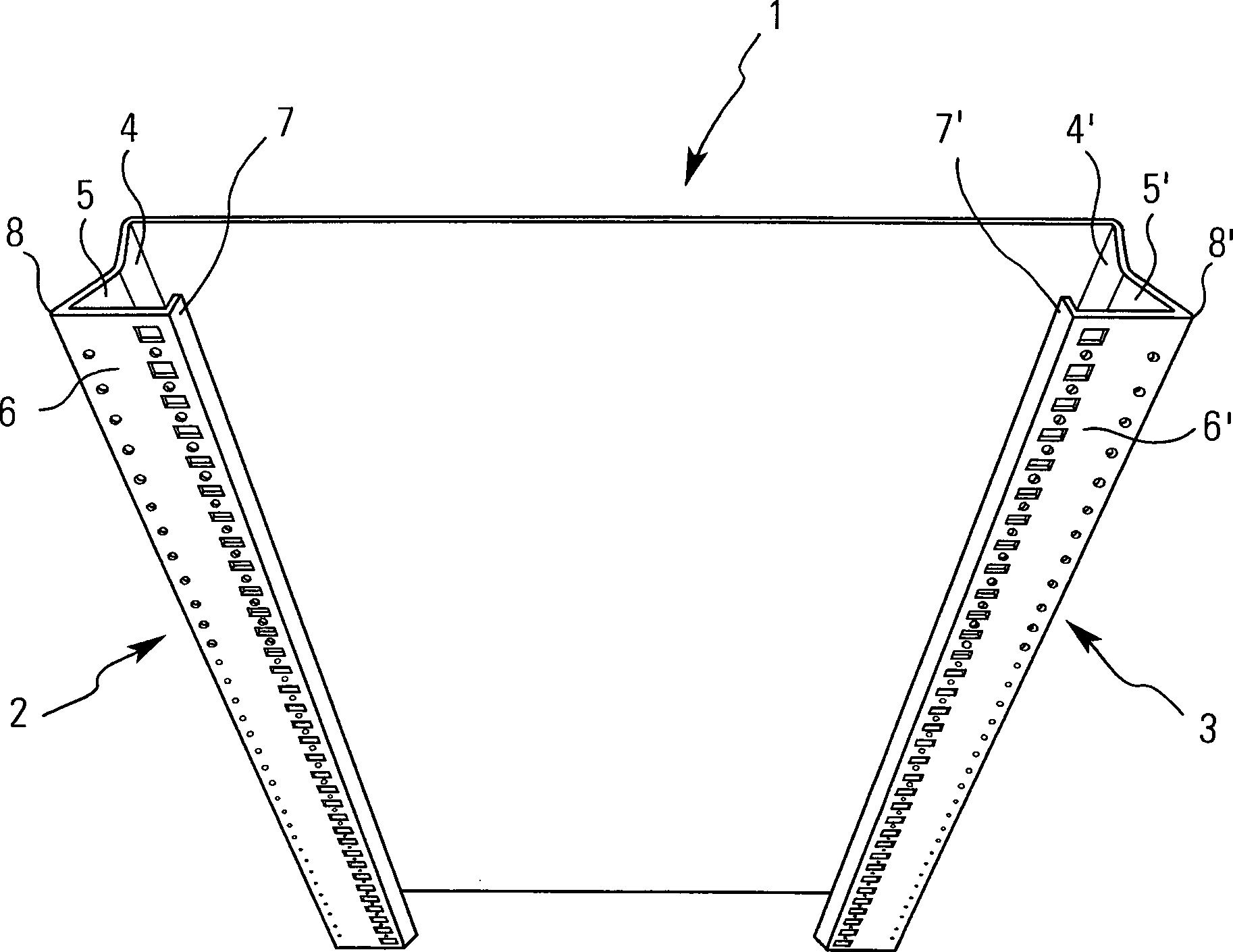
Die Erfindung wird nachfolgend anhand eines Ausführungsbeispieles unter Bezugnahme auf die Zeichnung näher erläutert. Es zeigen:The invention is described below of an embodiment explained in more detail with reference to the drawing. Show it:
Die beiden Profilränder
Im einzelnen weist jeder vertikale
Profilrand
Die einzelnen Kanten müssen hierbei nicht scharf umgebogen werden, kann hierbei an der jeweiligen Falz- oder Knickkante auch eine 45° -Fläche entstehen.The individual edges must be here cannot be bent sharply, can be a 45 ° surface.
Der dritte Abschnitt dient im eingebauten
Zustand als in den Schaltschrankinnenraum gerichtete Anlagefläche, an
welcher weitere Elemente befestigbar sind. Zu diesem Zweck sind
in dem dritten Anschnitt
Bei dem in
Der vertikale Profilrand
In
Im einzelnen werden hierbei durch
Umkanten vier Schenkel
Der erste Schenkel
Auch der obere horizontale Profilrand
Die beiden Anlageflächen der
Profilränder
Ein oberer horizontaler Profilrahmen
Das obere horizontale Rahmenprofil
Rechtwinklig zu dem Schenkel
Auch bei dem horizontalen Profil
Bei dem in
Das untere Randprofil
Auch das Randprofil
Das untere Rahmenprofil
Wie bereits ausgeführt werden
die Randprofile der Seitenwand
Die Seitenwand stellt durch die zusätzlichen Lochreihen ausreichend Befestigungsmöglichkeiten im inneren des Schaltschrankes zur Verfügung, wobei diese Lochreihen einfach zugänglich sind, ferner bieten die als offene Profile ausgebildeten Profilränder Möglichkeiten, weitere Bauelemente zu verstauen, z.B. Kabeln in den Profilrändern festzulegen.The side wall provides additional rows of holes sufficient mounting options in the interior of the control cabinet available, these rows of holes easily accessible furthermore, the profile edges designed as open profiles offer possibilities stow other components, e.g. Fix cables in the profile edges.
Claims (22)
Priority Applications (4)
| Application Number | Priority Date | Filing Date | Title |
|---|---|---|---|
| DE10143918A DE10143918B4 (en) | 2001-09-07 | 2001-09-07 | switch cabinet |
| PCT/EP2002/010087 WO2003023921A1 (en) | 2001-09-07 | 2002-09-09 | Switchgear cabinet |
| US10/489,079 US20050061644A1 (en) | 2001-09-07 | 2002-09-09 | Switch cabinet |
| EP02767479A EP1423895A1 (en) | 2001-09-07 | 2002-09-09 | Switchgear cabinet |
Applications Claiming Priority (1)
| Application Number | Priority Date | Filing Date | Title |
|---|---|---|---|
| DE10143918A DE10143918B4 (en) | 2001-09-07 | 2001-09-07 | switch cabinet |
Publications (2)
| Publication Number | Publication Date |
|---|---|
| DE10143918A1 DE10143918A1 (en) | 2003-04-17 |
| DE10143918B4 true DE10143918B4 (en) | 2004-05-06 |
Family
ID=7698068
Family Applications (1)
| Application Number | Title | Priority Date | Filing Date |
|---|---|---|---|
| DE10143918A Expired - Fee Related DE10143918B4 (en) | 2001-09-07 | 2001-09-07 | switch cabinet |
Country Status (4)
| Country | Link |
|---|---|
| US (1) | US20050061644A1 (en) |
| EP (1) | EP1423895A1 (en) |
| DE (1) | DE10143918B4 (en) |
| WO (1) | WO2003023921A1 (en) |
Families Citing this family (2)
| Publication number | Priority date | Publication date | Assignee | Title |
|---|---|---|---|---|
| DE102010016489B4 (en) * | 2010-04-16 | 2013-04-25 | Rittal Gmbh & Co. Kg | Housing part for a control cabinet |
| CN108462066B (en) * | 2018-05-30 | 2024-04-26 | 江苏荣威电气有限公司 | Energy-saving and environment-friendly switch cabinet |
Citations (3)
| Publication number | Priority date | Publication date | Assignee | Title |
|---|---|---|---|---|
| DE3731547A1 (en) * | 1987-09-19 | 1989-03-30 | Loh Kg Rittal Werk | SWITCH CABINET |
| DE29517924U1 (en) * | 1995-11-11 | 1997-03-13 | Klöckner-Moeller GmbH, 53115 Bonn | switch cabinet |
| DE29813780U1 (en) * | 1998-04-17 | 1998-10-01 | Rittal-Werk Rudolf Loh GmbH & Co. KG, 35745 Herborn | switch cabinet |
Family Cites Families (11)
| Publication number | Priority date | Publication date | Assignee | Title |
|---|---|---|---|---|
| JPS5577306A (en) * | 1978-12-04 | 1980-06-11 | Tokyo Shibaura Electric Co | Enclosed switchboard |
| US5574251A (en) * | 1995-02-15 | 1996-11-12 | Hendry Mechanical Works | Electrical and electronic cabinet systems |
| DE19506744C1 (en) * | 1995-02-27 | 1996-04-18 | Loh Kg Rittal Werk | Switch cabinet with vertically hinged access door |
| DE19614692C1 (en) * | 1996-04-13 | 1997-06-05 | Schroff Gmbh | Electronics cabinet |
| DE19647814C2 (en) * | 1996-11-19 | 1999-06-02 | Loh Kg Rittal Werk | switch cabinet |
| DE19647802C1 (en) * | 1996-11-19 | 1998-01-22 | Loh Kg Rittal Werk | Switch cabinet press-moulded mounting rail |
| US5889648A (en) * | 1997-07-25 | 1999-03-30 | Storage Technology Corporation | Seismic cabinet |
| DE19811714C2 (en) * | 1998-03-18 | 2000-04-13 | Loh Kg Rittal Werk | Kit for a control cabinet |
| DE19853611C1 (en) * | 1998-11-20 | 2000-04-06 | Skeppner Hans | Electrical equipment cabinet has attachment strip with a row of holes between sealing edges or surfaces, enabling covering elements to be attached without penetrating wall of frame profile |
| DE29904992U1 (en) * | 1999-03-18 | 1999-07-15 | Siemens AG, 80333 München | Cabinet to hold electronic assemblies and distribution components |
| DE19914408B4 (en) * | 1999-03-30 | 2006-07-13 | Deutsche Telekom Ag | equipment cabinet |
-
2001
- 2001-09-07 DE DE10143918A patent/DE10143918B4/en not_active Expired - Fee Related
-
2002
- 2002-09-09 WO PCT/EP2002/010087 patent/WO2003023921A1/en not_active Ceased
- 2002-09-09 EP EP02767479A patent/EP1423895A1/en not_active Withdrawn
- 2002-09-09 US US10/489,079 patent/US20050061644A1/en not_active Abandoned
Patent Citations (3)
| Publication number | Priority date | Publication date | Assignee | Title |
|---|---|---|---|---|
| DE3731547A1 (en) * | 1987-09-19 | 1989-03-30 | Loh Kg Rittal Werk | SWITCH CABINET |
| DE29517924U1 (en) * | 1995-11-11 | 1997-03-13 | Klöckner-Moeller GmbH, 53115 Bonn | switch cabinet |
| DE29813780U1 (en) * | 1998-04-17 | 1998-10-01 | Rittal-Werk Rudolf Loh GmbH & Co. KG, 35745 Herborn | switch cabinet |
Also Published As
| Publication number | Publication date |
|---|---|
| WO2003023921B1 (en) | 2003-07-31 |
| DE10143918A1 (en) | 2003-04-17 |
| EP1423895A1 (en) | 2004-06-02 |
| US20050061644A1 (en) | 2005-03-24 |
| WO2003023921A1 (en) | 2003-03-20 |
Similar Documents
| Publication | Publication Date | Title |
|---|---|---|
| EP0939984B1 (en) | Switching cabinet | |
| EP0939986B1 (en) | Switching cabinet with a rack | |
| EP0789984A1 (en) | Frame for a switchgear cabinet | |
| EP0404284A1 (en) | Framework for a switchbox consisting of a multiple of profiled elements, the said elements having a plurality of bends | |
| DE2609824A1 (en) | DEVICE FOR FASTENING ROLL-UP AWNINGS | |
| EP1719224A1 (en) | Kit for producing a frame superstructure for switchgear cabinets | |
| EP0939980B1 (en) | Rack with a lower frame and an upper frame made of a continuous section | |
| DE19934680C2 (en) | Metal door lock and frame with thermal bridge break | |
| DE202010000660U1 (en) | Kit for metal cabinets | |
| DD290030A5 (en) | WALL AND / OR CEILING ELEMENT | |
| DE8017644U1 (en) | CORNER ANGLE FOR CONNECTING TWO SPACER HOLE PROFILES OF AN INSULATED GLASS DISC | |
| EP0010291B1 (en) | Switch cabinet | |
| DE29902266U1 (en) | Rack for a 19 "distribution cabinet | |
| EP0478902B1 (en) | Shelf with folded reinforcement members | |
| DE29509555U1 (en) | Control cabinet with mounting plate as a single or modular cabinet | |
| DE10143918A1 (en) | switch cabinet | |
| DE102019128057A1 (en) | Building ventilation device for installation in a wall opening | |
| DE19535375C1 (en) | Mechanical coupling base element for switch-cabinet construction | |
| DE1778050A1 (en) | Rigid frame construction for racks, instrument housings, consoles, cabinets and the like. | |
| DE102007028008A1 (en) | Framework for edge joints, has frame parts formed so that side piece of edge joints are immersed completely into two neighboring frame parts and edge joints are enclosed by frame parts from exterior of framework | |
| DE3624331C1 (en) | Laboratory cabinet having a plurality of sheet-metal housing parts | |
| DE19949226B4 (en) | partition wall | |
| EP1037346A1 (en) | Rack of a cabinet | |
| DE10147978C1 (en) | Structural element for electrical or electronic apparatus frame or housing formed by bending single sheet metal plate | |
| AT410627B (en) | Metal cabinet |
Legal Events
| Date | Code | Title | Description |
|---|---|---|---|
| OP8 | Request for examination as to paragraph 44 patent law | ||
| 8181 | Inventor (new situation) |
Inventor name: ALTENA, HEINE, RIJSWIJK, NL |
|
| 8127 | New person/name/address of the applicant |
Owner name: ELDON HOLDING AB, RIJSWIJK, NL |
|
| 8364 | No opposition during term of opposition | ||
| 8327 | Change in the person/name/address of the patent owner |
Owner name: ELDON AB, NAESSJOE, SE |
|
| 8327 | Change in the person/name/address of the patent owner |
Owner name: ELDON HOLDING AB, NAESSJOE, SE |
|
| 8339 | Ceased/non-payment of the annual fee |