EP0477705B1 - Heizkessel - Google Patents
Heizkessel Download PDFInfo
- Publication number
- EP0477705B1 EP0477705B1 EP91115628A EP91115628A EP0477705B1 EP 0477705 B1 EP0477705 B1 EP 0477705B1 EP 91115628 A EP91115628 A EP 91115628A EP 91115628 A EP91115628 A EP 91115628A EP 0477705 B1 EP0477705 B1 EP 0477705B1
- Authority
- EP
- European Patent Office
- Prior art keywords
- gas
- combustion
- air
- heated
- burner
- Prior art date
- Legal status (The legal status is an assumption and is not a legal conclusion. Google has not performed a legal analysis and makes no representation as to the accuracy of the status listed.)
- Expired - Lifetime
Links
Images

Classifications
-
- F—MECHANICAL ENGINEERING; LIGHTING; HEATING; WEAPONS; BLASTING
- F23—COMBUSTION APPARATUS; COMBUSTION PROCESSES
- F23N—REGULATING OR CONTROLLING COMBUSTION
- F23N1/00—Regulating fuel supply
- F23N1/02—Regulating fuel supply conjointly with air supply
- F23N1/022—Regulating fuel supply conjointly with air supply using electronic means
-
- F—MECHANICAL ENGINEERING; LIGHTING; HEATING; WEAPONS; BLASTING
- F24—HEATING; RANGES; VENTILATING
- F24H—FLUID HEATERS, e.g. WATER OR AIR HEATERS, HAVING HEAT-GENERATING MEANS, e.g. HEAT PUMPS, IN GENERAL
- F24H1/00—Water heaters, e.g. boilers, continuous-flow heaters or water-storage heaters
- F24H1/22—Water heaters other than continuous-flow or water-storage heaters, e.g. water heaters for central heating
- F24H1/34—Water heaters other than continuous-flow or water-storage heaters, e.g. water heaters for central heating with water chamber arranged adjacent to the combustion chamber or chambers, e.g. above or at side
-
- F—MECHANICAL ENGINEERING; LIGHTING; HEATING; WEAPONS; BLASTING
- F23—COMBUSTION APPARATUS; COMBUSTION PROCESSES
- F23N—REGULATING OR CONTROLLING COMBUSTION
- F23N2221/00—Pretreatment or prehandling
- F23N2221/06—Preheating gaseous fuel
-
- F—MECHANICAL ENGINEERING; LIGHTING; HEATING; WEAPONS; BLASTING
- F23—COMBUSTION APPARATUS; COMBUSTION PROCESSES
- F23N—REGULATING OR CONTROLLING COMBUSTION
- F23N2225/00—Measuring
- F23N2225/08—Measuring temperature
-
- F—MECHANICAL ENGINEERING; LIGHTING; HEATING; WEAPONS; BLASTING
- F23—COMBUSTION APPARATUS; COMBUSTION PROCESSES
- F23N—REGULATING OR CONTROLLING COMBUSTION
- F23N2225/00—Measuring
- F23N2225/08—Measuring temperature
- F23N2225/13—Measuring temperature outdoor temperature
Definitions
- the invention relates to a boiler according to the preamble of the claim.
- the object of the invention is to provide a boiler of the type mentioned in the introduction, in which the intended air ratio can be maintained in a simple manner under all operating conditions, in particular during a cold start and stable continuous operation.
- both of the components provided for combustion are treated essentially the same, so that when the engine is cold started, the combustion air and the gas are heated essentially the same with continued operation. An essentially constant air ratio is thus achieved.
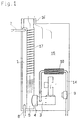
- FIG. 1 and 2 schematically show two embodiments of the invention.
- a heat exchanger 1 is arranged in a combustion chamber 5 and is connected to a heating water return 7 and a heating water supply 8.
- a gas burner 4 is preceded by a mixing chamber 3 which is separated from the combustion chamber 5 by a heat-conducting wall Room 15 is arranged, in which combustion air can flow in via an opening 16. This is heated in the room 15 by the heat radiation from a wall 17 of the heat exchanger 1 and by direct heat exchange with the wall 17.
- a section of the gas pipe 14 is guided within the space 15 and is designed as a finned pipe 10. This ensures a good heat exchange between the combustion air in the space 15, in which it is heated via the wall 17, and the gas flowing in the finned tube 10, so that this is also heated.
- the embodiment according to FIG. 2 differs from that according to FIG. 1 essentially in that a section of the finned gas pipe 14 is led directly through the combustion chamber 5.
Landscapes
- Engineering & Computer Science (AREA)
- Chemical & Material Sciences (AREA)
- Combustion & Propulsion (AREA)
- Mechanical Engineering (AREA)
- General Engineering & Computer Science (AREA)
- Physics & Mathematics (AREA)
- Thermal Sciences (AREA)
- Air Supply (AREA)
- Steam Or Hot-Water Central Heating Systems (AREA)
- Yarns And Mechanical Finishing Of Yarns Or Ropes (AREA)
- Control Of Combustion (AREA)
- Regulation And Control Of Combustion (AREA)
Description
- Die Erfindung bezieht sich auf einen Heizkessel gemäß dem Oberbegriff des Patentanspruchs.
- Bei solchen Heizkesseln, insbesondere solchen mit Vormischgasbrennern, bei denen die Verbrennungsluft oder das Brenngas vor dem Einströmen in die Brennkammer mit im Betriebszustand erwärmten Teilen in Berührung und damit in einem Wärmeaustausch kommt - beispielsweise gemäß der FR-OS 24 11 365 oder der FR-OS 78 79 12 -, kommt es aufgrund der starken Abhängigkeit des Massenverhältnisses zwischen Gas und Luft von der Temperatur dieser beiden Komponenten zu einer Veränderung der Luftzahl zu Beginn eines jeden Betriebes. Dies führt zu Betriebsproblemen. So bewirken hohe Luftzahlen bei Kaltstarts instabile Flammen, niedrige Ionisationsströme und eine Zündunwilligkeit des Gas-Luft-Gemisches. Bei Dauerbetrieb führen andererseits zu niedrige Luftzahlen zu hohen CO- und NOX-Emissionen.
- Um eine Vergleichmäßigung des Gas-Luft-Verhältnisses bei allen Betriebsbedingungen zu erreichen, wurde gemäß der GB-OS 20 49 131 für einen Industrieofen vorgeschlagen, einen rekuperativen Verbrennungsluftvorwärmer und einen Folgerekuperator als Brenngasvorwärmer einzusetzen.
- Aufgabe der Erfindung ist es, einen Heizkessel der eingangs erwähnten Art anzugeben, bei dem die vorgesehene Luftzahl bei allen Betriebsbedingungen, insbesondere bei Kaltstart und stabilem Dauerbetrieb, auf einfache Art und Weise eingehalten werden kann.
- Erfindungsgemäß wird dies durch die kennzeichnenden Merkmale des Patentanspruchs erreicht.
- Durch diese Maßnahmen ist sichergestellt, daß die Verbrennungsluft und das zur Verbrennung vorgesehene Gas im Betrieb des Brenners synchron erwärmt werden. Erfindungsgemäß werden beide zur Verbrennung vorgesehene Komponenten im wesentlichen gleich behandelt, so daß bei einem Kaltstart eine im wesentlichen gleiche Erwärmung der Verbrennungsluft und des Gases mit der Fortdauer des Betriebes erfolgt. Damit wird eine im wesentlichen gleichbleibende Luftzahl erreicht.
- Die Erfindung wird nun anhand der Zeichnung näher erläutert.
- Dabei zeigen:
- Fig. 1 und 2 schematisch zwei Ausführungsformen der Erfindung.
- Bei der Ausführungsform nach der Fig. 1 ist in einer Brennkammer 5 ein Wärmetauscher 1 angeordnet, der mit einem Heizwasserrücklauf 7 und einem Heizwasservorlauf 8 verbunden ist. Einem Gasbrenner 4 ist eine Mischkammer 3 vorgeschaltet, die in einem von der Brennkammer 5 über eine wärmeleitende Wand getrennten Raum 15 angeordnet ist, in den Verbrennungsluft über eine Öffnung 16 einströmen kann. Diese wird in dem Raum 15 durch die Wärmestrahlung einer Wand 17 des Wärmetauschers 1 und durch direkten Wärmeaustausch mit der Wand 17 erwärmt.
- Ein Abschnitt des Gasrohres 14 ist innerhalb des Raumes 15 geführt und als Rippenrohr 10 ausgebildet. Dadurch ist ein guter Wärmeaustausch zwischen der Verbrennungsluft im Raum 15, in dem diese über die Wand 17 erwärmt wird, und dem im Rippenrohr 10 strömenden Gas sichergestellt, so daß auch dieses erwärmt wird.
- Die Ausführungsform nach der Fig. 2 unterscheidet sich von jener nach den Fig. 1 im wesentlichen dadurch, daß ein Abschnitt des berippten Gasrohres 14 unmittelbar durch die Brennkammer 5 geführt ist.
Claims (1)
- Heizkessel mit einem Wärmetauscher (1) und einem in einer Brennkammer (5) angeordneten Gasbrenner (4), vorzugsweise einem Vormischgasbrenner, mit einer Leitung (16/15) zur Führung der Verbrennungsluft und einer Gasleitung (14) sowie einer Abgasleitung, wobei die Verbrennungsluftleitung (16/15) und die Gasleitung (14) zumindest abschnittsweise von im Betriebszustand des Gasbrenners (4) erwärmten Teilen, wie Brennkammer (5), Wärmetauscher (1) usw. derart begrenzt sind, daß eine im wesentlichen gleiche Erwärmung der Verbrennungsluft und des Gases erfolgt, dadurch gekennzeichnet, daß die Gasleitung (14) abschnittsweise als Rippenrohr (10) ausgebildet ist, das in dem von der Verbrennungsluft durchströmten und von einer Wand (17) der Brennkammer (5) begrenzten Raum (15) oder innerhalb der Brennkammer (5) angeordnet ist.
Applications Claiming Priority (4)
| Application Number | Priority Date | Filing Date | Title |
|---|---|---|---|
| DE9013534 | 1990-09-22 | ||
| DE9013534U | 1990-09-22 | ||
| AT0243590A AT399933B (de) | 1990-12-03 | 1990-12-03 | Heizkessel |
| AT2435/90 | 1990-12-03 |
Publications (3)
| Publication Number | Publication Date |
|---|---|
| EP0477705A2 EP0477705A2 (de) | 1992-04-01 |
| EP0477705A3 EP0477705A3 (en) | 1992-11-19 |
| EP0477705B1 true EP0477705B1 (de) | 1996-04-17 |
Family
ID=25598452
Family Applications (1)
| Application Number | Title | Priority Date | Filing Date |
|---|---|---|---|
| EP91115628A Expired - Lifetime EP0477705B1 (de) | 1990-09-22 | 1991-09-14 | Heizkessel |
Country Status (3)
| Country | Link |
|---|---|
| EP (1) | EP0477705B1 (de) |
| AT (1) | ATE137003T1 (de) |
| DE (2) | DE9111583U1 (de) |
Families Citing this family (3)
| Publication number | Priority date | Publication date | Assignee | Title |
|---|---|---|---|---|
| DE4223799C2 (de) * | 1992-07-20 | 1997-01-30 | Dejatech Bv | Gasheizgerät |
| AT403199B (de) * | 1994-08-03 | 1997-11-25 | Vaillant Gmbh | Heizgerät |
| NO306483B1 (no) * | 1997-12-05 | 1999-11-08 | Forsvarets Forsknings | Anordning ved mate- og dyse-systemet for en brenner av primus-typen |
Family Cites Families (4)
| Publication number | Priority date | Publication date | Assignee | Title |
|---|---|---|---|---|
| FR787912A (fr) * | 1934-06-30 | 1935-10-01 | Usines De Rosieres | Perfectionnements aux appareils de chauffage utilisant des hydrocarbures gazeux |
| DE7737272U1 (de) * | 1977-12-07 | 1983-02-03 | Joh. Vaillant Gmbh U. Co, 5630 Remscheid | Feuerstaette |
| DE2920902A1 (de) * | 1979-05-23 | 1981-04-09 | Loi Industrieofenanlagen Gmbh, 4300 Essen | Vorrichtung zum beheizen eines industrieofens |
| NL8702303A (nl) * | 1987-09-25 | 1989-04-17 | Wetering Gemeenschappelijk Bez | Verwarmingstoestel. |
-
1991
- 1991-09-14 EP EP91115628A patent/EP0477705B1/de not_active Expired - Lifetime
- 1991-09-14 DE DE9111583U patent/DE9111583U1/de not_active Expired - Lifetime
- 1991-09-14 DE DE59107680T patent/DE59107680D1/de not_active Expired - Fee Related
- 1991-09-14 AT AT91115628T patent/ATE137003T1/de not_active IP Right Cessation
Also Published As
| Publication number | Publication date |
|---|---|
| ATE137003T1 (de) | 1996-05-15 |
| EP0477705A2 (de) | 1992-04-01 |
| DE59107680D1 (de) | 1996-05-23 |
| DE9111583U1 (de) | 1991-11-21 |
| EP0477705A3 (en) | 1992-11-19 |
Similar Documents
| Publication | Publication Date | Title |
|---|---|---|
| DE2841105C2 (de) | Vergasungsbrenner | |
| EP0307538A2 (de) | Feuerungseinrichtung | |
| DE2457963A1 (de) | Heissgasgenerator | |
| EP0021035B1 (de) | Verfahren zum Betrieb von Vormischbrennern und Brenner zur Durchführung des Verfahrens | |
| DE2742070A1 (de) | Industriebrenner zur beheizung von ofenraeumen in industrieoefen | |
| DE2700671C2 (de) | Blaubrennender Ölbrenner | |
| DE2157526A1 (de) | Brennersystem für Brennstoffgemische | |
| DE3343617A1 (de) | Ultraschallzerstaeuber-brenner fuer kleinere heizgeraete | |
| EP0477705B1 (de) | Heizkessel | |
| DE4417417A1 (de) | Brenneranordnung | |
| EP0578131A1 (de) | Warmwasserbereiter mit katalytischem Brenner | |
| EP0078876A1 (de) | Verfahren und Vorrichtung zum Erhitzen von Verbrennungsluft und Brennstoff in Heizungsanlagen | |
| AT402847B (de) | Wärmeerzeuger mit einem teilweise katalytisch beschichteten metallischen wabenkörperreaktor | |
| EP0663563A1 (de) | Verbrennungsgasführung | |
| EP0266377B2 (de) | Heizungsgerät mit nachbrenner | |
| AT399933B (de) | Heizkessel | |
| DE4308017C1 (de) | Wassererwärmer mit katalytischem Brenner und Verfahren zu seinem Betreiben | |
| DE3420408C2 (de) | Brenner zum Verbrennen von Abgasen | |
| DE3243399A1 (de) | Vorrichtung mit brenner und waermetauscher | |
| EP0287596A1 (de) | Brenner für die verbrennung von flüssigem brennstoff. | |
| DE19645143A1 (de) | Katalytischer Wärmeerzeuger sowie ein Verfahren zum Betreiben eines derartigen Wärmeerzeugers | |
| DE3042307C2 (de) | Einsatz für Öfen oder Heizkessel | |
| EP0529474A2 (de) | Einrichtung zur Wärmeerzeugung durch katalytische Verbrennung | |
| DE4225557A1 (de) | Sekundärbrennkammer für Gebläsebrenner | |
| DE3006048A1 (de) | Verfahren zum betrieb einer heizkesselanlage und dafuer geeignete vorrichtung |
Legal Events
| Date | Code | Title | Description |
|---|---|---|---|
| PUAI | Public reference made under article 153(3) epc to a published international application that has entered the european phase |
Free format text: ORIGINAL CODE: 0009012 |
|
| AK | Designated contracting states |
Kind code of ref document: A2 Designated state(s): AT BE CH DE DK ES FR GB GR IT LI LU NL SE |
|
| PUAL | Search report despatched |
Free format text: ORIGINAL CODE: 0009013 |
|
| AK | Designated contracting states |
Kind code of ref document: A3 Designated state(s): AT BE CH DE DK ES FR GB GR IT LI LU NL SE |
|
| 17P | Request for examination filed |
Effective date: 19930512 |
|
| 17Q | First examination report despatched |
Effective date: 19930906 |
|
| RAP1 | Party data changed (applicant data changed or rights of an application transferred) |
Owner name: VAILLANT GMBH Owner name: VAILLANT B.V. Owner name: VAILLANT LTD. Owner name: VAILLANT GES.M.B.H Owner name: VAILLANT S.A.R.L Owner name: N.V. VAILLANT S.A. Owner name: JOH. VAILLANT GMBH U. CO. |
|
| GRAH | Despatch of communication of intention to grant a patent |
Free format text: ORIGINAL CODE: EPIDOS IGRA |
|
| GRAA | (expected) grant |
Free format text: ORIGINAL CODE: 0009210 |
|
| AK | Designated contracting states |
Kind code of ref document: B1 Designated state(s): AT BE CH DE DK ES FR GB GR IT LI LU NL SE |
|
| PG25 | Lapsed in a contracting state [announced via postgrant information from national office to epo] |
Ref country code: GR Free format text: LAPSE BECAUSE OF FAILURE TO SUBMIT A TRANSLATION OF THE DESCRIPTION OR TO PAY THE FEE WITHIN THE PRESCRIBED TIME-LIMIT Effective date: 19960417 Ref country code: ES Free format text: THE PATENT HAS BEEN ANNULLED BY A DECISION OF A NATIONAL AUTHORITY Effective date: 19960417 Ref country code: DK Effective date: 19960417 |
|
| REF | Corresponds to: |
Ref document number: 137003 Country of ref document: AT Date of ref document: 19960515 Kind code of ref document: T |
|
| REF | Corresponds to: |
Ref document number: 59107680 Country of ref document: DE Date of ref document: 19960523 |
|
| ITF | It: translation for a ep patent filed | ||
| PG25 | Lapsed in a contracting state [announced via postgrant information from national office to epo] |
Ref country code: SE Effective date: 19960717 |
|
| GBT | Gb: translation of ep patent filed (gb section 77(6)(a)/1977) |
Effective date: 19960716 |
|
| ET | Fr: translation filed | ||
| PG25 | Lapsed in a contracting state [announced via postgrant information from national office to epo] |
Ref country code: LU Free format text: LAPSE BECAUSE OF NON-PAYMENT OF DUE FEES Effective date: 19960930 |
|
| PLBE | No opposition filed within time limit |
Free format text: ORIGINAL CODE: 0009261 |
|
| STAA | Information on the status of an ep patent application or granted ep patent |
Free format text: STATUS: NO OPPOSITION FILED WITHIN TIME LIMIT |
|
| 26N | No opposition filed | ||
| ITF | It: translation for a ep patent filed | ||
| PGFP | Annual fee paid to national office [announced via postgrant information from national office to epo] |
Ref country code: FR Payment date: 19990609 Year of fee payment: 9 |
|
| PGFP | Annual fee paid to national office [announced via postgrant information from national office to epo] |
Ref country code: GB Payment date: 19990614 Year of fee payment: 9 |
|
| PGFP | Annual fee paid to national office [announced via postgrant information from national office to epo] |
Ref country code: NL Payment date: 19990628 Year of fee payment: 9 |
|
| PGFP | Annual fee paid to national office [announced via postgrant information from national office to epo] |
Ref country code: AT Payment date: 19990811 Year of fee payment: 9 |
|
| PGFP | Annual fee paid to national office [announced via postgrant information from national office to epo] |
Ref country code: CH Payment date: 19990827 Year of fee payment: 9 |
|
| PGFP | Annual fee paid to national office [announced via postgrant information from national office to epo] |
Ref country code: DE Payment date: 19990923 Year of fee payment: 9 |
|
| PGFP | Annual fee paid to national office [announced via postgrant information from national office to epo] |
Ref country code: BE Payment date: 19991026 Year of fee payment: 9 |
|
| PG25 | Lapsed in a contracting state [announced via postgrant information from national office to epo] |
Ref country code: GB Free format text: LAPSE BECAUSE OF NON-PAYMENT OF DUE FEES Effective date: 20000914 Ref country code: AT Free format text: LAPSE BECAUSE OF NON-PAYMENT OF DUE FEES Effective date: 20000914 |
|
| PG25 | Lapsed in a contracting state [announced via postgrant information from national office to epo] |
Ref country code: LI Free format text: LAPSE BECAUSE OF NON-PAYMENT OF DUE FEES Effective date: 20000930 Ref country code: CH Free format text: LAPSE BECAUSE OF NON-PAYMENT OF DUE FEES Effective date: 20000930 Ref country code: BE Free format text: LAPSE BECAUSE OF NON-PAYMENT OF DUE FEES Effective date: 20000930 |
|
| BERE | Be: lapsed |
Owner name: S.A. VAILLANT N.V. Effective date: 20000930 |
|
| PG25 | Lapsed in a contracting state [announced via postgrant information from national office to epo] |
Ref country code: NL Free format text: LAPSE BECAUSE OF NON-PAYMENT OF DUE FEES Effective date: 20010401 |
|
| GBPC | Gb: european patent ceased through non-payment of renewal fee |
Effective date: 20000914 |
|
| REG | Reference to a national code |
Ref country code: CH Ref legal event code: PL |
|
| PG25 | Lapsed in a contracting state [announced via postgrant information from national office to epo] |
Ref country code: FR Free format text: LAPSE BECAUSE OF NON-PAYMENT OF DUE FEES Effective date: 20010531 |
|
| NLV4 | Nl: lapsed or anulled due to non-payment of the annual fee |
Effective date: 20010401 |
|
| PG25 | Lapsed in a contracting state [announced via postgrant information from national office to epo] |
Ref country code: DE Free format text: LAPSE BECAUSE OF NON-PAYMENT OF DUE FEES Effective date: 20010601 |
|
| REG | Reference to a national code |
Ref country code: FR Ref legal event code: ST |
|
| PG25 | Lapsed in a contracting state [announced via postgrant information from national office to epo] |
Ref country code: IT Free format text: LAPSE BECAUSE OF NON-PAYMENT OF DUE FEES Effective date: 20050914 |