EP0476236B1 - Dispositif d'accouplement sur le moule d'une machine à mouler par injection de matière plastique - Google Patents
Dispositif d'accouplement sur le moule d'une machine à mouler par injection de matière plastique Download PDFInfo
- Publication number
- EP0476236B1 EP0476236B1 EP91110005A EP91110005A EP0476236B1 EP 0476236 B1 EP0476236 B1 EP 0476236B1 EP 91110005 A EP91110005 A EP 91110005A EP 91110005 A EP91110005 A EP 91110005A EP 0476236 B1 EP0476236 B1 EP 0476236B1
- Authority
- EP
- European Patent Office
- Prior art keywords
- coupling
- mould
- movable
- assembly according
- actuating
- Prior art date
- Legal status (The legal status is an assumption and is not a legal conclusion. Google has not performed a legal analysis and makes no representation as to the accuracy of the status listed.)
- Expired - Lifetime
Links
Images
Classifications
-
- B—PERFORMING OPERATIONS; TRANSPORTING
- B29—WORKING OF PLASTICS; WORKING OF SUBSTANCES IN A PLASTIC STATE IN GENERAL
- B29C—SHAPING OR JOINING OF PLASTICS; SHAPING OF MATERIAL IN A PLASTIC STATE, NOT OTHERWISE PROVIDED FOR; AFTER-TREATMENT OF THE SHAPED PRODUCTS, e.g. REPAIRING
- B29C45/00—Injection moulding, i.e. forcing the required volume of moulding material through a nozzle into a closed mould; Apparatus therefor
- B29C45/17—Component parts, details or accessories; Auxiliary operations
- B29C45/26—Moulds
- B29C45/33—Moulds having transversely, e.g. radially, movable mould parts
- B29C45/332—Mountings or guides therefor; Drives therefor
-
- B—PERFORMING OPERATIONS; TRANSPORTING
- B29—WORKING OF PLASTICS; WORKING OF SUBSTANCES IN A PLASTIC STATE IN GENERAL
- B29C—SHAPING OR JOINING OF PLASTICS; SHAPING OF MATERIAL IN A PLASTIC STATE, NOT OTHERWISE PROVIDED FOR; AFTER-TREATMENT OF THE SHAPED PRODUCTS, e.g. REPAIRING
- B29C33/00—Moulds or cores; Details thereof or accessories therefor
- B29C33/0083—Electrical or fluid connection systems therefor
Definitions
- the invention relates to a coupling device according to the preamble of claim 1.
- Machine coupling in the sense of the generic term is understood to mean that coupling which is carried by the mold carrier when the injection mold is closed or opened, that is to say moves with it.
- temperature control When operating plastic injection molding machines, it is necessary to bring the injection mold to the optimum operating temperature for the production of the molded parts before starting the injection operation. This measure is referred to below as temperature control of the injection mold.
- a heat transfer liquid is pumped through appropriate temperature control channels in the mold halves.
- electrical energy for. B. to supply for thermal sensors.
- the temperature control is often carried out on the injection mold already arranged in the operating position, that is to say in the clamping space of the plastic injection molding machine.
- Such a construction of the coupling device results in a production-friendly, largely symmetrical construction of the couplings on the injection mold; on the other hand there is a spatial temporal separation of the connection of the supply lines for the Temperature control on the one hand and the supply lines for the operational functions on the other hand not possible.
- the prospective buyer only has the option of purchasing the coupling device designed for temperature control and for all operational functions as a complete package, even if there is no need for certain operational functions.
- the known device requires a hydraulic drive cylinder for moving one coupling half to the other and a further drive cylinder for locking the coupling.
- the transfer of the injection mold with coupled supply lines from the shuttle table into the clamping area of the injection molding machine and vice versa requires flexible, freely movable end sections of the machine-side supply lines, which move with the transfer of the injection mold.
- further couplings for operational functions are coupled with the aid of the insertion movement when the injection mold is retracted horizontally into the clamping space.
- concentricity of the coupling parts is not guaranteed.
- the force of the insertion movement is often not sufficient for a safe coupling.
- the known device has the advantage that a change Injection mold can be tempered to operating temperature on a shuttle table, while the injection operation continues with the injection mold still to be replaced. Since the temperature of the injection mold can often take more than an hour, this results in a significant reduction in changeover times when changing the mold.
- the invention has for its object to provide a coupling device of the type mentioned in such a way that the coupling means provided with their own drive for the temperature control and the coupling means provided with their own drive for the required operational functions of the injection mold are arranged separately from one another and thereby according to scope and location can be better adapted to respective needs.
- the possibility is to be opened to carry out the temperature control outside the injection molding machine and still only connect supply lines for operational functions to the injection mold that has been moved into the working position with a single drive cylinder and requires little space if there is a need for this.
- the coupling direction of the movable coupling half runs perpendicular to the parting plane of the injection mold, ie horizontally.
- Such a separation of coupling agents for the tempering of Coupling means for the operational functions is advantageous insofar as supply lines for the temperature control from the supply sources in the area of the injection molding machine to the transfer table are to be carried out, however, in the case of supply lines for operational functions, laying over a relatively short distance to the clamping area is sufficient. Accordingly, the coupling means to be coupled on the shuttle table can be dimensioned smaller. The smaller dimensions, combined with a reduction in the number of supply lines to be coupled, in turn facilitate the transfer of the injection mold from the shuttle table to the clamping area and vice versa. Due to the described concept of supplying energy to the injection mold, it is possible when the plastic injection molding machine is delivered to equip it with more or fewer coupling agents as required.
- the coupling device takes up relatively little space and manages with a single drive that realizes a clamping path and a coupling path per coupling.
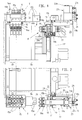
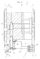
- the mold halves Sa and Sb of the injection mold S can be clamped by means of contact plates 11 onto the mold carriers 13, 13 '(FIGS. 1, 2, 9) of a mold-closing unit of the plastic injection molding machine.
- the coupling device ensures the connection of supply lines to the injection mold S when they are tempered and when the operative mold functions are carried out, such as, for example, when hydraulically pulling cores, the compressed air output of injection molded parts and the output of signals.
- a coupling half 26, 28a with a machine-side coupling half 27, 28b forms the movable coupling F for supply lines for operational functions of the injection mold.
- the coupling half 27, 28b comprises an upper hydraulic coupling part 27 and a lower electrical coupling part 28b.
- a coupling half 14 with a machine-side coupling half 15 forms a stationary coupling T for supply lines for the temperature control of the injection mold.
- a hydraulic drive cylinder is provided for each of the movable coupling and the stationary coupling, through the drive stroke of which the coupling halves 27, 28b; 15 to the coupling halves 26, 28a; 14 can be coupled or uncoupled.
- the coupling T arranged in the area of the stationary mold half Sa is for the temperature control of the injection mold and the coupling F arranged in the area of the movable mold halves Sb is essentially determined and suitable for the execution of operative mold functions.
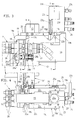
- Figures 1 to 8 show the temperature previously and on a shuttle table Thereafter, the injection mold is moved into the clamping area of the injection molding machine, in which the stationary coupling T is already closed on the changing table at the beginning of the temperature control and remains in the closed state when entering the clamping area.
- the coupling direction of the stationary coupling T fastened in the region of the stationary mold half Sa runs parallel to the parting plane tt of the injection mold S.
- the coupling direction of the movable coupling F arranged in the region of the movable mold half Sb runs perpendicular to the parting plane tt.
- the contact plates 11 project beyond the mold body of the injection mold S backwards.
- the coupling halves 14, 26 on the casting mold side are each arranged in the region of the sections of the contact plates 11 projecting beyond the casting mold body.
- One mold-side coupling half 14 is fastened to the upper edge of the contact plate 11 of the stationary mold half Sa, the other mold-side coupling half 26 is fastened to a connecting plate 18 fastened to the movable mold carrier 13 '.
- This connecting plate 18 is, as can be seen in particular from FIG. 2, partially embedded in a corresponding recess in the contact plate 11.
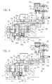
- the direction of the drive stroke of the hydraulic drive cylinders 23, 15a of the coupling direction is perpendicular to the coupling direction of the driven coupling halves.
- the force vector of the drive stroke is deflected by 90 ° by means of control plates 25, which are provided with oblique control grooves 25a.
- the control plates 25 are connected to the piston rod 23e of the drive cylinder 23 by means of a bearing axis 23h.
- control pins 22b of a slide 22 carrying the associated coupling halves 27, 28b engage in the oblique control grooves 25a of the control plates 25.
- the carriage 22 with its coupling halves 27, 28b forms a structural unit with the carrier element 19 carrying the drive cylinder 23. This unit is in one with the movable mold carrier 13 Bolt 21 fixed vertical bearing plate 20 mounted horizontally displaceable. It can be used by screwing the bearing plate 20 onto the mold carrier 13 'of the injection mold S which is in the working position.
- the figures 1-5 show the unit mentioned before it is braced with the connecting plate 18, each with the clutch not yet closed.
- the carriage receives the coupling halves 27, 28b with a plate-shaped vertical support part 22a facing the casting mold S.
- Two horizontal legs 22c of the carriage extend rearward from this carrier part 22a.
- the carriage 22 is guided horizontally on guide ribs 19c of the support element 19 which supports the drive cylinder 23.
- Cylinder 23f of the drive cylinder 23 is connected by means of fastening screws 23g to bearing bases 19d of the carrier element 19 (FIG. 3).
- the piston 23d of the drive cylinder 23 delimits cylinder spaces 23b which can be filled with pressure medium via hydraulic connections 23c.
- 23a is a cylinder cover closing the rear cylinder space and 24 limit switches for controlling the drive cylinder 23.
- the elongated support element 19 is supported on the bearing plate 20 by means of side projections 19b by means of screw bolts, which screw bolts 29, as will be explained further below, serve as travel limiting elements.
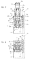
- the drive stroke of the drive cylinder 23 arranged in the region of the movable mold carrier 13 can be converted into a coupling path for coupling the machine-side coupling half 27, 28b and a clamping path for bracing the carrier element 19 carrying the drive cylinder with the movable mold half Sb.
- the coupling path is limited by means of a path limiting groove 20a in the bearing plate 20. In the path limiting groove 20a the control pin 22b of the carriage 22 penetrating the control groove 25a of the adjacent control plate 25 is immersed.
- the clamping path is limited by means of a path limiting recesses 20b (FIG. 4) in the bearing plate 20.
- Path limiting elements 29 of the carrier element 19 are immersed in the limiting recesses 20b with a play corresponding to the clamping path, as can be seen in particular from FIG. 4.
- the coupling members 27a, 28b '(FIG. 3) of the driven machine-side coupling halves 27, 28b couple with the coupling members 26a, 28a' (FIG. 3.5) of the mold-side coupling halves 26, 28a.
- the carriage 22 with its coupling half 27, 28b and the carrier element 19 with its rear engagement lug 19a move from a position according to FIG. 5 into a position according to FIG. 6.
- the carrier element 19 moves according to the play in the Path limiting recess 20b slightly to the right, the rear engagement lug 19a resting against the end face of the connecting plate 18.
- the carriage 22 moves to the left in accordance with the length of the path limiting groove 20a (FIG. 4) until the control pin 22b strikes the left edge of the path limiting groove 20a.
- the horizontal movement of the carrier element 19 is also forced during the drive stroke of the hydraulic cylinder 23 in accordance with the play in the travel-limiting recess 20b.
- the machine-side coupling part 28b is buffered on the back by means of coil springs.
- the coupling half 27; 28b and its carrier (slide 22) and the associated hydraulic drive cylinder 23 and its carrier (carrier element 19) existing and by means of the connecting plate 18 on the movable mold carrier 13 'supported displaceable structural unit after completion of the coupling with the contact plate 11 of the injection mold firmly clamped.
- the nose 19a of the carrier element 19 engages on one side of the contact plate 11 and the carrier part 22a for the coupling half 27; 28b of the slide 22 on the other side of the contact plate 11.
- the aforementioned tensioning and coupling operation therefore presupposes that the drive stroke of the hydraulic drive cylinder 23 is converted into an opposite movement of the carrier element 19 and the slide 22.
- the tensioning movement of the carrier element 19 can be relatively small and the tensioning movement of the slide 20 can be correspondingly large - or vice versa.
- the mentioned clamping movements can take place simultaneously or in succession, depending on the friction that occurs.
- FIG. 9 illustrates the supply of a hydraulic cylinder 30 controlling a metal core 31 via the coupling half 26 on the casting mold side and connecting lines 33 with pressure medium.
- the axis of the hydraulic cylinder 30 with piston rod 30a and actual cylinder 30b lies in the parting plane t-t and runs horizontally.
- the core 31 is already pulled out of the finished molded part 32.
- 15e denotes the machine-side connections of the supply lines to the coupling T and 14a the mold-side connections of the supply lines to the casting-mold side coupling half 14.
- the machine-side clutch half 15 is on the guide bolts 34 guided vertically. These are at the top by means of engagement elements 34a on one. Bridge of the changing table and with lower rear engaging members 34b on the mold-side coupling half 14 can be supported, where they engage in a guide groove 16 of the coupling half 14.
- the deflection of the force vector of the drive stroke of the drive cylinder 15a for the stationary clutch T is effected by technical means analogous to the drive cylinder 23 for the movable clutch F.
Landscapes
- Engineering & Computer Science (AREA)
- Mechanical Engineering (AREA)
- Manufacturing & Machinery (AREA)
- Injection Moulding Of Plastics Or The Like (AREA)
- Moulds For Moulding Plastics Or The Like (AREA)
Claims (9)
- Dispositif d'accouplement sur le moule (S), pourvu de plateaux d'application (11), d'une presse d'injection de matière plastique, dispositif qui est conçu et approprié tant pour l'alimentation de fluides d'équilibrage de température que pour l'accomplissement de fonctions d'exploitation du moule, comme par exemple le tirage hydraulique de noyaux, l'éjection par air comprimé de pièces moulées, la délivrance de signaux et similaires,
avec un demi-accouplement (26, 28a) qui est fixé sur le demi-moule mobile (Sb) et forme avec un demi-accouplement (27, 28b) prévu sur la presse un accouplement mobile (F) pour le raccordement de conduites d'alimentation, et avec un demi-accouplement (14) qui est fixé sur le demi-moule stationnaire (Sa) et forme avec un demi-accouplement (15) prévu sur la presse un accouplement stationnaire (T) pour le raccordement de conduites d'alimentation,
et avec des vérins hydrauliques d'entraînement (23; 15a) qui permettent de coupler les deux accouplements précités (F; T) au cours d'une course d'entraînement en fonction du programme du calculateur de commande de la presse d'injection, les plateaux d'application (11) du moule (S) dépassant du corps du moule et les demi-accouplements (14; 26) prévus sur le moule pouvant être respectivement fixés dans la région des parties dépassantes des plateaux d'application (11),
caractérisé en ce que l'accouplement mobile (F) est conçu pour accoupler ou désaccoupler des conduites d'alimentation pour l'accomplissement de fonctions d'exploitation du moule et l'accouplement stationnaire (T) est conçu pour accoupler ou désaccoupler des conduites d'alimentation pour le fluide d'équilibrage de température destiné à l'équilibrage de la température des deux demi-moules (Sa; Sb), la direction d'accouplement de l'accouplement mobile (F) s'étend perpendiculairement au plan de séparation (t-t) du moule (S), et la course d'entraînement du vérin d'entraînement (23) peut être transformée en une course d'accouplement pour l'accouplement du demi-accouplement (27) prévu sur la presse, et une course de serrage, de direction opposée, pour l'assemblage par serrage de l'élément porteur (19) du vérin d'entraînement (23) avec le demi-moule mobile (Sb). - Dispositif d'accouplement selon la revendication 1, caractérisé en ce que la direction d'accouplement de l'accouplement stationnaire (T) s'étend parallèlement au plan de séparation (t-t) du moule (S).
- Dispositif d'accouplement selon la revendication 1 ou 2, caractérisé en ce que l'un (14) des demi-accouplements prévus sur le moule peut être fixé sur le bord supérieur du plateau d'application (11) du demi-moule stationnaire (Sa), et l'autre demi-accouplement (26) prévu sur le moule peut être fixé sur une plaque de raccordement (18) fixée sur le plateau d'application (11) du demi-moule mobile (Sb).
- Dispositif d'accouplement selon l'une des revendications précédentes, caractérisé en ce que la direction de la course d'entraînement des vérins hydrauliques d'entraînement (23; 15a) est respectivement perpendiculaire à la direction d'accouplement des accouplements (F; T) entraînés par ces vérins d'entraînement (23; 15a), et on peut faire changer de 90° la direction du vecteur de force de la course d'entraînement au moyen de plaques de commande (25), qui sont pourvues de rainures de commande obliques (25a).
- Dispositif d'accouplement selon la revendication 4, caractérisé en ce que, pour faire changer la direction du vecteur de force de la course d'entraînement du vérin d'entraînement (23) disposé sur le porte-moule mobile (13'), des tenons de commande (22b) d'un coulisseau (22) portant le demi-accouplement associé (27) s'engagent dans les rainures de commande obliques (25a) des plaques de commande (25) de ce vérin d'entraînement (23).
- Dispositif d'accouplement selon la revendication 5, caractérisé en ce que le coulisseau (22) est guidé sur un élément porteur (19) soutenant le vérin d'entraînement (23), élément qui peut être assemblé par serrage au demi-moule mobile (Sb) au moyen d'un ergot de prise arrière (19a) qui, en position de serrage, s'applique contre une plaque de raccordement (18) du demi-moule (Sb).
- Dispositif d'accouplement selon la revendication 6, caractérisé en ce que la course d'accouplement est limitée par une rainure (20a) pratiquée dans une plaque de montage (20) fixée sur le porte-moule mobile (13'), rainure dans laquelle s'enfonce le tenon de commande (22b) du coulisseau (22), lequel tenon traverse la rainure de commande (25a) de la plaque de commande voisine (25), et en ce que la course de serrage est limitée par un évidement limiteur de course (20b sur la figure 4) pratiqué dans la plaque de montage (20), évidement dans lequel un élément limiteur de course (29) du coulisseau (22) s'enfonce avec un jeu correspondant à la course de serrage.
- Dispositif d'accouplement selon l'une des revendications précédentes, caractérisé en ce que le demi-accouplement (15) de l'accouplement stationnaire (T) prévu sur la presse est, lors de la course d'entraînement du vérin d'entraînement associé (15a), guidé sur des broches de guidage (34 sur la figure 1) qui sont soutenues à l'extérieur de la presse d'injection sur une table de remplacement.
- Dispositif d'accouplement selon l'une des revendications 5 à 8, caractérisé en ce que le coulisseau (22), portant une partie d'accouplement hydraulique (27 sur les figures 3, 6) et une partie d'accouplement électrique (28b), constitue avec l'élément porteur (19) portant le vérin d'entraînement (23) une unité de construction qui est montée à coulissement horizontal limité dans une plaque de montage verticale (20) boulonnée par des boulons (21) au porte-moule mobile (13).
Applications Claiming Priority (2)
| Application Number | Priority Date | Filing Date | Title |
|---|---|---|---|
| DE4029431 | 1990-09-17 | ||
| DE4029431A DE4029431A1 (de) | 1990-09-17 | 1990-09-17 | Kupplungseinrichtung an der spritzgiessform einer kunststoff-spritzgiessmaschine |
Publications (2)
| Publication Number | Publication Date |
|---|---|
| EP0476236A1 EP0476236A1 (fr) | 1992-03-25 |
| EP0476236B1 true EP0476236B1 (fr) | 1995-02-22 |
Family
ID=6414403
Family Applications (1)
| Application Number | Title | Priority Date | Filing Date |
|---|---|---|---|
| EP91110005A Expired - Lifetime EP0476236B1 (fr) | 1990-09-17 | 1991-06-19 | Dispositif d'accouplement sur le moule d'une machine à mouler par injection de matière plastique |
Country Status (7)
| Country | Link |
|---|---|
| US (1) | US5234337A (fr) |
| EP (1) | EP0476236B1 (fr) |
| JP (1) | JP2572689B2 (fr) |
| AT (1) | ATE118720T1 (fr) |
| CA (1) | CA2051309A1 (fr) |
| DE (2) | DE4029431A1 (fr) |
| ES (1) | ES2069776T3 (fr) |
Families Citing this family (7)
| Publication number | Priority date | Publication date | Assignee | Title |
|---|---|---|---|---|
| IT1240949B (it) * | 1990-06-12 | 1993-12-27 | Bazzica Engineering Di Carlo Bazzica & C. S.A.S. | Metodo e macchina per la produzione di pezzi di polistirolo espanso. |
| US20040169320A1 (en) * | 2003-02-28 | 2004-09-02 | Petrucci Alan A. | Plastic injection mold assembly and method of molding threaded plastic parts |
| US7828541B2 (en) * | 2007-05-22 | 2010-11-09 | Coeur, Inc. | Motor driven mold |
| AT511644A1 (de) * | 2011-07-11 | 2013-01-15 | Ifw Manfred Otte Gmbh | Formwerkzeug mit verstellbarem formkern |
| FR2990640B1 (fr) * | 2012-05-21 | 2014-06-13 | Sidel Participations | "dispositif de fabrication de recipients comportant un moule et une fiche de raccordement fluidique munie de moyens de serrage contre le moule" |
| US9339957B2 (en) * | 2014-05-07 | 2016-05-17 | Athena Automation Ltd. | Stack mold support structure for an injection molding machine |
| DE102016205554B4 (de) * | 2016-04-04 | 2022-02-24 | Rekers Gmbh Maschinen- Und Anlagenbau | Ziehdornvorrichtung für eine Steinformmaschine, Steinformmaschine und Verfahren zur Herstellung von Formsteinen |
Family Cites Families (10)
| Publication number | Priority date | Publication date | Assignee | Title |
|---|---|---|---|---|
| DE1147750B (de) * | 1959-06-06 | 1963-04-25 | Krauss Maffei Ag | Formschliessvorrichtung, insbesondere fuer thermoplastische Kunststoffe verarbeitende Spritzgussmaschinen |
| FR1516120A (fr) * | 1967-01-24 | 1968-03-08 | Dispositif de fermeture de moule pour machine à couler sous pression | |
| US4158910A (en) * | 1977-06-16 | 1979-06-26 | Honeywell Inc. | Injection molding method and apparatus for accommodating various sizes of molding die inserts |
| JPS63416Y2 (fr) * | 1980-03-27 | 1988-01-07 | ||
| JPS643569Y2 (fr) * | 1980-08-28 | 1989-01-31 | ||
| US4487287A (en) * | 1981-08-03 | 1984-12-11 | Mazda Motor Corporation | Support system for automobile power plant |
| DE3222828C2 (de) * | 1982-06-18 | 1984-04-12 | Karl 7298 Loßburg Hehl | Formschließeinheit mit Wartestationen zum Erwärmen von Spritzgießformen und mit einer Gießform-Wechselvorrichtung |
| DE3509518C1 (de) * | 1985-03-16 | 1986-09-18 | Karl 7298 Loßburg Hehl | Formschliesseinheit mit einer Giessformwechselvorrichtung und einem Adaptionstisch zum Vorwaermen von Kunststoff-Spritzgiessformen |
| DD259957A3 (de) * | 1986-06-30 | 1988-09-14 | Schwerin Plastmaschinen | Einrichtung zum vertikalen wechseln und spannen von formwerkzeugen |
| JPS63222831A (ja) * | 1987-03-13 | 1988-09-16 | Fanuc Ltd | 電動式金型クランプ機構 |
-
1990
- 1990-09-17 DE DE4029431A patent/DE4029431A1/de active Granted
-
1991
- 1991-06-19 EP EP91110005A patent/EP0476236B1/fr not_active Expired - Lifetime
- 1991-06-19 ES ES91110005T patent/ES2069776T3/es not_active Expired - Lifetime
- 1991-06-19 DE DE59104672T patent/DE59104672D1/de not_active Expired - Fee Related
- 1991-06-19 AT AT91110005T patent/ATE118720T1/de not_active IP Right Cessation
- 1991-09-13 CA CA002051309A patent/CA2051309A1/fr not_active Abandoned
- 1991-09-13 US US07/759,160 patent/US5234337A/en not_active Expired - Fee Related
- 1991-09-17 JP JP3265362A patent/JP2572689B2/ja not_active Expired - Lifetime
Also Published As
| Publication number | Publication date |
|---|---|
| JP2572689B2 (ja) | 1997-01-16 |
| ES2069776T3 (es) | 1995-05-16 |
| EP0476236A1 (fr) | 1992-03-25 |
| ATE118720T1 (de) | 1995-03-15 |
| US5234337A (en) | 1993-08-10 |
| CA2051309A1 (fr) | 1992-03-18 |
| DE4029431C2 (fr) | 1993-01-14 |
| DE59104672D1 (de) | 1995-03-30 |
| DE4029431A1 (de) | 1992-03-26 |
| JPH04364915A (ja) | 1992-12-17 |
Similar Documents
| Publication | Publication Date | Title |
|---|---|---|
| EP1673208B1 (fr) | Machine de moulage par injection horizontale pourvue d'un dispositif tournant | |
| DE3222828C2 (de) | Formschließeinheit mit Wartestationen zum Erwärmen von Spritzgießformen und mit einer Gießform-Wechselvorrichtung | |
| EP0424624B1 (fr) | Moule d'injection pour des pièces injectées en matière plastifiable, notamment en polymères à cristaux liquides plastifiables | |
| AT503968B1 (de) | Spritzgiessanlage | |
| EP0069221A1 (fr) | Installation mécanique avec au moins une machine au coulage par injection et dispositif pour un remplacement de l'unité d'outil et de l'unité de moulage de la machine | |
| DE19851043A1 (de) | Seitenanguß-Druckgußvorrichtung mit beweglichem Verteiler | |
| CH455263A (de) | Maschine zum Formen von Tragbehältern für Flaschen | |
| WO2008040437A1 (fr) | Outil de coulage par injection de matière synthétique | |
| EP0824057A1 (fr) | Procédé et dispositif pour fabriquer des articles moulés par injection en matière plastique | |
| EP0476236B1 (fr) | Dispositif d'accouplement sur le moule d'une machine à mouler par injection de matière plastique | |
| DE10110611C2 (de) | Vorrichtung zum Spritzgießen von Formkörpern aus Kunststoff | |
| EP1973722B1 (fr) | Dispositif d'actionnement de pointeaux de fermeture dans des dispositifs de moulage par injection dotes d'ajutages fermes par pointeau | |
| DE69723722T2 (de) | Klemme zur schnellen verriegelung | |
| EP2625019B1 (fr) | Machine de moulage par injection | |
| EP0720525A1 (fr) | Unite de fermeture double d'une presse d'injection | |
| CH625461A5 (en) | Injection moulding machine with multi-daylight mould for plasticatable compositions | |
| EP0576837B1 (fr) | Machine à mouler par injection avec moule à étages | |
| DE102013216008A1 (de) | Spritzgießmaschine für mehrere Spritzgießvorgänge | |
| EP2134528B1 (fr) | Moule avec cadre, à structure modulaire | |
| EP0605025A1 (fr) | Machine à mouler par injection ou par injection-compression | |
| EP0620095B1 (fr) | Machine à mouler par injection | |
| DE102020106314B4 (de) | Spritzgießmaschine | |
| EP1848577B1 (fr) | Machine de moulage par injection pour l'usinage de matieres plastiques | |
| EP1480808B1 (fr) | Dispositif de fermeture monte sur une machine de moulage a injection de matiere plastique | |
| DE4418452A1 (de) | Metallgießform und Metall-Formgießvorrichtung |
Legal Events
| Date | Code | Title | Description |
|---|---|---|---|
| PUAI | Public reference made under article 153(3) epc to a published international application that has entered the european phase |
Free format text: ORIGINAL CODE: 0009012 |
|
| AK | Designated contracting states |
Kind code of ref document: A1 Designated state(s): AT CH DE ES FR GB IT LI NL |
|
| 17P | Request for examination filed |
Effective date: 19920131 |
|
| 17Q | First examination report despatched |
Effective date: 19931001 |
|
| GRAA | (expected) grant |
Free format text: ORIGINAL CODE: 0009210 |
|
| AK | Designated contracting states |
Kind code of ref document: B1 Designated state(s): AT CH DE ES FR GB IT LI NL |
|
| REF | Corresponds to: |
Ref document number: 118720 Country of ref document: AT Date of ref document: 19950315 Kind code of ref document: T |
|
| REF | Corresponds to: |
Ref document number: 59104672 Country of ref document: DE Date of ref document: 19950330 |
|
| GBT | Gb: translation of ep patent filed (gb section 77(6)(a)/1977) |
Effective date: 19950322 |
|
| ET | Fr: translation filed | ||
| ITF | It: translation for a ep patent filed |
Owner name: CALVANI SALVI E VERONELLI S.R.L. |
|
| REG | Reference to a national code |
Ref country code: ES Ref legal event code: FG2A Ref document number: 2069776 Country of ref document: ES Kind code of ref document: T3 |
|
| PLBE | No opposition filed within time limit |
Free format text: ORIGINAL CODE: 0009261 |
|
| STAA | Information on the status of an ep patent application or granted ep patent |
Free format text: STATUS: NO OPPOSITION FILED WITHIN TIME LIMIT |
|
| 26N | No opposition filed | ||
| PGFP | Annual fee paid to national office [announced via postgrant information from national office to epo] |
Ref country code: NL Payment date: 19970630 Year of fee payment: 7 Ref country code: ES Payment date: 19970630 Year of fee payment: 7 |
|
| PGFP | Annual fee paid to national office [announced via postgrant information from national office to epo] |
Ref country code: GB Payment date: 19980608 Year of fee payment: 8 |
|
| PGFP | Annual fee paid to national office [announced via postgrant information from national office to epo] |
Ref country code: FR Payment date: 19980617 Year of fee payment: 8 |
|
| PG25 | Lapsed in a contracting state [announced via postgrant information from national office to epo] |
Ref country code: ES Free format text: LAPSE BECAUSE OF EXPIRATION OF PROTECTION Effective date: 19980620 |
|
| PGFP | Annual fee paid to national office [announced via postgrant information from national office to epo] |
Ref country code: AT Payment date: 19980623 Year of fee payment: 8 |
|
| PGFP | Annual fee paid to national office [announced via postgrant information from national office to epo] |
Ref country code: CH Payment date: 19980701 Year of fee payment: 8 |
|
| PG25 | Lapsed in a contracting state [announced via postgrant information from national office to epo] |
Ref country code: NL Free format text: LAPSE BECAUSE OF NON-PAYMENT OF DUE FEES Effective date: 19990101 |
|
| NLV4 | Nl: lapsed or anulled due to non-payment of the annual fee |
Effective date: 19990101 |
|
| PG25 | Lapsed in a contracting state [announced via postgrant information from national office to epo] |
Ref country code: GB Free format text: LAPSE BECAUSE OF NON-PAYMENT OF DUE FEES Effective date: 19990619 Ref country code: AT Free format text: LAPSE BECAUSE OF NON-PAYMENT OF DUE FEES Effective date: 19990619 |
|
| PG25 | Lapsed in a contracting state [announced via postgrant information from national office to epo] |
Ref country code: LI Free format text: LAPSE BECAUSE OF NON-PAYMENT OF DUE FEES Effective date: 19990630 Ref country code: FR Free format text: THE PATENT HAS BEEN ANNULLED BY A DECISION OF A NATIONAL AUTHORITY Effective date: 19990630 Ref country code: CH Free format text: LAPSE BECAUSE OF NON-PAYMENT OF DUE FEES Effective date: 19990630 |
|
| GBPC | Gb: european patent ceased through non-payment of renewal fee |
Effective date: 19990619 |
|
| REG | Reference to a national code |
Ref country code: CH Ref legal event code: PL |
|
| REG | Reference to a national code |
Ref country code: ES Ref legal event code: FD2A Effective date: 20000301 |
|
| REG | Reference to a national code |
Ref country code: FR Ref legal event code: ST |
|
| PGFP | Annual fee paid to national office [announced via postgrant information from national office to epo] |
Ref country code: DE Payment date: 20010410 Year of fee payment: 11 |
|
| PG25 | Lapsed in a contracting state [announced via postgrant information from national office to epo] |
Ref country code: DE Free format text: LAPSE BECAUSE OF NON-PAYMENT OF DUE FEES Effective date: 20030101 |
|
| PG25 | Lapsed in a contracting state [announced via postgrant information from national office to epo] |
Ref country code: IT Free format text: LAPSE BECAUSE OF NON-PAYMENT OF DUE FEES;WARNING: LAPSES OF ITALIAN PATENTS WITH EFFECTIVE DATE BEFORE 2007 MAY HAVE OCCURRED AT ANY TIME BEFORE 2007. THE CORRECT EFFECTIVE DATE MAY BE DIFFERENT FROM THE ONE RECORDED. Effective date: 20050619 |