EP0476236B1 - Clutch device on the mould of a plastics injection moulding machine - Google Patents
Clutch device on the mould of a plastics injection moulding machine Download PDFInfo
- Publication number
- EP0476236B1 EP0476236B1 EP91110005A EP91110005A EP0476236B1 EP 0476236 B1 EP0476236 B1 EP 0476236B1 EP 91110005 A EP91110005 A EP 91110005A EP 91110005 A EP91110005 A EP 91110005A EP 0476236 B1 EP0476236 B1 EP 0476236B1
- Authority
- EP
- European Patent Office
- Prior art keywords
- coupling
- mould
- movable
- assembly according
- actuating
- Prior art date
- Legal status (The legal status is an assumption and is not a legal conclusion. Google has not performed a legal analysis and makes no representation as to the accuracy of the status listed.)
- Expired - Lifetime
Links
Images
Classifications
-
- B—PERFORMING OPERATIONS; TRANSPORTING
- B29—WORKING OF PLASTICS; WORKING OF SUBSTANCES IN A PLASTIC STATE IN GENERAL
- B29C—SHAPING OR JOINING OF PLASTICS; SHAPING OF MATERIAL IN A PLASTIC STATE, NOT OTHERWISE PROVIDED FOR; AFTER-TREATMENT OF THE SHAPED PRODUCTS, e.g. REPAIRING
- B29C45/00—Injection moulding, i.e. forcing the required volume of moulding material through a nozzle into a closed mould; Apparatus therefor
- B29C45/17—Component parts, details or accessories; Auxiliary operations
- B29C45/26—Moulds
- B29C45/33—Moulds having transversely, e.g. radially, movable mould parts
- B29C45/332—Mountings or guides therefor; Drives therefor
-
- B—PERFORMING OPERATIONS; TRANSPORTING
- B29—WORKING OF PLASTICS; WORKING OF SUBSTANCES IN A PLASTIC STATE IN GENERAL
- B29C—SHAPING OR JOINING OF PLASTICS; SHAPING OF MATERIAL IN A PLASTIC STATE, NOT OTHERWISE PROVIDED FOR; AFTER-TREATMENT OF THE SHAPED PRODUCTS, e.g. REPAIRING
- B29C33/00—Moulds or cores; Details thereof or accessories therefor
- B29C33/0083—Electrical or fluid connection systems therefor
Definitions
- the invention relates to a coupling device according to the preamble of claim 1.
- Machine coupling in the sense of the generic term is understood to mean that coupling which is carried by the mold carrier when the injection mold is closed or opened, that is to say moves with it.
- temperature control When operating plastic injection molding machines, it is necessary to bring the injection mold to the optimum operating temperature for the production of the molded parts before starting the injection operation. This measure is referred to below as temperature control of the injection mold.
- a heat transfer liquid is pumped through appropriate temperature control channels in the mold halves.
- electrical energy for. B. to supply for thermal sensors.
- the temperature control is often carried out on the injection mold already arranged in the operating position, that is to say in the clamping space of the plastic injection molding machine.
- Such a construction of the coupling device results in a production-friendly, largely symmetrical construction of the couplings on the injection mold; on the other hand there is a spatial temporal separation of the connection of the supply lines for the Temperature control on the one hand and the supply lines for the operational functions on the other hand not possible.
- the prospective buyer only has the option of purchasing the coupling device designed for temperature control and for all operational functions as a complete package, even if there is no need for certain operational functions.
- the known device requires a hydraulic drive cylinder for moving one coupling half to the other and a further drive cylinder for locking the coupling.
- the transfer of the injection mold with coupled supply lines from the shuttle table into the clamping area of the injection molding machine and vice versa requires flexible, freely movable end sections of the machine-side supply lines, which move with the transfer of the injection mold.
- further couplings for operational functions are coupled with the aid of the insertion movement when the injection mold is retracted horizontally into the clamping space.
- concentricity of the coupling parts is not guaranteed.
- the force of the insertion movement is often not sufficient for a safe coupling.
- the known device has the advantage that a change Injection mold can be tempered to operating temperature on a shuttle table, while the injection operation continues with the injection mold still to be replaced. Since the temperature of the injection mold can often take more than an hour, this results in a significant reduction in changeover times when changing the mold.
- the invention has for its object to provide a coupling device of the type mentioned in such a way that the coupling means provided with their own drive for the temperature control and the coupling means provided with their own drive for the required operational functions of the injection mold are arranged separately from one another and thereby according to scope and location can be better adapted to respective needs.
- the possibility is to be opened to carry out the temperature control outside the injection molding machine and still only connect supply lines for operational functions to the injection mold that has been moved into the working position with a single drive cylinder and requires little space if there is a need for this.
- the coupling direction of the movable coupling half runs perpendicular to the parting plane of the injection mold, ie horizontally.
- Such a separation of coupling agents for the tempering of Coupling means for the operational functions is advantageous insofar as supply lines for the temperature control from the supply sources in the area of the injection molding machine to the transfer table are to be carried out, however, in the case of supply lines for operational functions, laying over a relatively short distance to the clamping area is sufficient. Accordingly, the coupling means to be coupled on the shuttle table can be dimensioned smaller. The smaller dimensions, combined with a reduction in the number of supply lines to be coupled, in turn facilitate the transfer of the injection mold from the shuttle table to the clamping area and vice versa. Due to the described concept of supplying energy to the injection mold, it is possible when the plastic injection molding machine is delivered to equip it with more or fewer coupling agents as required.
- the coupling device takes up relatively little space and manages with a single drive that realizes a clamping path and a coupling path per coupling.
- the mold halves Sa and Sb of the injection mold S can be clamped by means of contact plates 11 onto the mold carriers 13, 13 '(FIGS. 1, 2, 9) of a mold-closing unit of the plastic injection molding machine.
- the coupling device ensures the connection of supply lines to the injection mold S when they are tempered and when the operative mold functions are carried out, such as, for example, when hydraulically pulling cores, the compressed air output of injection molded parts and the output of signals.
- a coupling half 26, 28a with a machine-side coupling half 27, 28b forms the movable coupling F for supply lines for operational functions of the injection mold.
- the coupling half 27, 28b comprises an upper hydraulic coupling part 27 and a lower electrical coupling part 28b.
- a coupling half 14 with a machine-side coupling half 15 forms a stationary coupling T for supply lines for the temperature control of the injection mold.
- a hydraulic drive cylinder is provided for each of the movable coupling and the stationary coupling, through the drive stroke of which the coupling halves 27, 28b; 15 to the coupling halves 26, 28a; 14 can be coupled or uncoupled.
- the coupling T arranged in the area of the stationary mold half Sa is for the temperature control of the injection mold and the coupling F arranged in the area of the movable mold halves Sb is essentially determined and suitable for the execution of operative mold functions.
- Figures 1 to 8 show the temperature previously and on a shuttle table Thereafter, the injection mold is moved into the clamping area of the injection molding machine, in which the stationary coupling T is already closed on the changing table at the beginning of the temperature control and remains in the closed state when entering the clamping area.
- the coupling direction of the stationary coupling T fastened in the region of the stationary mold half Sa runs parallel to the parting plane tt of the injection mold S.
- the coupling direction of the movable coupling F arranged in the region of the movable mold half Sb runs perpendicular to the parting plane tt.
- the contact plates 11 project beyond the mold body of the injection mold S backwards.
- the coupling halves 14, 26 on the casting mold side are each arranged in the region of the sections of the contact plates 11 projecting beyond the casting mold body.
- One mold-side coupling half 14 is fastened to the upper edge of the contact plate 11 of the stationary mold half Sa, the other mold-side coupling half 26 is fastened to a connecting plate 18 fastened to the movable mold carrier 13 '.
- This connecting plate 18 is, as can be seen in particular from FIG. 2, partially embedded in a corresponding recess in the contact plate 11.
- the direction of the drive stroke of the hydraulic drive cylinders 23, 15a of the coupling direction is perpendicular to the coupling direction of the driven coupling halves.
- the force vector of the drive stroke is deflected by 90 ° by means of control plates 25, which are provided with oblique control grooves 25a.
- the control plates 25 are connected to the piston rod 23e of the drive cylinder 23 by means of a bearing axis 23h.
- control pins 22b of a slide 22 carrying the associated coupling halves 27, 28b engage in the oblique control grooves 25a of the control plates 25.
- the carriage 22 with its coupling halves 27, 28b forms a structural unit with the carrier element 19 carrying the drive cylinder 23. This unit is in one with the movable mold carrier 13 Bolt 21 fixed vertical bearing plate 20 mounted horizontally displaceable. It can be used by screwing the bearing plate 20 onto the mold carrier 13 'of the injection mold S which is in the working position.
- the figures 1-5 show the unit mentioned before it is braced with the connecting plate 18, each with the clutch not yet closed.
- the carriage receives the coupling halves 27, 28b with a plate-shaped vertical support part 22a facing the casting mold S.
- Two horizontal legs 22c of the carriage extend rearward from this carrier part 22a.
- the carriage 22 is guided horizontally on guide ribs 19c of the support element 19 which supports the drive cylinder 23.
- Cylinder 23f of the drive cylinder 23 is connected by means of fastening screws 23g to bearing bases 19d of the carrier element 19 (FIG. 3).
- the piston 23d of the drive cylinder 23 delimits cylinder spaces 23b which can be filled with pressure medium via hydraulic connections 23c.
- 23a is a cylinder cover closing the rear cylinder space and 24 limit switches for controlling the drive cylinder 23.
- the elongated support element 19 is supported on the bearing plate 20 by means of side projections 19b by means of screw bolts, which screw bolts 29, as will be explained further below, serve as travel limiting elements.
- the drive stroke of the drive cylinder 23 arranged in the region of the movable mold carrier 13 can be converted into a coupling path for coupling the machine-side coupling half 27, 28b and a clamping path for bracing the carrier element 19 carrying the drive cylinder with the movable mold half Sb.
- the coupling path is limited by means of a path limiting groove 20a in the bearing plate 20. In the path limiting groove 20a the control pin 22b of the carriage 22 penetrating the control groove 25a of the adjacent control plate 25 is immersed.
- the clamping path is limited by means of a path limiting recesses 20b (FIG. 4) in the bearing plate 20.
- Path limiting elements 29 of the carrier element 19 are immersed in the limiting recesses 20b with a play corresponding to the clamping path, as can be seen in particular from FIG. 4.
- the coupling members 27a, 28b '(FIG. 3) of the driven machine-side coupling halves 27, 28b couple with the coupling members 26a, 28a' (FIG. 3.5) of the mold-side coupling halves 26, 28a.
- the carriage 22 with its coupling half 27, 28b and the carrier element 19 with its rear engagement lug 19a move from a position according to FIG. 5 into a position according to FIG. 6.
- the carrier element 19 moves according to the play in the Path limiting recess 20b slightly to the right, the rear engagement lug 19a resting against the end face of the connecting plate 18.
- the carriage 22 moves to the left in accordance with the length of the path limiting groove 20a (FIG. 4) until the control pin 22b strikes the left edge of the path limiting groove 20a.
- the horizontal movement of the carrier element 19 is also forced during the drive stroke of the hydraulic cylinder 23 in accordance with the play in the travel-limiting recess 20b.
- the machine-side coupling part 28b is buffered on the back by means of coil springs.
- the coupling half 27; 28b and its carrier (slide 22) and the associated hydraulic drive cylinder 23 and its carrier (carrier element 19) existing and by means of the connecting plate 18 on the movable mold carrier 13 'supported displaceable structural unit after completion of the coupling with the contact plate 11 of the injection mold firmly clamped.
- the nose 19a of the carrier element 19 engages on one side of the contact plate 11 and the carrier part 22a for the coupling half 27; 28b of the slide 22 on the other side of the contact plate 11.
- the aforementioned tensioning and coupling operation therefore presupposes that the drive stroke of the hydraulic drive cylinder 23 is converted into an opposite movement of the carrier element 19 and the slide 22.
- the tensioning movement of the carrier element 19 can be relatively small and the tensioning movement of the slide 20 can be correspondingly large - or vice versa.
- the mentioned clamping movements can take place simultaneously or in succession, depending on the friction that occurs.
- FIG. 9 illustrates the supply of a hydraulic cylinder 30 controlling a metal core 31 via the coupling half 26 on the casting mold side and connecting lines 33 with pressure medium.
- the axis of the hydraulic cylinder 30 with piston rod 30a and actual cylinder 30b lies in the parting plane t-t and runs horizontally.
- the core 31 is already pulled out of the finished molded part 32.
- 15e denotes the machine-side connections of the supply lines to the coupling T and 14a the mold-side connections of the supply lines to the casting-mold side coupling half 14.
- the machine-side clutch half 15 is on the guide bolts 34 guided vertically. These are at the top by means of engagement elements 34a on one. Bridge of the changing table and with lower rear engaging members 34b on the mold-side coupling half 14 can be supported, where they engage in a guide groove 16 of the coupling half 14.
- the deflection of the force vector of the drive stroke of the drive cylinder 15a for the stationary clutch T is effected by technical means analogous to the drive cylinder 23 for the movable clutch F.
Abstract
Description
Die Erfindung betrifft eine Kupplungseinrichtung entsprechend dem Oberbegriff des Anspruches 1.The invention relates to a coupling device according to the preamble of
Unter 'bewegbarer Kupplung' im Sinne des Oberbegriffs wird diejenige Kupplung verstanden, welche vom Formträger beim Schließen bzw. Öffnen der Spritzgießform mitgeführt wird, also sich mit diesem bewegt.“Movable coupling” in the sense of the generic term is understood to mean that coupling which is carried by the mold carrier when the injection mold is closed or opened, that is to say moves with it.
Beim Betrieb von Kunststoff-Spritzgießmaschinen ist es erforderlich, die Spritzgießform vor Beginn des Spritzbetriebes auf die für die Herstellung der Spritzlinge optimale Betriebstemperatur zu bringen. Diese Maßnahme wird im folgenden als Temperierung der Spritzgießform bezeichnet. Zur Temperierung wird eine Temperierflüssigkeit durch entsprechende Temperierkanäle der Gießformhälften gepumpt. Zur Regelung der durch die optimale Betriebstemperatur bestimmten 'Soll'-Temperatur der Spritzgießform ist diese zudem mit elektrischer Energie z. B. für Thermofühler zu versorgen. Die Temperierung erfolgt vielfach an der bereits in Betriebsposition, also im Spannraum der Kunststoff-Spritzgießmaschine angeordneten Spritzgießform.When operating plastic injection molding machines, it is necessary to bring the injection mold to the optimum operating temperature for the production of the molded parts before starting the injection operation. This measure is referred to below as temperature control of the injection mold. For temperature control, a heat transfer liquid is pumped through appropriate temperature control channels in the mold halves. To regulate the 'target' temperature of the injection mold, which is determined by the optimum operating temperature, it is also supplied with electrical energy, for. B. to supply for thermal sensors. The temperature control is often carried out on the injection mold already arranged in the operating position, that is to say in the clamping space of the plastic injection molding machine.
Während des Spritzbetriebes sind spezifische Funktionen der Spritzgießform erforderlich, wenn z.B. Spritzlinge komplizierter Gestalt oder Spritzlinge mit Innen- oder Außengewinden herzustellen sind. Dabei haben oftmals metallene Kerne mit oder ohne Gewinde an der Bildung des Formhohlraumes teil. Beim Entformen werden die Kerne mittels in der Spritzgießform integrierter motorischer Antriebe, zum Beispiel mittels hydraulischer Kolben-Zylinder-Einheiten oder mittels Elektromotoren, aus dem fertigen Spritzteil gezogen oder geschraubt. Darüber hinaus sind zum Teil auch Funktionen erforderlich, deren Vollzug den Einsatz von Druckluft voraussetzt. Dies gilt zum Beispiel beim Ausblasen der fertigen Spritzlinge aus der Gießform. Die beispielsweise genannten spezifischen Funktionen der Spritzgießform werden im folgenden als operative Funktionen der Spritzgießform bezeichnet, für die Drucköl bzw. Druckluft und zwecks Abgabe von elektrischen Signalen bei Regelung der Funktionen auch elektrische Energie erforderlich ist.During the injection operation, specific functions of the injection mold are required if, for example, injection molded parts of complicated shape or injection molded parts with internal or external threads are to be produced. Often have metal cores with or without Thread part in the formation of the mold cavity. During demolding, the cores are pulled or screwed out of the finished molded part by means of motor drives integrated in the injection mold, for example by means of hydraulic piston-cylinder units or by means of electric motors. In addition, some functions are required, the execution of which requires the use of compressed air. This applies, for example, when blowing out the finished molded parts from the mold. The specific functions of the injection mold mentioned, for example, are referred to below as operational functions of the injection mold, for which compressed oil or compressed air and for the purpose of emitting electrical signals when regulating the functions, electrical energy is also required.
Mit einer bekannten Kupplungseinrichtung der eingangs genannten Gattung (DE 32 28 434 A1; Firmenschrift 'Netstal QNC-5000 d-8.85-KAG' der Netstal Maschinen AG, 8752 Näfels/Schweiz) werden sämtliche Versorgungsleitungen an die im Spannraum der Spritzgießmaschine, also in Arbeitsposition befindliche Spritzgießform an- bzw. abgekuppelt. Hierfür sind identisch aufgebaute Kupplungsträger vorgesehen, auf denen sowohl die Kupplungen für die Temperierung als auch die Kupplungen für die operativen Funktionen zusammengefaßt sind. Dabei ist ein Kupplungsträger an der Anlageplatte der stationären Gießformhälfte und ein weiterer identischer Kupplungsträger an der Anlageplatte für die bewegbare Gießformhälfte befestigt. Diese gießformseitigen Kupplungsträger korrespondieren mit den entsprechenden maschinenseitigen Kupplungsträgern, die an den Formträgern befestigt sind. Bei einem solchen Aufbau der Kupplungseinrichtung ergibt sich zwar ein fertigungsfreundlicher, weitgehend symmetrischer Aufbau der Kupplungen an der Spritzgießform; andererseits ist eine räumliche zeitliche Trennung des Anschlusses der Versorgungsleitungen für die Temperierung einerseits und der Versorgungsleitungen für die operativen Funktionen andererseits nicht möglich. Zudem hat der Kaufinteressent lediglich die Möglichkeit, die für die Temperierung und für alle operativen Funktionen ausgelegte Kupplungseinrichtung als Gesamtpaket zu erwerben, auch wenn ein Bedarf an bestimmten operativen Funktionen nicht besteht. Im übrigen erfordert die bekannte Einrichtung einen hydraulischen Antriebszylinder für das Heranführen der einen Kupplungshälfte an die andere und einen weiteren Antriebszylinder für das Verriegeln der Kupplung.With a known coupling device of the type mentioned at the beginning (DE 32 28 434 A1; company name 'Netstal QNC-5000 d-8.85-KAG' from Netstal Maschinen AG, 8752 Näfels / Switzerland), all supply lines are connected to the in the clamping area of the injection molding machine, i.e. in the working position Injection mold located or uncoupled. For this purpose, identical coupling carriers are provided, on which both the couplings for temperature control and the couplings for the operational functions are combined. A coupling carrier is attached to the contact plate of the stationary mold half and another identical coupling carrier is attached to the contact plate for the movable mold half. These coupling carriers on the casting mold side correspond to the corresponding machine-side coupling carriers which are fastened to the mold carriers. Such a construction of the coupling device results in a production-friendly, largely symmetrical construction of the couplings on the injection mold; on the other hand there is a spatial temporal separation of the connection of the supply lines for the Temperature control on the one hand and the supply lines for the operational functions on the other hand not possible. In addition, the prospective buyer only has the option of purchasing the coupling device designed for temperature control and for all operational functions as a complete package, even if there is no need for certain operational functions. In addition, the known device requires a hydraulic drive cylinder for moving one coupling half to the other and a further drive cylinder for locking the coupling.
Bei einer anderer, bekannter Kupplungseinrichtung (DE-35 09 518 C1) der gattungsgemäßen Art werden Versorgungsleitungen für die Temperierung auf einem Wechseltisch für den Wechsel der Spritzgießform, also außerhalb der Spritzgießmaschine befindliche Spritzgießform an- bzw. abgekuppelt. Beim Einfahren der temperierten, einzuwechselnden Spritzgießform bleibt die Kupplung ebenso aufrecht erhalten wie beim Überführen einer auzuwechselnden Spritzgießform vom Spannraum auf den Wechseltisch. Auf dem Wechseltisch sind oberhalb der Spritzgießform angeordnete Kupplungshälften mit hydraulischen Antriebszylindern für der Kupplungshub ausgerüstet. Beim Kupplungshub sind die Kupplungshälften an vertikalen Kupplungsbolzen geführt, die an einer Brücke des Wechseltisches abgestützt sind. Das Überführen der Spritzgießform mit angekuppelten Versorgungsleitungen vom Wechseltisch in den Spannraum der Spritzgießmaschine und umgekehrt setzt flexible, frei bewegliche Endabschnitte der maschinenseitigen Versorgungsleitungen voraus, die beim Transfer der Spritzgießform mitwandern. Bei der bekannten Kupplungseinrichtung werden weitere Kupplungen für operative Funktionen mit Hilfe der Einschubbewegung beim horizontalen Einfahren der Spritzgießform in den Spannraum gekuppelt. Dabei ist allerdings eine Konzentrizität der Kupplungsteile nicht gewährleistet. Auch reicht die Kraft der Einschubbewegung für eine sichere Kupplung vielfach nicht aus. Andererseits hat die bekannte Einrichtung den Vorteil, daß eine einzuwechselnde Spritzgießform auf einem Wechseltisch auf Betriebstemperatur temperiert werden kann, während der Spritzbetrieb mit der noch auszuwechselnden Spritzgießform weiterläuft. Da die Temperierung der Spritzgießform oftmals mehr als eine Stunde in Anspruch nehmen kann, ergibt sich dadurch eine wesentliche Verkürzung der Umrüstzeiten beim Gießformwechsel.In another known coupling device (DE-35 09 518 C1) of the generic type, supply lines for the temperature control are coupled or uncoupled on a changing table for changing the injection mold, that is to say the injection mold located outside the injection molding machine. When retracting the temperature-controlled injection mold to be replaced, the coupling is maintained as well as when transferring an exchangeable injection mold from the clamping area to the shuttle table. Coupling halves arranged above the injection mold on the shuttle table are equipped with hydraulic drive cylinders for the coupling stroke. During the coupling stroke, the coupling halves are guided on vertical coupling bolts, which are supported on a bridge of the shuttle table. The transfer of the injection mold with coupled supply lines from the shuttle table into the clamping area of the injection molding machine and vice versa requires flexible, freely movable end sections of the machine-side supply lines, which move with the transfer of the injection mold. In the known coupling device, further couplings for operational functions are coupled with the aid of the insertion movement when the injection mold is retracted horizontally into the clamping space. However, concentricity of the coupling parts is not guaranteed. The force of the insertion movement is often not sufficient for a safe coupling. On the other hand, the known device has the advantage that a change Injection mold can be tempered to operating temperature on a shuttle table, while the injection operation continues with the injection mold still to be replaced. Since the temperature of the injection mold can often take more than an hour, this results in a significant reduction in changeover times when changing the mold.
Der Erfindung liegt die Aufgabe zugrunde, eine Kupplungseinrichtung der eingangs genannten Gattung so auszubilden, daß die mit eigenem Antrieb versehenen Kupplungsmittel für die Temperierung und die mit eigenem Antrieb versehenen Kupplungsmittel für die bedarfsweisen operativen Funktionen der Spritzgießform voneinander getrennt angeordnet und dadurch nach Umfang und Einsatzort den jeweiligen Bedürfnissen besser angepaßt werden können. Dabei soll insbesondere die Möglichkeit eröffnet werden, die Temperierung außerhalb der Spritzgießmaschine vorzunehmen und dennoch Versorgungsleitungen für operative Funktionen nur bzw. erst dann an die in Arbeitsposition überführte Spritzgießform mit einem einzigen Antriebszylinder bei geringem Platzbedarf anzukuppeln, wenn hierfür ein Bedarf besteht.The invention has for its object to provide a coupling device of the type mentioned in such a way that the coupling means provided with their own drive for the temperature control and the coupling means provided with their own drive for the required operational functions of the injection mold are arranged separately from one another and thereby according to scope and location can be better adapted to respective needs. In particular, the possibility is to be opened to carry out the temperature control outside the injection molding machine and still only connect supply lines for operational functions to the injection mold that has been moved into the working position with a single drive cylinder and requires little space if there is a need for this.
Diese Aufgabe wird durch eine Kupplungsvorrichtung mit den Merkmalen des Patentanspruches 1 gelöst.This object is achieved by a coupling device with the features of
Bei einer solchen Ausbildung verläuft die Kupplungsrichtung der bewegbaren Kupplungshälfte senkrecht zur Trennebene der Spritzgießform, also horizontal. Der aus DE 35 09 518 C1 bekannte Vorteil einer wesentlichen Verkürzung der Umrüstzeit beim Gießformwechsel bleibt infolge einer Vortemperierung außerhalb des Spannraums voll erhalten, ohne daß bereits eine Ankupplung von Versorgungsleitungen für operative Funktionen außerhalb des Spannraumes erforderlich wäre. Die Ankupplung der Versorgungsleitungen für operative Funktionen erfolgt mittels des eigenen Antriebs im Spannraum der Spritzgießmaschine. Diese Ankupplung ist also räumlich und zeitlich von der Ankupplung der Versorgungsleitungen für die Temperierung getrennt. Eine solche Trennung von Kupplungsmitteln für die Temperierung von Kupplungsmitteln für die operativen Funktionen ist insofern vorteilhaft, als zwar Versorgungsleitungen für die Temperierung von den Versorgungsquellen im Bereich der Spritzgießmaschine bis zum Wechseltisch zu führen sind, bei Versorgungsleitungen für operative Funktionen jedoch eine Verlegung über eine relativ kurze Wegstrecke zum Spannraum hin genügt. Dementsprechend können die auf dem Wechseltisch zu kuppelnden Kupplungsmittel geringer dimensioniert sein. Die geringere Dimensionierung, verbunden mit einer Verringerung der Anzahl der anzukuppelnden Versorgungsleitungen erleichtert wiederum den Transfer der Spritzgießform vom Wechseltisch zum Spannraum und umgekehrt. Auf Grund des geschilderten Konzeptes der Energieversorgung der Spritzgießform ist es bei Auslieferung der Kunststoff-Spritzgießmaschine möglich, diese je nach Bedarf mit mehr oder weniger Kupplungsmitteln auszurüsten. Dies bedeutet, daß sich der Kaufinteressent finanziell nur insoweit zu engagieren braucht, als dies seinen derzeitigen Spritzbedürfnissen, insbesondere seinen wirklichen Automatisierungsbedürfnissen entspricht. Stellen sich später weitere Bedürfnisse heraus, so kann er diesem Umstand durch entsprechende Nachrüstungen Rechnung tragen. Im übrigen beansprucht die Kupplungseinrichtung verhältnismäßig wenig Raum und kommt mit einem einzigen, einen Klemmweg und einen Kupplungsweg realisierenden Antrieb pro Kupplung aus.With such a design, the coupling direction of the movable coupling half runs perpendicular to the parting plane of the injection mold, ie horizontally. The advantage known from DE 35 09 518 C1 of a substantial reduction in the changeover time when changing the casting mold is fully retained as a result of preheating outside the clamping area without the need for a coupling of supply lines for operational functions outside the clamping area. The supply lines for operational functions are connected by means of their own drive in the clamping area of the injection molding machine. This coupling is therefore spatially and temporally separated from the coupling of the supply lines for the temperature control. Such a separation of coupling agents for the tempering of Coupling means for the operational functions is advantageous insofar as supply lines for the temperature control from the supply sources in the area of the injection molding machine to the transfer table are to be carried out, however, in the case of supply lines for operational functions, laying over a relatively short distance to the clamping area is sufficient. Accordingly, the coupling means to be coupled on the shuttle table can be dimensioned smaller. The smaller dimensions, combined with a reduction in the number of supply lines to be coupled, in turn facilitate the transfer of the injection mold from the shuttle table to the clamping area and vice versa. Due to the described concept of supplying energy to the injection mold, it is possible when the plastic injection molding machine is delivered to equip it with more or fewer coupling agents as required. This means that the prospective buyer only has to commit financially to the extent that this corresponds to his current spraying needs, especially his real automation needs. If further needs emerge later, he can take this into account by retrofitting. In addition, the coupling device takes up relatively little space and manages with a single drive that realizes a clamping path and a coupling path per coupling.
Nachstehend wird die Erfindung anhand der Zeichnungen an einem Ausführungsbeispiel erläutert.The invention is explained below with reference to the drawings using an exemplary embodiment.
Es zeigen:
- Fig. 1, 2
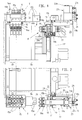
- die Kupplungseinrichtung an einer im Spannraum der Kunststoff-Spritzgießmaschine angeordneten Spritzgießform in Rückansicht und Draufsicht,
- Fig. 3, 4
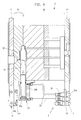
- Ausschnitte aus den Kupplungseinrichtungen gemäß Fign. 1 und 2 im Bereich der maschinenseitigen Gießformhälfte,
- Fig. 5
- einen Schnitt nach Linie 5-5 von Fig. 4 bei gelöster Kupplung,
- Fig. 6
- eine Darstellung gemäß Fig. 5,
- Fig. 7, 8
- Schnitte nach den Linien 7-7 und 8-8 der Fig. 3 und
- Fig. 9
- eine für das Ziehen von Kernen geeignete Spritzgießform mit ihren gießformseitigen Kupplungshälften in Draufsicht.
- 1, 2
- the coupling device on an injection mold arranged in the clamping space of the plastic injection molding machine in rear view and top view,
- 3, 4
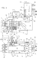
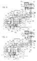
- Excerpts from the coupling devices according to FIGS. 1 and 2 in the area of the mold half on the machine side,
- Fig. 5
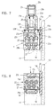
- 4 shows a section along line 5-5 of FIG. 4 with the clutch released,
- Fig. 6
- 5 shows a representation according to FIG.
- 7, 8
- Cuts along lines 7-7 and 8-8 of Fig. 3 and
- Fig. 9
- an injection mold suitable for drawing cores with its mold-side coupling halves in plan view.
Die Gießformhälften Sa und Sb der Spritzgießform S sind mittels Anlageplatten 11 auf die Formträger 13, 13' (Fig. 1, 2, 9) einer Formschließeinheit der Kunststoff-Spritzgießmaschine aufspannbar. Die Kupplungseinrichtung gewährleistet den Anschluß von Versorgungsleitungen an die Spritzgießform S bei deren Temperierung und beim Vollzug der operativen Gießformfunktionen, wie beispielsweise beim hydraulischen Ziehen von Kernen, dem Druckluftausstoß von Spritzteilen und der Abgabe von Signalen. An der bewegbaren Gießformhälte Sb bildet eine Kupplungshälfte 26, 28a mit einer maschinenseitigen Kupplungshälfte 27, 28b die bewegbare Kupplung F für Versorgungsleitungen für operative Funktionen der Spritzgießform. Die Kupplungshälfte 27, 28b umfaßt einen oberen hydraulischen Kupplungsteil 27 und einen unteren elektrischen Kupplungsteil 28b. An der stationären Gießformhälfte Sa bildet eine Kupplungshälfte 14 mit einer maschinenseitigen Kupplungshälfte 15 eine stationäre Kupplung T für Versorgungsleitungen für die Temperierung der Spritzgießform. Für die bewegbare Kupplung und die stationäre Kupplung ist je ein hydraulischer Antriebszylinder vorgesehen, durch dessen Antriebshub die maschinenseitigen Kupplungshälften 27, 28b; 15 an die gießformseitigen Kupplungshälften 26, 28a; 14 an- bzw. abkuppelbar sind. Somit ist die im Bereich der stationären Gießformhälfte Sa angeordnete Kupplung T für die Temperierung der Spritzgießform und die im Bereich der bewegbaren Gießformhälte Sb angeordneten Kupplung F für den Vollzug von operativen Gießformfunktionen wesentlich bestimmt und geeignet. Die Figuren 1 bis 8 zeigen die zuvor auf einem Wechseltisch temperierte und danach in den Spannraum der Spritzgießmaschine einfahrene Spritzgießform, bei welcher die stationäre Kupplung T bereits bei Beginn der Temperierung auf dem Wechseltisch geschlossen und beim Einfahren in den Spannraum in geschlossenem Zustand verblieben ist.The mold halves Sa and Sb of the injection mold S can be clamped by means of
Die Kupplungsrichtung der im Bereich der stationären Gießformhälfte Sa befestigten stationären Kupplung T verläuft parallel zur Trennebene t-t der spritzgießform S. Die Kupplungsrichtung der im Bereich der bewegbaren Gießformhälte Sb angeordneten bewegbaren Kupplung F verläuft senkrecht zur Trennebene t-t. Wie insbesondere aus den Fign. 2, 9 ersichtlich, überragen die Anlageplatten 11 den Gießformkörper der Spritzgießform S nach rückwärts. Die gießformseitigen Kupplungshälften 14, 26 sind je im Bereich der den Gießformkörper überragenden Abschnitte der Anlageplatten 11 angeordnet. Die eine gießformseitige Kupplungshälfte 14 ist an der Oberkante der Anlageplatte 11 der stationären Gießformhälfte Sa befestigt, die andere gießformseitige Kupplungshälfte 26 ist an einer am bewegbaren Formträger 13' befestigten Anschlußplatte 18 befestigt. Diese Anschlußplatte 18 ist, wie insbesondere aus Fig. 2 erkennbar, in einer entsprechenden Aussparung der Anlageplatte 11 teilweise eingebettet. Die Richtung des Antriebshubes der hydraulischen Antriebszylinder 23, 15a der Kupplungsenrichtung verläuft je senkrecht zur Kupplungsrichtung der angetriebenen Kupplungshälften. Der Kraftvektor des Antriebshubes wird mittels Steuerplatten 25 um 90° umgelenkt, die mit schrägen Steuernuten 25a versehen sind. Die Steuerplatten 25 sind mit der Kolbenstange 23e des Antriebszylinders 23 mittels einer Lagerachse 23h verbunden. Zur Umlenkung des Kraftvektors des Antriebshubes greifen Steuerzapfen 22b eines die zugehörigen Kupplungshälften 27, 28b tragenden Schlittens 22 in die schrägen Steuernuten 25a der Steuerplatten 25 ein. Der Schlitten 22 mit seinen Kupplungshälften 27, 28b bildet mit dem den Antriebszylinder 23 tragenden Trägerelement 19 eine bauliche Einheit. Diese Einheit ist in einer mit dem bewegbaren Formträger 13 mittels Schraubenbolzen 21 fest verbundenen vertikalen Lagerplatte 20 begrenzt horizontal verschiebbar gelagert. Sie kann durch Anschrauben der Lagerplatte 20 an den Formträger 13' der in Arbeitsposition befindlichen Spritzgießform S zum Einsatz gebracht werden.The coupling direction of the stationary coupling T fastened in the region of the stationary mold half Sa runs parallel to the parting plane tt of the injection mold S. The coupling direction of the movable coupling F arranged in the region of the movable mold half Sb runs perpendicular to the parting plane tt. As in particular from FIGS. 2, 9 can be seen, the
Die Fign. 1-5 zeigen die genannte Einheit vor ihrer Verspannung mit der Anschlußplatte 18 je bei noch nicht geschlossener Kupplung.The figures 1-5 show the unit mentioned before it is braced with the connecting
Wie insbesondere aus den Fign. 3-6 erkennbar, nimmt der Schlitten die Kupplungshälften 27, 28b mit einem plattenförmigen, der Gießform S zu gewandten vertikalen Trägerteil 22a auf. Von diesem Trägerteil 22a erstrecken sich zwei horizontale Schenkel 22c des Schlittens nach rückwärts. Der Schlitten 22 ist an Führungsrippen 19c des, den Antriebszylinder 23 abstützenden, Trägerelementes 19 horizontal geführt. Dabei ist der blockartig ausgebildete eigentliche. Zylinder 23f des Antriebszylinders 23 mittels Befestigungsschrauben 23g mit Lagersockeln 19d des Trägerelementes 19 verbunden (Fig. 3). Der Kolben 23d des Antriebszylinders 23 begrenzt Zylinderräume 23b, die über Hydraulikanschlüsse 23c mit Druckmedium beschickbar sind. Mit 23a ist ein den rückseitigen Zylinderraum abschließender Zylinderdeckel und mit 24 Endschalter zur Steuerung des Antriebszylinders 23 bezeichnet. Wie insbesondere aus Fig. 4 erkennbar, ist das langgestreckte Trägerelement 19 über seitliche Anformungen 19b mittels Schraubenbolzen an der Lagerplatte 20 abgestützt, welche Schraubenbolzen 29, wie weiter unten noch auszuführen ist, als Wegbegrenzungselemente dienen. Der Antriebshub des im Bereich des bewegbaren Formträgers 13 angeordneten Antriebszylinders 23 ist in einen Kupplungsweg für die Ankupplung der maschinenseitigen Kupplungshälfte 27, 28b und einen Spannweg für die Verspannung des den Antriebszylinder tragenden Trägerelementes 19 mit der bewegbaren Gießformhälfte Sb umsetzbar. Der Kupplungsweg ist mittels einer Wegbegrenzungsnut 20a in der Lagerplatte 20 begrenzt. In die Wegbegrenzungsnut 20a taucht der die Steuernut 25a der benachbarten Steuerplatte 25 durchgreifende Steuerzapfen 22b des Schlittens 22 ein. Der Spannweg ist mittels einer Wegbegrenzungsausnehmungen 20b (Fig. 4) in der Lagerplatte 20 begrenzt. In die Begrenzungsausnehmungen 20b tauchen Wegbegrenzungselemente 29 des Trägerelementes 19 mit einem dem Spannweg entsprechenden Spiel, ein wie insbesondere aus Fig. 4 ersichtlich.As in particular from FIGS. 3-6 recognizable, the carriage receives the coupling halves 27, 28b with a plate-shaped vertical support part 22a facing the casting mold S. Two
Im letzten Abschnitt des Kupplungsweges kuppeln die Kupplungsorgane 27a, 28b' (Fig. 3) der angetriebenen maschinenseitigen Kupplungshälften 27, 28b mit den Kupplungsorganen 26a, 28a' (Fig. 3,5) der gießformseitigen Kupplungshälften 26, 28a.In the last section of the coupling path, the
Beim Antriebshub des Antriebszylinders 23 gelangt der Schlitten 22 mit seiner Kupplungshälfte 27, 28b sowie das Trägerelement 19 mit seiner Hintergriffsnase 19a aus einer Stellung gemäß Fig. 5 in eine Position gemäß Fig. 6. Dabei bewegt sich das Trägerelement 19 nach Maßgabe des Spiels in der Wegbegrenzungsausnehmung 20b geringfügig nach rechts, wobei sich die Hintergriffsnase 19a an die Stirnseite der Anschlußplatte 18 anlegt. Andererseits bewegt sich der Schlitten 22 nach Maßgabe der Länge der Wegbegrenzungsnut 20a (Fig. 4) nach links bis der Steuerzapfen 22b an die linke Kante der Wegbegrenzungsnut 20a anschlägt. Der entgegengesetzte Antrieb von Trägerelement 19 und Schlitten 22 resultiert daraus, daß die Steuernut 25a im Gefolge einer Vertikalbewegung eine horizontale Antriebsbewegung des Schlittens nach links und eine Bewegung des Trägerelements 19 nach rechts erzwingt. Diese Horizontalbewegungen realisieren den Kupplungsweg und den Spannweg.During the drive stroke of the
Da der Hydraulikzylinder 23 fest auf dem Trägerelement 19 aufsitzt, also gewissermaßen am Trägerelement 19 widergelagert ist, wird beim Antriebshub des Hydraulikzylinders 23 nach Maßgabe des Spiels in der Wegbegrenzungsausnehmung 20b auch die Horizontalbewegung des Trägerelements 19 erzwungen. Zur Schonung der unteren elektrischen Kupplungsteile 28a, 28b der bewegbaren Kupplung F ist das maschinenseitige Kupplungsteil 28b rückseitig mittels Schraubenfedern gepuffert.Since the
Bei einer solchen Ausbildung der Kupplungseinrichtung ist die aus der maschinenseitigen Kupplungshälfte 27; 28b und deren Träger (Schlitten 22) sowie dem zugehörigen hydraulischen Antriebszylinder 23 und dessen Träger (Trägerelement 19) bestehende und mittels der Anschlußplatte 18 am bewegbaren Formträger 13' begrenzt verschieblich abgestützte bauliche Einheit nach Vollzug der Kupplung mit der Anlageplatte 11 der Spritzgießform fest verspannt. Dabei greift die Nase 19a des Trägerelementes 19 auf der einen Seite der Anlageplatte 11 und das Trägerteil 22a für die Kupplungshälfte 27;28b des Schlittens 22 auf der anderen Seite der Anlageplatte 11 an. Die genannte Spann- und Kupplungsoperation setzt also voraus, daß der Antriebshub des hydraulischen Antriebszylinders 23 in eine entgegengesetzte Bewegung von Trägerelement 19 und Schlitten 22 umgesetzt wird. Je nach Ausgangslage kann dabei die Spannbewegung des Trägerelementes 19 relativ gering und die Spannbewegung des Schlittens 20 entsprechend groß - oder umgekehrt sein. Die genannten Spannbewegungen können je nach auftretenden Friktionen gleichzeitig oder nacheinander erfolgen.With such a configuration of the coupling device, the
Fig. 9 verdeutlicht die Versorgung eines einen metallenen Kern 31 steuernden Hydraulikzylinders 30 über die gießformseitige Kupplungshälfte 26 und Verbindungsleitungen 33 mit Druckmedium. Die Achse des Hydraulikzylinders 30 mit Kolbenstange 30a und eigentlichem Zylinder 30b liegt in der Trennebene t-t und verläuft horizontal. Der Kern 31 ist bereits aus dem fertigen Spritzteil 32 herausgezogen.9 illustrates the supply of a
In den Fign. 1 und 2 sind mit 15e die maschinenseitigen Anschlüsse der Versorgungsleitungen an der Kupplung T und mit 14a die gießformseitigen Anschlüsse der Versorgungsleitungen an die gießformseitige Kupplungshälfte 14 bezeichnet. Beim Kupplungshub ist die maschinenseitige Kupplungshälfte 15 an den Führungsbolzen 34 vertikal geführt. Diese sind oben mittels Hintergriffsorganen 34a an einer. Brücke des Wechseltisches und mit unteren Hintergriffsorganen 34b an der gießformseitigen Kupplungshälfte 14 abstützbar, wo sie in eine Führungsnut 16 der Kupplungshälfte 14 eingreifen. Die Umlenkung des Kraftvektors des Antriebshubes des Antriebszylinders 15a für die stationäre Kupplung T wird durch analoge technische Mittel bewirkt wie beim Antriebszylinder 23 für die bewegbare Kupplung F.In Figs. 1 and 2, 15e denotes the machine-side connections of the supply lines to the coupling T and 14a the mold-side connections of the supply lines to the casting-mold
Claims (9)
- Coupling assembly on the injection mould (S), which is provided with back plates (11), of a plastics material injection moulding machine, which is intended and suitable both for the supply of temperature control media and for the execution of operative mould functions, such as, for example, the hydraulic pulling of cores, the ejection of compressed air from mouldings, the transmission of signals, and the like,
including a coupling half (26, 28a), which is secured to the movable mould half (Sb) and forms with a machine-side coupling half (27, 28b) a movable coupling (F) for the connection of supply lines, and including a coupling half (14), which is secured to the stationary mould half (Sa) and forms with a machine-side coupling half (15) a stationary coupling (T) for the connection of supply lines,
and including hydraulic actuating cylinders (23; 15a), by means of which the two above-mentioned couplings (F; T) are couplable as a consequence of an actuating stroke according to the program of the computer of the plastics material injection moulding machine, the back plates (11) of the injection mould (S) protruding from the mould body, and each of the mould-side coupling halves (14; 26) being securable in the region of the protruding portions of the back plates (11),
characterised in that the movable coupling (F) is provided for the coupling and uncoupling of supply lines for the execution of operative mould functions, and the stationary coupling (T) is provided for the coupling and uncoupling of the supply lines for the temperature control medium for the temperature control of both mould halves (Sa; Sb); the coupling direction of the movable coupling (F) extends at right angles to the parting plane (t-t) of the injection mould (S); and the actuating stroke of the actuating cylinder (23) is convertible into a coupling movement for the coupling of the machine-side coupling half (27) and into a clamping movement in the opposite direction for the clamping of the carrier (19) of the actuating cylinder (23) to the movable mould half (Sb). - Coupling assembly according to claim 1, characterised in that the coupling direction of the stationary coupling (T) extends parallel to the parting plane (t-t) of the injection mould (S).
- Coupling assembly according to claim 1 or 2, characterised in that one mould-side coupling half (14) is securable to the top edge of the back plate (11) of the stationary mould half (Sa), and the other mould-side coupling half (26) is securable to a mounting plate (18) fastened to the back plate (11) of the movable mould half (Sb).
- Coupling assembly according to one of the preceding claims, characterised in that the direction of each actuating stroke of the hydraulic actuating cylinder (23; 15a) extends at right angles to the coupling direction of the couplings (F; T), which are actuated by said actuating cylinders (23; 15a), and the force vector of the actuating stroke is deflectable through 90° by means of cam plates (25), which are provided with oblique cam slots (25a).
- Coupling assembly according to claim 4, characterised in that, in order to deflect the force vector of the actuating stroke of the actuating cylinder (23), which is disposed on the movable mould carrier (13'), cam follower pins (22b) of a carriage (22) carrying the associated coupling half (27) engage in the oblique cam slots (25a) in the cam plates (25) of this actuating cylinder (23).
- Coupling assembly according to claim 5, characterised in that the carriage (22) is guided on a carrier (19), which supports the actuating cylinder (23) and is clampable to the movable mould half (Sb) by means of a locking nose (19a), which abuts against a mounting plate (18) of the mould half (Sb) in the clamping position.
- Coupling assembly according to claim 6, characterised in that the coupling movement is limited by means of a limiting groove (20a) in a bearing plate (20), which is secured to the movable mould carrier (13') and in which the cam follower pin (22b) of the carriage (22) extends, said pin traversing the cam slot (25a) in the adjacent cam plate (25), and in that the clamping movement is limited by means of a limiting recess (20b in Fig. 4) in the bearing plate (20), a limiting means (29) of the carriage (22) extnding into said limiting recess (20b) with a clearance corresponding to the clamping movement.
- Coupling assembly according to one of the preceding claims, characterised in that, during the actuating stroke of the associated actuating cylinder (15a), the machine-side coupling half (15) of the stationary coupling (T) is guided on guide pins (34 in Fig. 1), which are supported on a changing table externally of the plastics material injection moulding machine.
- Coupling assembly according to one of claims 5 to 8, characterised in that the carriage (22), which carries an hydraulic coupling part (27 in Figs. 3 and 6) and an electrical coupling part (28b), forms with the carrier (19) carrying the actuating cylinder (23) a structural unit which is mounted in a vertical bearing plate (20), screw-connected to the movable mould carrier (13) by means of screws (21), so as to be horizontally displaceable to a limited extent.
Applications Claiming Priority (2)
| Application Number | Priority Date | Filing Date | Title |
|---|---|---|---|
| DE4029431A DE4029431A1 (en) | 1990-09-17 | 1990-09-17 | CLUTCH DEVICE ON THE INJECTION MOLD OF A PLASTIC INJECTION MOLDING MACHINE |
| DE4029431 | 1990-09-17 |
Publications (2)
| Publication Number | Publication Date |
|---|---|
| EP0476236A1 EP0476236A1 (en) | 1992-03-25 |
| EP0476236B1 true EP0476236B1 (en) | 1995-02-22 |
Family
ID=6414403
Family Applications (1)
| Application Number | Title | Priority Date | Filing Date |
|---|---|---|---|
| EP91110005A Expired - Lifetime EP0476236B1 (en) | 1990-09-17 | 1991-06-19 | Clutch device on the mould of a plastics injection moulding machine |
Country Status (7)
| Country | Link |
|---|---|
| US (1) | US5234337A (en) |
| EP (1) | EP0476236B1 (en) |
| JP (1) | JP2572689B2 (en) |
| AT (1) | ATE118720T1 (en) |
| CA (1) | CA2051309A1 (en) |
| DE (2) | DE4029431A1 (en) |
| ES (1) | ES2069776T3 (en) |
Families Citing this family (7)
| Publication number | Priority date | Publication date | Assignee | Title |
|---|---|---|---|---|
| IT1240949B (en) * | 1990-06-12 | 1993-12-27 | Bazzica Engineering Di Carlo Bazzica & C. S.A.S. | METHOD AND MACHINE FOR THE PRODUCTION OF EXPANDED POLYSTYRENE PIECES. |
| US20040169320A1 (en) * | 2003-02-28 | 2004-09-02 | Petrucci Alan A. | Plastic injection mold assembly and method of molding threaded plastic parts |
| US7828541B2 (en) * | 2007-05-22 | 2010-11-09 | Coeur, Inc. | Motor driven mold |
| AT511644A1 (en) * | 2011-07-11 | 2013-01-15 | Ifw Manfred Otte Gmbh | FORM TOOL WITH ADJUSTABLE FORM core |
| FR2990640B1 (en) * | 2012-05-21 | 2014-06-13 | Sidel Participations | "DEVICE FOR MANUFACTURING CONTAINERS COMPRISING A MOLD AND A FLUID CONNECTION PLUG PROVIDED WITH MECHANISMS FOR TIGHTENING THE MOLD" |
| US9339957B2 (en) * | 2014-05-07 | 2016-05-17 | Athena Automation Ltd. | Stack mold support structure for an injection molding machine |
| DE102016205554B4 (en) * | 2016-04-04 | 2022-02-24 | Rekers Gmbh Maschinen- Und Anlagenbau | Mandrel device for a block molding machine, block molding machine and method for producing shaped blocks |
Family Cites Families (10)
| Publication number | Priority date | Publication date | Assignee | Title |
|---|---|---|---|---|
| DE1147750B (en) * | 1959-06-06 | 1963-04-25 | Krauss Maffei Ag | Mold closing device, especially for injection molding machines that process thermoplastics |
| FR1516120A (en) * | 1967-01-24 | 1968-03-08 | Die-casting machine mold closing device | |
| US4158910A (en) * | 1977-06-16 | 1979-06-26 | Honeywell Inc. | Injection molding method and apparatus for accommodating various sizes of molding die inserts |
| JPS63416Y2 (en) * | 1980-03-27 | 1988-01-07 | ||
| JPS643569Y2 (en) * | 1980-08-28 | 1989-01-31 | ||
| US4487287A (en) * | 1981-08-03 | 1984-12-11 | Mazda Motor Corporation | Support system for automobile power plant |
| DE3222828C2 (en) * | 1982-06-18 | 1984-04-12 | Karl 7298 Loßburg Hehl | Mold closing unit with waiting stations for heating injection molds and with a mold changing device |
| DE3509518C1 (en) * | 1985-03-16 | 1986-09-18 | Karl 7298 Loßburg Hehl | Mold closing unit with a mold changing device and an adaptation table for preheating plastic injection molds |
| DD259957A3 (en) * | 1986-06-30 | 1988-09-14 | Schwerin Plastmaschinen | DEVICE FOR VERTICALLY CHANGING AND TENANTS OF MOLDING TOOLS |
| JPS63222831A (en) * | 1987-03-13 | 1988-09-16 | Fanuc Ltd | Motor driven mold clamping mechanism |
-
1990
- 1990-09-17 DE DE4029431A patent/DE4029431A1/en active Granted
-
1991
- 1991-06-19 EP EP91110005A patent/EP0476236B1/en not_active Expired - Lifetime
- 1991-06-19 DE DE59104672T patent/DE59104672D1/en not_active Expired - Fee Related
- 1991-06-19 AT AT91110005T patent/ATE118720T1/en not_active IP Right Cessation
- 1991-06-19 ES ES91110005T patent/ES2069776T3/en not_active Expired - Lifetime
- 1991-09-13 US US07/759,160 patent/US5234337A/en not_active Expired - Fee Related
- 1991-09-13 CA CA002051309A patent/CA2051309A1/en not_active Abandoned
- 1991-09-17 JP JP3265362A patent/JP2572689B2/en not_active Expired - Lifetime
Also Published As
| Publication number | Publication date |
|---|---|
| DE4029431A1 (en) | 1992-03-26 |
| ATE118720T1 (en) | 1995-03-15 |
| US5234337A (en) | 1993-08-10 |
| ES2069776T3 (en) | 1995-05-16 |
| CA2051309A1 (en) | 1992-03-18 |
| EP0476236A1 (en) | 1992-03-25 |
| DE59104672D1 (en) | 1995-03-30 |
| JP2572689B2 (en) | 1997-01-16 |
| JPH04364915A (en) | 1992-12-17 |
| DE4029431C2 (en) | 1993-01-14 |
Similar Documents
| Publication | Publication Date | Title |
|---|---|---|
| EP1673208B1 (en) | Horizontal injection molding machine comprising a turning device | |
| DE3222828C2 (en) | Mold closing unit with waiting stations for heating injection molds and with a mold changing device | |
| EP0424624B1 (en) | Injection mould for pieces injected from plastifiable material, in particular from plastifiable liquid crystal polymers | |
| AT503968B1 (en) | injection molding | |
| DE19851043A1 (en) | Side sprue die-casting device with movable distributor | |
| CH455263A (en) | Machine for forming carrier containers for bottles | |
| WO2008040437A1 (en) | Plastics injection mould | |
| EP0824057A1 (en) | Method and apparatus for manufacturing plastic injection moulded articles | |
| EP0476236B1 (en) | Clutch device on the mould of a plastics injection moulding machine | |
| DE10110611C2 (en) | Device for injection molding molded articles made of plastic | |
| EP1973722B1 (en) | Operating device for shut-off needles in injection-moulding devices with needle valve nozzles | |
| EP0720525B1 (en) | Double closing unit for an injection moulding machine | |
| DE69723722T2 (en) | CLAMP FOR QUICK LOCKING | |
| EP2625019B1 (en) | Injection molding machine | |
| CH625461A5 (en) | Injection moulding machine with multi-daylight mould for plasticatable compositions | |
| EP0576837B1 (en) | Injection mouding machine with stack mould | |
| DE102013216008A1 (en) | Injection molding machine for several injection molding operations | |
| EP2134528B1 (en) | Moulding tool with a modular construction comprising a frame | |
| EP0605025A1 (en) | Injection moulding or injection-compression moulding machine | |
| EP0620095B1 (en) | Injection moulding machine | |
| DE102020106314B4 (en) | injection molding machine | |
| EP1848577B1 (en) | Injection moulding machine for processing plastic materials | |
| EP1480808B1 (en) | Closing device in a plastic injection molding machine | |
| DE4418452A1 (en) | Metal casting mould and metal mould casting apparatus | |
| DE2824729A1 (en) | Injection mould esp. for multiple small mouldings - has heated inlet block with heat regenerator near surfaces which cool during contact with mould |
Legal Events
| Date | Code | Title | Description |
|---|---|---|---|
| PUAI | Public reference made under article 153(3) epc to a published international application that has entered the european phase |
Free format text: ORIGINAL CODE: 0009012 |
|
| AK | Designated contracting states |
Kind code of ref document: A1 Designated state(s): AT CH DE ES FR GB IT LI NL |
|
| 17P | Request for examination filed |
Effective date: 19920131 |
|
| 17Q | First examination report despatched |
Effective date: 19931001 |
|
| GRAA | (expected) grant |
Free format text: ORIGINAL CODE: 0009210 |
|
| AK | Designated contracting states |
Kind code of ref document: B1 Designated state(s): AT CH DE ES FR GB IT LI NL |
|
| REF | Corresponds to: |
Ref document number: 118720 Country of ref document: AT Date of ref document: 19950315 Kind code of ref document: T |
|
| REF | Corresponds to: |
Ref document number: 59104672 Country of ref document: DE Date of ref document: 19950330 |
|
| GBT | Gb: translation of ep patent filed (gb section 77(6)(a)/1977) |
Effective date: 19950322 |
|
| ET | Fr: translation filed | ||
| ITF | It: translation for a ep patent filed |
Owner name: CALVANI SALVI E VERONELLI S.R.L. |
|
| REG | Reference to a national code |
Ref country code: ES Ref legal event code: FG2A Ref document number: 2069776 Country of ref document: ES Kind code of ref document: T3 |
|
| PLBE | No opposition filed within time limit |
Free format text: ORIGINAL CODE: 0009261 |
|
| STAA | Information on the status of an ep patent application or granted ep patent |
Free format text: STATUS: NO OPPOSITION FILED WITHIN TIME LIMIT |
|
| 26N | No opposition filed | ||
| PGFP | Annual fee paid to national office [announced via postgrant information from national office to epo] |
Ref country code: NL Payment date: 19970630 Year of fee payment: 7 Ref country code: ES Payment date: 19970630 Year of fee payment: 7 |
|
| PGFP | Annual fee paid to national office [announced via postgrant information from national office to epo] |
Ref country code: GB Payment date: 19980608 Year of fee payment: 8 |
|
| PGFP | Annual fee paid to national office [announced via postgrant information from national office to epo] |
Ref country code: FR Payment date: 19980617 Year of fee payment: 8 |
|
| PG25 | Lapsed in a contracting state [announced via postgrant information from national office to epo] |
Ref country code: ES Free format text: LAPSE BECAUSE OF EXPIRATION OF PROTECTION Effective date: 19980620 |
|
| PGFP | Annual fee paid to national office [announced via postgrant information from national office to epo] |
Ref country code: AT Payment date: 19980623 Year of fee payment: 8 |
|
| PGFP | Annual fee paid to national office [announced via postgrant information from national office to epo] |
Ref country code: CH Payment date: 19980701 Year of fee payment: 8 |
|
| PG25 | Lapsed in a contracting state [announced via postgrant information from national office to epo] |
Ref country code: NL Free format text: LAPSE BECAUSE OF NON-PAYMENT OF DUE FEES Effective date: 19990101 |
|
| NLV4 | Nl: lapsed or anulled due to non-payment of the annual fee |
Effective date: 19990101 |
|
| PG25 | Lapsed in a contracting state [announced via postgrant information from national office to epo] |
Ref country code: GB Free format text: LAPSE BECAUSE OF NON-PAYMENT OF DUE FEES Effective date: 19990619 Ref country code: AT Free format text: LAPSE BECAUSE OF NON-PAYMENT OF DUE FEES Effective date: 19990619 |
|
| PG25 | Lapsed in a contracting state [announced via postgrant information from national office to epo] |
Ref country code: LI Free format text: LAPSE BECAUSE OF NON-PAYMENT OF DUE FEES Effective date: 19990630 Ref country code: FR Free format text: THE PATENT HAS BEEN ANNULLED BY A DECISION OF A NATIONAL AUTHORITY Effective date: 19990630 Ref country code: CH Free format text: LAPSE BECAUSE OF NON-PAYMENT OF DUE FEES Effective date: 19990630 |
|
| GBPC | Gb: european patent ceased through non-payment of renewal fee |
Effective date: 19990619 |
|
| REG | Reference to a national code |
Ref country code: CH Ref legal event code: PL |
|
| REG | Reference to a national code |
Ref country code: ES Ref legal event code: FD2A Effective date: 20000301 |
|
| REG | Reference to a national code |
Ref country code: FR Ref legal event code: ST |
|
| PGFP | Annual fee paid to national office [announced via postgrant information from national office to epo] |
Ref country code: DE Payment date: 20010410 Year of fee payment: 11 |
|
| PG25 | Lapsed in a contracting state [announced via postgrant information from national office to epo] |
Ref country code: DE Free format text: LAPSE BECAUSE OF NON-PAYMENT OF DUE FEES Effective date: 20030101 |
|
| PG25 | Lapsed in a contracting state [announced via postgrant information from national office to epo] |
Ref country code: IT Free format text: LAPSE BECAUSE OF NON-PAYMENT OF DUE FEES;WARNING: LAPSES OF ITALIAN PATENTS WITH EFFECTIVE DATE BEFORE 2007 MAY HAVE OCCURRED AT ANY TIME BEFORE 2007. THE CORRECT EFFECTIVE DATE MAY BE DIFFERENT FROM THE ONE RECORDED. Effective date: 20050619 |