EP0620095B1 - Injection moulding machine - Google Patents
Injection moulding machine Download PDFInfo
- Publication number
- EP0620095B1 EP0620095B1 EP93115689A EP93115689A EP0620095B1 EP 0620095 B1 EP0620095 B1 EP 0620095B1 EP 93115689 A EP93115689 A EP 93115689A EP 93115689 A EP93115689 A EP 93115689A EP 0620095 B1 EP0620095 B1 EP 0620095B1
- Authority
- EP
- European Patent Office
- Prior art keywords
- mould carrier
- supporting element
- injection moulding
- movable
- stationary
- Prior art date
- Legal status (The legal status is an assumption and is not a legal conclusion. Google has not performed a legal analysis and makes no representation as to the accuracy of the status listed.)
- Expired - Lifetime
Links
Images


Classifications
-
- B—PERFORMING OPERATIONS; TRANSPORTING
- B30—PRESSES
- B30B—PRESSES IN GENERAL
- B30B15/00—Details of, or accessories for, presses; Auxiliary measures in connection with pressing
- B30B15/04—Frames; Guides
- B30B15/044—Means preventing deflection of the frame, especially for C-frames
-
- B—PERFORMING OPERATIONS; TRANSPORTING
- B29—WORKING OF PLASTICS; WORKING OF SUBSTANCES IN A PLASTIC STATE IN GENERAL
- B29C—SHAPING OR JOINING OF PLASTICS; SHAPING OF MATERIAL IN A PLASTIC STATE, NOT OTHERWISE PROVIDED FOR; AFTER-TREATMENT OF THE SHAPED PRODUCTS, e.g. REPAIRING
- B29C45/00—Injection moulding, i.e. forcing the required volume of moulding material through a nozzle into a closed mould; Apparatus therefor
- B29C45/17—Component parts, details or accessories; Auxiliary operations
- B29C45/1751—Adjustment means allowing the use of moulds of different thicknesses
-
- B—PERFORMING OPERATIONS; TRANSPORTING
- B29—WORKING OF PLASTICS; WORKING OF SUBSTANCES IN A PLASTIC STATE IN GENERAL
- B29C—SHAPING OR JOINING OF PLASTICS; SHAPING OF MATERIAL IN A PLASTIC STATE, NOT OTHERWISE PROVIDED FOR; AFTER-TREATMENT OF THE SHAPED PRODUCTS, e.g. REPAIRING
- B29C45/00—Injection moulding, i.e. forcing the required volume of moulding material through a nozzle into a closed mould; Apparatus therefor
- B29C45/17—Component parts, details or accessories; Auxiliary operations
- B29C45/1761—Means for guiding movable mould supports or injection units on the machine base or frame; Machine bases or frames
-
- B—PERFORMING OPERATIONS; TRANSPORTING
- B29—WORKING OF PLASTICS; WORKING OF SUBSTANCES IN A PLASTIC STATE IN GENERAL
- B29C—SHAPING OR JOINING OF PLASTICS; SHAPING OF MATERIAL IN A PLASTIC STATE, NOT OTHERWISE PROVIDED FOR; AFTER-TREATMENT OF THE SHAPED PRODUCTS, e.g. REPAIRING
- B29C45/00—Injection moulding, i.e. forcing the required volume of moulding material through a nozzle into a closed mould; Apparatus therefor
- B29C45/17—Component parts, details or accessories; Auxiliary operations
- B29C45/64—Mould opening, closing or clamping devices
- B29C45/66—Mould opening, closing or clamping devices mechanical
- B29C45/661—Mould opening, closing or clamping devices mechanical using a toggle mechanism for mould clamping
-
- B—PERFORMING OPERATIONS; TRANSPORTING
- B29—WORKING OF PLASTICS; WORKING OF SUBSTANCES IN A PLASTIC STATE IN GENERAL
- B29C—SHAPING OR JOINING OF PLASTICS; SHAPING OF MATERIAL IN A PLASTIC STATE, NOT OTHERWISE PROVIDED FOR; AFTER-TREATMENT OF THE SHAPED PRODUCTS, e.g. REPAIRING
- B29C45/00—Injection moulding, i.e. forcing the required volume of moulding material through a nozzle into a closed mould; Apparatus therefor
- B29C45/17—Component parts, details or accessories; Auxiliary operations
- B29C45/1761—Means for guiding movable mould supports or injection units on the machine base or frame; Machine bases or frames
- B29C2045/1763—Means for guiding movable mould supports or injection units on the machine base or frame; Machine bases or frames preventing distortion of the machine part guiding the movable mould
-
- B—PERFORMING OPERATIONS; TRANSPORTING
- B29—WORKING OF PLASTICS; WORKING OF SUBSTANCES IN A PLASTIC STATE IN GENERAL
- B29C—SHAPING OR JOINING OF PLASTICS; SHAPING OF MATERIAL IN A PLASTIC STATE, NOT OTHERWISE PROVIDED FOR; AFTER-TREATMENT OF THE SHAPED PRODUCTS, e.g. REPAIRING
- B29C45/00—Injection moulding, i.e. forcing the required volume of moulding material through a nozzle into a closed mould; Apparatus therefor
- B29C45/17—Component parts, details or accessories; Auxiliary operations
- B29C45/1761—Means for guiding movable mould supports or injection units on the machine base or frame; Machine bases or frames
- B29C2045/1768—Means for guiding movable mould supports or injection units on the machine base or frame; Machine bases or frames constructions of C-shaped frame elements
-
- B—PERFORMING OPERATIONS; TRANSPORTING
- B29—WORKING OF PLASTICS; WORKING OF SUBSTANCES IN A PLASTIC STATE IN GENERAL
- B29C—SHAPING OR JOINING OF PLASTICS; SHAPING OF MATERIAL IN A PLASTIC STATE, NOT OTHERWISE PROVIDED FOR; AFTER-TREATMENT OF THE SHAPED PRODUCTS, e.g. REPAIRING
- B29C45/00—Injection moulding, i.e. forcing the required volume of moulding material through a nozzle into a closed mould; Apparatus therefor
- B29C45/17—Component parts, details or accessories; Auxiliary operations
- B29C2045/1784—Component parts, details or accessories not otherwise provided for; Auxiliary operations not otherwise provided for
- B29C2045/1792—Machine parts driven by an electric motor, e.g. electric servomotor
- B29C2045/1794—Machine parts driven by an electric motor, e.g. electric servomotor by a rotor or directly coupled electric motor, e.g. using a tubular shaft motor
Definitions
- the invention relates to an injection molding machine according to the preamble of claim 1.
- Such an injection molding machine is for example from DE-U 92 12 480 known.
- This injection molding machine has support elements and mold carrier plate articulated and tiltable with a cast iron Machine foot connected, which occurs during the closing Closing force and the one that occurs during injection Buoyancy force between the support element and the platen derives.
- guides are provided for the movable mold carrier, around this especially with eccentric loads, for example due to eccentric mold cavities parallel to the other mold half to lead. The principle is followed, the machine base so stiff to train that he is minimal under the emerging forces deformed and the remaining deformations by the articulated storage of the mold carrier plate and support element from the Keep shape out.
- EP-A 504 580 is a pressing device for a flash butt welding machine known in which a separate power transmission element is provided, which is articulated at both ends of a press is. To release the power transmission element, this is with locking rings held at both ends without taking any precautions are able to replace separate joint parts for themselves.
- the press parts themselves are stationary on the one hand with the machine base connected and supported on the other hand via a support element, the moves when applying the pressing force so that a point of articulation on a radius opposite the connection point with the machine base is moved. This leads to a vertical component in the Forces and thus to an undesired deflection that the Precision of the device is negatively affected.
- a support element and a mold carrier plate articulated to a cast iron machine base, which during closing and during injection forces that occur.
- a toggle mechanism at which the drive device at the articulation points of the toggle lever is freely suspended, the movable mold carrier and a support element for the toggle jointed together, whereby Evasive movements of the movable mold carrier can be avoided.
- the Machine base is designed according to DE-U 92 12 480.
- a deformation element provided that can deform without substantially from the Tensions in the machine base caused by movement and spraying forces be derived.
- the deformation element forms with the other parts of the mold clamping unit a closed power frame and can be optimally adapted to the respective operating conditions become.
- the deformations have almost no influence on the position of the fixed platen. Peripherals screwed to the machine base, how handling and removal devices become from the deformations not affected, so that an exact control of storage points is reproducibly possible.
- the horizontal nozzle zero remains at zero even with maximum locking force, because the nozzle zero point due to the rigid connection between the fixed Platen and the machine base is fixed.
- the object of the invention based on an injection molding machine of the type mentioned to further develop such that those occurring on the mold clamping unit Deformation even after a long service life has no effect on the Machine base are derived without affecting the parallelism of shape.
- the deformations are no longer just outside the Main components of the mold clamping unit are derived and recorded, which creates a positive connection under pressure the parts that create a secure build of the clamping force guaranteed, but by the releasable attachment of the joint parts and the arrangement of the joints makes the shape parallelism easy adjust and readjust.
- the bending stress of the mold carrier is reduced, which is less Dimensioning of the mold carriers allowed and thus to reduce the overall height contributes.
- the detachable attachment the joints also create the structural conditions for easy changeability of the mold clamping dimensions.
- a nozzle zero is fixed. On spars can be dispensed with.
- a toggle mechanism is provided, the Joints at the same time as joints for articulating the force transmission element to serve.
- the toggle mechanism is a so-called "Y toggle lever", so that there is an extremely space-saving design of the mold clamping unit results, albeit for this drive device manageable space must be provided.
- An embodiment according to claim 6 has the advantage that a ball screw without special space inside the Hollow shaft motor can be performed.
- the Hollow shaft motor an additional transmission gear, so that the Space requirement in the machine base, which accommodates the drive device, is further minimized.
- the bracket becomes shorter and therefore lighter.
- the Use of the deformation element bracket has the advantage that in "Slipstream" of the bracket guides can be provided so that the guides in the mold clamping space in a room can be arranged by the bracket for a anyway Casting mold is only partially accessible.
- a free deformable deformation element When using a free deformable deformation element must the entire mold clamping unit supported reliably and axially movable at a second point become. With a toggle mechanism, this is not necessarily one Support element required, since only an articulated connection with the deformation element is necessary.
- the second bearing point that is axially movable relative to the machine base the mold clamping unit chosen so that it in the area of Articulation point of the toggle mechanism on that of the movable
- the side facing away from the mold carrier is arranged. The linkage takes place without disturbing the functioning of the bracket on the bracket itself, preferably in the area of the neutral fiber.
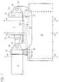
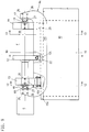
- All of the exemplary embodiments have in common that on a machine base 10 or a part thereof such as a swing frame 29 a stationary mold carrier 11 and a movable mold carrier 12 are arranged are.
- a Locking mechanism S provided on a support element 13 is arranged.
- the support element 13 is stationary Mold carrier movable over at least one power transmission element connected, which essentially with the closed mold 31st occurring closing and injection forces absorbs.
- the mobile Mold carrier 11 moves along a path of movement, preferably on guides 15, 22.
- the mold carriers have one between them Mold clamping space F for a casting mold 31 in FIG. 17. Both on stationary mold carrier 11 and on the movable mold carrier 12 Parts of the mold 31 can be determined.
- the power transmission element not only transmits the forces, but is a separate, deformable by the forces, Deformation element and in the exemplary embodiments as a bracket 14 educated.
- the bracket shape allows easy access to the Mold clamping space, but other shapes are also possible.
- the stationary Mold carrier 11 is on fasteners 23 on the machine base attached.
- all other parts of the Mold closing unit in particular movable mold carrier and Support element movable in relation to the machine base.
- the support element only on the rail 22 or the guide rail 15 is movably clawed and opposite Machine foot is movable along the closing direction. Become forces applied, so they have no influence on the machine base, because essentially only after derivation of the other deformations to an axial movement independent of the machine base in Closing direction comes.
- Deformation element 14 a decoupling of the deformations from the in Axial forces acting in the closing direction is possible. That’s it Deformation element freely suspended and with the support element 13 and the stationary mold carrier 11 articulated.
- the deformation element is formed by two C-shaped bracket 14, whereby the Injection opening E is kept clear.
- the linkage of the bracket on stationary mold carrier and the support element 13 is carried out Bearing elements.
- the bolt 17 is in a recess in the projection 11c stored, which passes through an eye 14d of the bracket 14.
- On the other Side is the bracket 14 via bolt 16 with the molding 13c as Support element trained cylinder plate connected, the Articulation point between the cylinder plate and the movable mold carrier 12 lies.
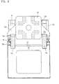
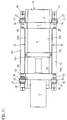
- FIGS. 9-15a In the third exemplary embodiment (FIGS. 9-15a), bolts 17 and 18 provided that as parts of a bearing by screws 25 on stationary mold carrier 11 or attached to the support member 13 are (Figs. 15, 16). The bolts are supported by a slide bearing 28 a bearing block 27 in connection with screws 26 on the bracket 14 is attached. This allows the forces to be released without torque transfer.
- bolts 17 and 18 are arranged that they are form-fitting between the stationary mold carrier 11 and bracket 14 or support member 13 and bracket 14 are added.
- the point of articulation in the area of the support element 13 is on the movable mold carrier 12 facing away from the support element arranged.
- Fig. 16 it can be seen that the bolts 17, 18 in Recesses 11a, 13a, 14a of the bracket 14, the stationary mold carrier 11 and the support element 13 are mounted. You will be perpendicular to passed through their axis by further bearing bolts 19 which in Bores 11b, 13b, 14b of bracket 14, stationary mold carrier 11 or Immerse the support element 13.
- the Bearing bolts 19 against the force of springs 20 in the bores 11b, 13b of stationary mold carrier and support element 13.
- This arrangement supports overcoming the demolding forces, but also leads to Frictional forces that make it difficult to decouple from the deformations.
- the Different arrangement options of the bracket create one Adaptability unmatched from the state of the art Customer requests e.g. with regard to different tool installation dimensions, if the bracket is articulated in front of or behind the support element.
- the Joint parts bolts 16, 17, 18 and bearing block 27 of the joints are through Screws on the articulated parts of the Closing unit releasably attached. If necessary, longer ones Screws 25 'in connection with washers 75 a change of the tool installation dimension allow between the joint parts and the adjacent components can be inserted (Fig. 15a).
- the mold clamping unit from the Arrangement of the bracket is independent of what its a variety of Possible uses.
- the mold clamping unit can be problem-free around a pivot pin 30 together with a pivot frame 29 in one vertical position are transferred (Fig. 16).
- Different from the Embodiments can also have several brackets at the same time be arranged inside, outside and / or on the machine base, to e.g. to be able to transmit greater forces.
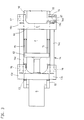
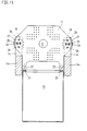
- the movable one is Mold carriers on guides of the movement path on the machine base 10 guided.
- the first two exemplary embodiments are around two guide rails 15 which are arranged on the bearing 15a and on which the movable mold carrier 12 by sliding shoes 12a is secured against lifting.
- bracket 14 are still Guide rods 21 provided on the stationary mold carrier 11 and are supported on the support element 13. You are in one Space that is closed on both sides by the bracket 14, so that they do not represent an additional obstacle in the mold clamping area F.
- the movable mold carrier is supported by support elements 12c on a horizontal 22a and a vertical tread 22b of a rail 22 are guided on the machine base 10. In the third Embodiment is omitted on the guide rods 21.
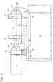
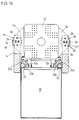
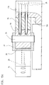
- FIGS. 17-24 acts as Closing mechanism a toggle mechanism with the articulation point 36 on the movable mold carrier 12 and with the articulation point 35 on a support element 13 '. He transfers the movable mold carrier into and out of the closed position.
- the toggle mechanism is called a "Y toggle lever" trained, i.e. its transverse to the closing direction s-s arranged drive device A is from the toggle lever mechanism Y over two holding elements 37, 38 held freely movable.
- the drive device becomes an electro-mechanical linear drive used in which a rotational movement in a straight-ahead movement is implemented.
- the toggle lever mechanism Y has two levers 42, 43, which are connected to one another via an articulation point 40. At this Joint point 40 also attacks a linear element of the linear drive.
- the Ball screw can be arranged in a hollow shaft motor H, the is also the drive device A (Fig. 22).
- the hollow shaft motor H has a stator 52 and a rotor 51 in a housing 64 Rotor 51 is connected to a sleeve 53.
- the sleeve 53 carries coaxially co-operating with the ball screw 41 Threaded nut 54. With positive locking, the rotation of the Threaded nut the ball screw 41 into the sleeve or out. If necessary, it can be pulled down from the drive device an opening 64a of the housing emerge again.
- the the Holding elements 37, 38 carrying the drive device are on Articulation points 74, 75 connected to a connector part 55, which the actual drive device carries.
- the toggle mechanism Y is vertically movable and unlockable downwards.
- the movable mold carrier 12 must be in connection with the only articulated toggle mechanism can be reliably guided.
- To it has a flat, plate-shaped and vertical part 12d and has two support parts 12e.
- the parts 12d, 12e of the Mold carrier 12 can be integrally formed or together be connected.
- the support members 12e extend both in one Area outside the mold clamping space F, as well as in the direction of the stationary mold carrier 11. This is the support surface and Area to accommodate tilting moments enlarged.
- the function of a The chute arranged in the area of the parting plane t-t is not impaired, since the support is only in the edge area, the already partially through the upper edge 10a of the Machine foot is claimed (Fig. 18).
- the support parts 12e engage behind the guides on the Mold clamping space F opposite side and are on the guides over a central angle of at least 180 °. 19 are preferably in both support parts 12e as roller cassettes 32 trained running elements installed in a known manner horizontal and vertical treads 15b one as a guide trained, provided on the machine base 10 guide rail 15 are performed. Only one horizontal and two are conceivable to provide vertical roller cassettes.
- the support part 12e engages an arm 12e 'in the machine base under the guide rail. On the arm 12e 'a rear grip element 33 is arranged, which on a flanged upper edge 10a of the machine base 10 from below is present. Instead, built in the support parts 12e Ball bearing 34, the guide rods 21 designed as guides reach around. In both cases, the wrap takes on the forces that still occur who want to lift the movable mold carrier from the machine base, to record.
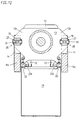
- the articulated arrangement of the "Y toggle lever” can also be advantageous in Be brought into connection with the deformation element.
- the stationary mold carrier 11 movable with at least one bracket 14 the support element 13 'connected.
- the "slipstream" of a leg 14c of the bracket 14 can guides for the support members 12e and for example, the bearings of the roller cassettes 32 in the Support elements 12c can be seen without a separate space must be claimed.
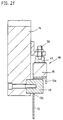
- the support element 13 ' is connected to the bracket 14 and the The bracket in turn can be designed as a bearing according to FIG. 21.
- the bearing element 46 is at an angle in the range of neutral fiber of the bracket 14 attached.
- a fine adjustment is over the adjusting element 50 possible, which is on a sliding element 49 is supported.
- the sliding element 49 takes over the actual Storage on the guide rail 15.
- the bearing elements 46 are in one in FIG plane v-v located perpendicular to the closing direction, the goes approximately through the articulation point 35. This situation was therefore chosen because this point is the hinge point for the deformation element is, so that the smallest deformations result here.
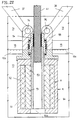
- a mold height adjustment V must be provided be a constant at different mold heights Position of the closing direction s-s allowed.
- a Spindle drive 39 is provided, which according to FIG. 18 on an abutment 44 is supported and via its threaded spindle 39a with the Support element 13 'is connected.
- the two spindle drives 39 can each be driven separately when setting up the machine be, so that there is an exact parallel setting between movable mold carrier 12 and stationary mold carrier 11 results.
- in the Both spindle drives are then in one operating state common drive 60 adjustable. Drives via a pulley 57 he two pulleys 56 for the threaded spindles over one or several straps 63 (Fig. 20). According to FIG. 18, this is the exact one Force application of disruptive thread play through disc springs 45 suppressed, which are held on a spacer 44a.
- threaded sleeves can also be provided via a second drive 62 are driven, which are designed as pulleys.
- the Threaded sleeve 62 is with its external thread on the spacer 44a in Thread engagement.
- the drive 60 can Pulley 56 are operated, which leads to an adjustment of the Lead screw 39a leads.
- the abutment 44 is the nut 71 of the Spindle drive held in a hole. After adjustment can by an opposite movement of the belt 65 of the second Drives the threaded sleeve 62 towards the spacer 44a are pressed so that the nut 71 via the threaded spindle 39a and the adjustment ring 73 is pressed.
- the threaded spindle 39a is on Support element 13 'added with play. The determination is made via Draw bolts 58 which engage a support ring 59. While dressing and thus adjusting the tension bolts, the threaded spindle 39a is countered the abutment 72 biased.
Abstract
Description
Die Erfindung betrifft eine Spritzgießmaschine
nach dem Oberbegriff des Anspruches 1.The invention relates to an injection molding machine
according to the preamble of
Eine derartige Spritzgießmaschine ist beispielsweise aus dem DE-U 92 12 480 bekannt. Bei dieser Spritzgießmaschine sind Abstützelement und Formträgerplatte gelenkig und kippbar mit einem gußeisernen Maschinenfuß verbunden, der die während des Schließens auftretende Schließkraft und die während des Einspritzens auftretende Auftriebskraft zwischen dem Abstützelement und der Formaufspannplatte ableitet. Um Ausweichbewegungen der Formplatten wie dem 'Kirschsteineffekt' zu entgehen und um eine Formparallelität zu erreichen, sind Führungen für den beweglichen Formträger vorgesehen, um diesen insbesondere bei exzentrischer Belastung beispielsweise durch außermittige Formhohlräume parallel zur anderen Formhälfte zu führen. Es wird das Prinzip verfolgt, den Maschinenfuß so steif auszubilden, daß er sich unter den entstehenden Kräften nur minimal verformt und im übrigen die verbleibenden Verformungen durch die gelenkige Lagerung von Formträgerplatte und Abstützelement von der Form fernzuhalten. Allerdings treten bei der Herstellung des gußeisernen Maschinenfußes aufgrund der Größe des Gußkörpers Schwierigkeiten durch Lunker auf. Da die stationäre Formträgerplatte am Maschinenfuß gelenkig angelenkt ist, läßt sich ein Düsennullpunkt aufgrund der beim Schließvorgang auftretenden Kräfte nicht reproduzierbar einstellen.Such an injection molding machine is for example from DE-U 92 12 480 known. This injection molding machine has support elements and mold carrier plate articulated and tiltable with a cast iron Machine foot connected, which occurs during the closing Closing force and the one that occurs during injection Buoyancy force between the support element and the platen derives. To avoid movements of the mold plates like that To escape the 'cherry stone effect' and to ensure a parallelism of form reach, guides are provided for the movable mold carrier, around this especially with eccentric loads, for example due to eccentric mold cavities parallel to the other mold half to lead. The principle is followed, the machine base so stiff to train that he is minimal under the emerging forces deformed and the remaining deformations by the articulated storage of the mold carrier plate and support element from the Keep shape out. However, in the manufacture of the cast iron machine base due to the size of the cast body Difficulties caused by blowholes. Because the stationary mold carrier plate is articulated on the machine base, a nozzle zero can be made due to the forces occurring during the closing process reproducible setting.
Aus der EP-A 504 580 ist eine Preßvorrichtung für eine Abbrennstumpfschweißmaschine bekannt, bei der ein gesondertes Kraftübertragungselement vorgesehen ist, das an beiden Enden einer Presse angelenkt ist. Zum Lösen des Kraftübertragungselements ist dieses mit Sicherungsringen an den beiden Enden gehalten, ohne daß Vorkehrungen getroffen sind, gesonderte Gelenkteile für sich austauschen zu können. Die Pressenteile selbst sind einerseits stationär mit dem Maschinenfuß verbunden und andererseits über ein Stützelement abgestützt, das sich beim Aufbringen der Preßkraft so bewegt, daß ein Anlenkungspunkt auf einem Radius gegenüber dem Verbindungspunkt mit dem Maschinenfuß bewegt wird. Dies führt zu einer vertikalen Komponente bei den Kräften und damit zu einer ungewünschten Auslenkung, die die Präzision der Vorrichtung negativ beeinflußt. From EP-A 504 580 is a pressing device for a flash butt welding machine known in which a separate power transmission element is provided, which is articulated at both ends of a press is. To release the power transmission element, this is with locking rings held at both ends without taking any precautions are able to replace separate joint parts for themselves. The press parts themselves are stationary on the one hand with the machine base connected and supported on the other hand via a support element, the moves when applying the pressing force so that a point of articulation on a radius opposite the connection point with the machine base is moved. This leads to a vertical component in the Forces and thus to an undesired deflection that the Precision of the device is negatively affected.
Aus der US-A 3,704,973 ist eine Vorrichtung bekannt, bei der an einer Formschließeinheit ein Elektromotor um eine mittig in ihm liegende Antriebsspindel angeordnet ist. Der Rotor des Elektromotors steht dabei mittelbar mit einer Gewindemutter in Verbindung, die mit der Spindel in Eingriff steht. Es handelt sich jedoch dabei noch nicht um einen Hohlwellenmotor, bei dem der Rotor zugleich die Spindelmutter ist.From US-A 3,704,973 a device is known in which on a Mold closing unit an electric motor around a centrally located in it Drive spindle is arranged. The rotor of the electric motor is stopped indirectly with a threaded nut in connection with the Spindle is engaged. However, it is not yet a hollow shaft motor in which the rotor is also the spindle nut is.
Nach der DE-A 42 30 348 sind ein Abstützelement und eine Formträgerplatte gelenkig mit einem gußeisernen Maschinenfuß verbunden, der die während des Schließens und während des Einspritzens auftretenden Kräfte ableitet. Über einen Kniehebelmechanismus, bei dem die Antriebseinrichtung an den Anlenkungspunkten des Kniehebels frei aufgehängt ist, sind der bewegliche Formträger und ein Abstützelement für den Kniehebel gelenkig miteinander verbunden, wodurch Ausweichbewegungen des beweglichen Formträgers vermieden werden. Der Maschinenfuß ist dabei nach der DE-U 92 12 480 ausgebildet.According to DE-A 42 30 348, a support element and a mold carrier plate articulated to a cast iron machine base, which during closing and during injection forces that occur. Via a toggle mechanism, at which the drive device at the articulation points of the toggle lever is freely suspended, the movable mold carrier and a support element for the toggle jointed together, whereby Evasive movements of the movable mold carrier can be avoided. Of the Machine base is designed according to DE-U 92 12 480.
In der nachveröffentlichten EP-A 554 068 wird ein Verformungselement vorgesehen, das sich verformen kann, ohne daß im wesentlichen von den Bewegungs- und Spritzkräften hervorgerufene Spannungen in den Maschinenfuß abgeleitet werden. Das Verformungselement bildet mit den weiteren Teilen der Formschließeinheit einen geschlossenen Kraftrahmen und kann den jeweiligen Einsatzbedingungen optimal angepaßt werden. Die Verformungen haben nahezu keinen Einfluß auf die Lage der festen Aufspannplatte. Am Maschinenfuß angeschraubte Peripheriegeräte, wie Handling- und Entnahmeeinrichtungen werden von den Verformungen nicht beeinflußt, so daß eine exakte Ansteuerung von Ablagepunkten reproduzierbar möglich ist. Auch der horizontale Düsennullpunkt bleibt selbst bei maximaler Zuhaltekraft bei Null stehen, da der Düsennullpunkt durch die starre Verbindung zwischen der festen Aufspannplatte und dem Maschinenfuß festgelegt ist. Es wird also das Prinzip verfolgt, die Verformungen über ein Verformungselement abzuleiten, das auf weitere Teile der Maschine keinen Einfluß hat, während die Schließkräfte ungehindert in Schließrichtung aufgebracht werden. Aufgrund der abgekoppelten Verformungen ist ein sicheres Schließen des Spritzgießwerkzeuges über den gesamten Einspritzvorgang gewährleistet. Auf Holme kann teilweise ganz verzichtet werden, wodurch ein besserer Zugang zum Spritzwerkzeug und kürzere Umrüstzeiten zu verwirklichen sind. Allerdings sind bei dieser Vorrichtung die Lagerpunkte für das Verformungselement unmittelbar am stationären Formträger und an einem Abstützelement angeformt. Sie gleiten dabei in Augen des Verformungselements. Dadurch ergeben sich einerseits Schwierigkeiten hinsichtlich der Einstellung der Formparallelität, andererseits aber treten im Laufe der Lebensdauer der Maschine Verschleiße an den Gelenken auf, die einen vollständigen Austausch von Formträger und Verformungselement erforderlich machen.In the post-published EP-A 554 068 a deformation element provided that can deform without substantially from the Tensions in the machine base caused by movement and spraying forces be derived. The deformation element forms with the other parts of the mold clamping unit a closed power frame and can be optimally adapted to the respective operating conditions become. The deformations have almost no influence on the position of the fixed platen. Peripherals screwed to the machine base, how handling and removal devices become from the deformations not affected, so that an exact control of storage points is reproducibly possible. Also the horizontal nozzle zero remains at zero even with maximum locking force, because the nozzle zero point due to the rigid connection between the fixed Platen and the machine base is fixed. So it will The principle is based on deriving the deformations via a deformation element, that has no influence on other parts of the machine, while the closing forces are freely applied in the closing direction become. Due to the decoupled deformations is a safe one Closing the injection mold over the entire injection process guaranteed. There is no need for spars at all, which means better access to the injection mold and shorter changeover times are to be realized. However, with this device the bearing points for the deformation element directly on the stationary Mold carrier and molded onto a support element. You slide in the eyes of the deformation element. This results on the one hand Difficulties with the adjustment of the shape parallelism, on the other hand, wear occurs over the life of the machine on the joints that have a full exchange of Make mold carrier and deformation element necessary.
Ausgehend von diesem Stand der Technik liegt der Erfindung die Aufgabe zugrunde, eine Spritzgießmaschine der eingangs genannten Gattung derart weiterzubilden, daß die an der Formschließeinheit auftretenden Verformungen auch nach langer Lebensdauer noch ohne Einfluß auf den Maschinenfuß abgeleitet werden, ohne die Formparallelität zu beeinträchtigen.Starting from this prior art, the object of the invention based on an injection molding machine of the type mentioned to further develop such that those occurring on the mold clamping unit Deformation even after a long service life has no effect on the Machine base are derived without affecting the parallelism of shape.
Diese Aufgabe wird durch die Merkmale des Anspruches 1 gelöst.This object is solved by the features of
Zweckmäßige Weiterbildungen der Erfindung sind in den abhängigen Ansprüchen beschrieben.Appropriate developments of the invention are described in the dependent claims.
Dadurch werden jetzt nicht mehr nur die Verformungen außerhalb der Hauptbestandteile der Formschließeinheit abgeleitet und aufgenommen, wodurch eine auf Druck beanspruchte formschlüssige Verbindung zwischen den Teilen entsteht, die einen sicheren Aufbau der Schließkraft gewährleistet, sondern durch die lösbare Befestigung der Gelenkteile und die Anordnung der Gelenke läßt sich die Formparallelität leicht ein- und nachjustieren. Durch die Anordnung der Gelenke wird die Biegebeanspruchung der Formträger reduziert, was eine geringere Dimensionierung der Formträger erlaubt und somit zur Bauhöhenreduzierung beiträgt. Bei Verschleiß der Gelenke lassen sich diese Teile leicht austauschen, ohne daß gleichzeitig nahezu die gesamte Formschließeinheit ausgetauscht werden muß. Die lösbare Befestigung der Gelenke schafft aber auch die baulichen Voraussetzungen für eine leichte Veränderbarkeit der Formaufspannmaße. Gleichzeitig sind die Verformungen von Maschinenfuß und Peripheriegeräten abgekoppelt. Ein Düsennullpunkt liegt unveränderlich fest. Auf Holme kann verzichtet werden. As a result, the deformations are no longer just outside the Main components of the mold clamping unit are derived and recorded, which creates a positive connection under pressure the parts that create a secure build of the clamping force guaranteed, but by the releasable attachment of the joint parts and the arrangement of the joints makes the shape parallelism easy adjust and readjust. By arranging the joints the bending stress of the mold carrier is reduced, which is less Dimensioning of the mold carriers allowed and thus to reduce the overall height contributes. When the joints wear out, replace these parts easily, without almost the same time Entire mold clamping unit must be replaced. The detachable attachment the joints also create the structural conditions for easy changeability of the mold clamping dimensions. At the same time are the deformations of the machine base and peripheral devices uncoupled. A nozzle zero is fixed. On spars can be dispensed with.
Soll das Formaufspannmaß wie im asiatischen Raum aufgrund des dortigen Werkzeugbaus oft üblich, verändert werden, können Unterlegstücke vorgesehen werden (Anspruch 4).Should the mold clamping dimension be like in Asia due to the Tooling there, which is often common, can be changed be provided (claim 4).
Nach Anspruch 5 wird ein Kniehebelmechanismus vorgesehen, dessen
Gelenke zugleich als Gelenke zur Anlenkung des Kraftübertragungselements
dienen. Der Kniehebelmechanismus ist ein sogenannter "Y-Kniehebel",
so daß sich eine äußerst platzsparende Bauweise der Formschließeinheit
ergibt, wenngleich für diese Antriebseinrichtung ein
überschaubarer Raum vorgesehen werden muß.According to
Eine Ausgestaltung gemäß Anspruch 6 hat den Vorteil, daß eine Kugelrollspindel ohne gesonderten Raumbedarf im Innern des Hohlwellenmotors geführt werden kann. Zudem entfällt beim Hohlwellenmotor ein zusätzliches Übersetzungsgetriebe, so daß der Raumbedarf im Maschinenfuß, der die Antriebseinrichtung aufnimmt, noch weiter minimiert ist.An embodiment according to claim 6 has the advantage that a ball screw without special space inside the Hollow shaft motor can be performed. In addition, the Hollow shaft motor an additional transmission gear, so that the Space requirement in the machine base, which accommodates the drive device, is further minimized.
Da sowohl beweglicher Formträger als auch Hebelmechanismus kürzer gebaut werden, wird der Bügel kürzer und damit leichter. Die Verwendung des Verformungselementes Bügel hat den Vorteil, daß im "Windschatten" des Bügels Führungen vorgesehen werden können, so daß die in den Formspannraum reichenden Führungen in einem Raum angeordnet werden können, der ohnehin durch die Bügel für eine Gießform nur noch bedingt zugänglich ist. Bei Verwendung eines frei verformbaren Verformungselementes muß die gesamte Formschließeinheit an einem zweiten Punkt zuverlässig und axial beweglich abgestützt werden. Bei einem Kniehebelmechanismus ist dazu nicht unbedingt ein Abstützelement erforderlich, da lediglich eine gelenkige Verbindung mit dem Verformungselement nötig ist. Um den Aufwand und den Platzbedarf für die Abstützplatte zu sparen, wird gemäß Anspruch 7 der zweite gegenüber dem Maschinenfuß axial bewegliche Lagerungspunkt der Formschließeinheit so gewählt, daß er im Bereich des Anlenkungspunktes des Kniehebelmechanismus auf der vom beweglichen Formträger abgewandten Seite angeordnet ist. Die Anlenkung erfolgt ohne Störung der Funktionsweise des Bügels am Bügel selbst, vorzugsweise im Bereich der neutralen Faser.Because both the movable mold carrier and the lever mechanism are shorter are built, the bracket becomes shorter and therefore lighter. The Use of the deformation element bracket has the advantage that in "Slipstream" of the bracket guides can be provided so that the guides in the mold clamping space in a room can be arranged by the bracket for a anyway Casting mold is only partially accessible. When using a free deformable deformation element must the entire mold clamping unit supported reliably and axially movable at a second point become. With a toggle mechanism, this is not necessarily one Support element required, since only an articulated connection with the deformation element is necessary. To the effort and the Saving space for the support plate is according to claim 7 the second bearing point that is axially movable relative to the machine base the mold clamping unit chosen so that it in the area of Articulation point of the toggle mechanism on that of the movable The side facing away from the mold carrier is arranged. The linkage takes place without disturbing the functioning of the bracket on the bracket itself, preferably in the area of the neutral fiber.
Im folgenden werden mehrere Ausführungsbeispiele der Erfindung anhand der Zeichnungen beschrieben. Es zeigen:
- Fig. 1
- eine Seitenansicht der Formschließeinheit der Spritzgießmaschine,
- Fig. 2
- einen Schnitt gemäß Linie 2-2 von Fig. 1,
- Fig. 3
- eine Draufsicht auf die Formschließeinheit gemäß Fig. 1,
- Fig. 4, 5
- Schnitte gemäß den Linien 4-4, 5-5 von Fig. 1,
- Fig. 6
- ein Verformungsbild der Spritzgießmaschine in einer Ansicht gemäß Fig. 1,
- Fig. 7, 8
- Darstellungen der Spritzgießmaschine in Ansichten gemäß Fig. 1, 2 eines weiteren Ausführungsbeispiels,
- Fig. 9-13
- Darstellungen einer dritten Ausführungsform in Ansichten gemäß den Fign. 1-5 mit einem veränderten Verformungselement,
- Fig. 14,15
- Seitenansicht und teilweise geschnittene Draufsicht der gelenkigen Lagerung im dritten Ausführungsbeispiel,
- Fig. 15a
- eine Darstellung gemäß Fig. 15 mit einem Unterlegstück,
- Fig. 16
- die Spritzgießmaschine in einer Ansicht gemäß Fig. 1 in einer vierten Ausführungsform mit einem Schwenkrahmen,
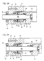
- Fig. 17
- ein fünftes Ausführungsbeispiel der Formschließeinheit in einer Seitenansicht mit einem "Y-Kniehebel",
- Fig. 18
- eine Draufsicht auf die Formschließeinheit gemäß Fig. 17,
- Fig. 19
- einen Schnitt durch die Formschließeinheit gemäß Linie 19-19 von Fig. 17,
- Fig. 20
- einen Schnitt durch die Formschließeinheit gemäß Linie 20-20 von Fig. 17,
- Fig. 21
- einen vergrößerten Ausschnitt gemäß Linie 21-21 von Fig. 17 im Bereich der Lagerung,
- Fig. 22
- einen geschnittenen vergrößerten Ausschnitt aus Fig. 17 im Bereich eines Hohlwellenmotors,
- Fig. 23,24
- einen Schnitt durch die Formhöhenverstelleinrichtung von Fig. 17 im Bereich eines Spindelantriebs bei unterschiedlichen Formhöhen,
- Fig. 1
- a side view of the mold clamping unit of the injection molding machine,
- Fig. 2
- 2 shows a section along line 2-2 of FIG. 1,
- Fig. 3
- 2 shows a plan view of the mold clamping unit according to FIG. 1,
- 4, 5
- Cuts according to lines 4-4, 5-5 of Fig. 1,
- Fig. 6
- 2 shows a deformation image of the injection molding machine in a view according to FIG. 1,
- 7, 8
- Representations of the injection molding machine in views according to FIGS. 1, 2 of a further exemplary embodiment,
- Fig. 9-13
- Representations of a third embodiment in views according to FIGS. 1-5 with a modified deformation element,
- Fig. 14.15
- Side view and partially cut top view of the articulated bearing in the third embodiment,
- 15a
- 15 with a washer,
- Fig. 16
- 1 in a fourth embodiment with a swivel frame,
- Fig. 17
- a fifth embodiment of the mold clamping unit in a side view with a "Y toggle",
- Fig. 18
- 17 shows a plan view of the mold clamping unit according to FIG. 17,
- Fig. 19
- 4 shows a section through the mold clamping unit according to line 19-19 of FIG. 17,
- Fig. 20
- 2 shows a section through the mold clamping unit according to line 20-20 of FIG. 17,
- Fig. 21
- 17 shows an enlarged section according to line 21-21 of FIG. 17 in the area of the bearing,
- Fig. 22
- 17 shows a cut enlarged section from FIG. 17 in the region of a hollow shaft motor,
- Fig. 23.24
- 17 shows a section through the mold height adjustment device from FIG. 17 in the region of a spindle drive with different mold heights,
Allen Ausführungsbeispielen ist gemeinsam, daß auf einem Maschinenfuß
10 oder einem Teil davon wie z.B. einem Schwenkrahmen 29 ein
stationärer Formträger 11 und ein beweglicher Formträger 12 angeordnet
sind. Für die Bewegung des beweglichen Formträgers 12 ist ein
Schließmechanismus S vorgesehen, der an einem Abstützelement 13
angeordnet ist. Das Abstützelement 13 ist mit dem stationären
Formträger über wenigstens ein Kraftübertragungselement beweglich
verbunden, das im wesentlichen die bei geschlossener Gießform 31
auftretenden Schließ- und Spritzkräfte aufnimmt. Der bewegliche
Formträger 11 bewegt sich entlang einer Bewegungsbahn, vorzugsweise
auf Führungen 15, 22. Die Formträger weisen zwischen sich einen
Formspannraum F für eine Gießform 31 in Fig. 17 auf. Sowohl am
stationären Formträger 11 als auch am beweglichen Formträger 12 sind
Teile der Gießform 31 festlegbar.All of the exemplary embodiments have in common that on a
Das Kraftübertragungselement überträgt nicht nur die Kräfte, sondern
ist als gesondertes, durch die Kräfte verformbares,
Verformungselement und in den Ausführungsbeispielen als Bügel 14
ausgebildet. Die Bügelform ermöglicht zwar den leichten Zugang zum
Formspannraum, jedoch sind auch andere Formen möglich. Der stationäre
Formträger 11 ist über Befestigungselemente 23 am Maschinenfuß
befestigt. Demgegenüber sind sämtliche anderen Teile der
Formschließeinheit, also insbesondere beweglicher Formträger und
Abstützelement gegenüber dem Maschinenfuß beweglich. In den Figuren
erkennt man, daß das Abstützelement lediglich an der Schiene 22 oder
der Führungsschiene 15 beweglich gepratzt ist und gegenüber dem
Maschinenfuß längs der Schließrichtung beweglich ist. Werden Kräfte
aufgebracht, so nehmen diese keinen Einfluß auf den Maschinenfuß, da
es im wesentlichen nach Ableitung der sonstigen Verformungen nur noch
zu einer vom Maschinenfuß unabhängigen Axialbewegung in
Schließrichtung kommt.The power transmission element not only transmits the forces, but
is a separate, deformable by the forces,
Deformation element and in the exemplary embodiments as a
Aus einem Vergleich der Fig. 1 und 6 ist ersichtlich, daß durch das
Verformungselement 14 eine Entkopplung der Verformungen von den in
Schließrichtung wirkenden Axialkräften möglich wird. Dazu ist das
Verformungselement frei aufgehängt und mit dem Abstützelement 13 und
dem stationären Formträger 11 gelenkig verbunden. Das Verformungselement
wird durch zwei C-förmige Bügel 14 gebildet, wodurch die
Einspritzöffnung E freigehalten ist. Die Anlenkung des Bügels am
stationären Formträger und dem Abstützelement 13 erfolgt über
Lagerelemente.From a comparison of FIGS. 1 and 6 it can be seen that by
Deformation element 14 a decoupling of the deformations from the in
Axial forces acting in the closing direction is possible. That’s it
Deformation element freely suspended and with the
In den ersten beiden Ausführungsbeispielen ist der C-förmige Bügel 14
an Anformungen 11c, 13c von stationärem Formträger und Abstützelement
13 angelenkt. In einer Ausnehmung der Anformung 11c ist der Bolzen 17
gelagert, der ein Auge 14d des Bügels 14 durchgreift. Auf der anderen
Seite ist der Bügel 14 über Bolzen 16 mit der Anformung 13c der als
Abstützelement ausgebildeten Zylinderplatte verbunden, wobei der
Anlenkungspunkt zwischen Zylinderplatte und beweglichem Formträger 12
liegt.In the first two exemplary embodiments, the C-shaped
Im dritten Ausführungsbeispiel (Fig. 9-15a) werden Bolzen 17 und 18
vorgesehen, die als Teile eines Lagers durch Schrauben 25 am
stationären Formträger 11 oder an dem Abstützelement 13 befestigt
sind (Fig. 15, 16). Die Bolzen stehen über ein Gleitlager 28 mit
einem Lagerbock 27 in Verbindung, der mit Schrauben 26 am Bügel 14
befestigt ist. Dadurch lassen sich die Kräfte momentenfrei
übertragen.In the third exemplary embodiment (FIGS. 9-15a),
Im vierten Ausführungsbeispiel sind Bolzen 17 und 18 so angeordnet,
daß sie beim Formschluß formschlüssig zwischen stationärem Formträger
11 und Bügel 14 bzw. Abstützelement 13 und Bügel 14 aufgenommen sind.
Der Anlenkungspunkt im Bereich des Abstützelements 13 ist auf der vom
beweglichen Formträger 12 abgewandten Seite des Abstützelements
angeordnet. In Fig. 16 ist zu erkennen, daß die Bolzen 17, 18 in
Ausnehmungen 11a, 13a, 14a des Bügels 14, des stationären Formträgers
11 und des Abstützelements 13 gelagert sind. Sie werden senkrecht zu
ihrer Achse von weiteren Lagerbolzen 19 durchgriffen, die in
Bohrungen 11b, 13b, 14b von Bügel 14, stationärem Formträger 11 oder
Abstützelement 13 eintauchen. Beim Formschluß gelangen die
Lagerbolzen 19 gegen die Kraft von Federn 20 in die Bohrungen 11b,
13b von stationärem Formträger und Abstützelement 13. Diese Anordnung
unterstützt die Überwindung der Entformkräfte, führt jedoch auch zu
Reibkräften, die die Abkopplung von den Verformungen erschweren. Die
unterschiedlichen Anordnungsmöglichkeiten des Bügels schaffen eine
vom Stand der Technik unerreichte Anpassungsfähigkeit an
Kundenwünsche z.B. hinsichtlich unterschiedlicher Werkzeugeinbaumaße,
wenn der Bügel vor oder hinter dem Abstützelement angelenkt wird. Die
Gelenkteile Bolzen 16, 17,18 und Lagerbock 27 der Gelenke sind durch
Schrauben an den gelenkig miteinander verbundenen Teilen der
Schließeinheit lösbar befestigt. Falls erforderlich, können längere
Schrauben 25' in Verbindung mit Unterlegstücken 75 eine Veränderung
des Werkzeugeinbaumaßes ermöglichen, die zwischen den Gelenkteilen
und den angrenzenden Bauteilen einfügbar sind (Fig. 15a).In the fourth embodiment,
Während im ersten Ausführungsbeispiel der Bügel 14 außerhalb des
Maschinenfußes 10 angeordnet ist (Fig. 2), was zu einem
verhältnismäßig schmalen Maschinenfuß führt, ist im zweiten
Ausführungsbeispiel der Bügel 14 innerhalb des Maschinenfußes und
auch innerhalb der Führungsschienen 15 angeordnet. Um den beweglichen
Formträger dennoch auf den Führungsschienen zu führen, besitzt der
bewegliche Formträger 12 Anformungen 12b, die den Bügel übergreifen,
um den beweglichen Formträger auf dem Maschinenfuß 10 zu bewegen. Ein
Vergleich der Figuren 2 und 8 macht deutlich, daß aufgrund der innen
liegenden Anordnung des Bügels ein breiterer Maschinenfuß
erforderlich ist, der bessere Aufnahmemöglichkeiten für Bauteile der
Maschine bietet. Der Bügel 14 kann auch weitgehend oberhalb der
Spritzachse s-s angeordnet sein und die Spritzgießmaschine nach oben
abschließen. Dies verdeutlicht, daß die Formschließeinheit von der
Anordnung des Bügels unabhängig ist, was ihr eine Vielfalt von
Einsatzmöglichkeiten eröffnet. Problemlos kann die Formschließeinheit
um einen Schwenkbolzen 30 mitsamt einem Schwenkrahmen 29 in eine
vertikale Stellung überführt werden (Fig. 16). Abweichend von den
Ausführungsbeispielen können auch mehrere Bügel gleichzeitig
innerhalb, außerhalb und/oder auf dem Maschinenfuß angeordnet werden,
um z.B. größere Kräfte übertragen zu können.While in the first embodiment, the
Um eine Formparallelität zu gewährleisten, ist der bewegliche
Formträger auf Führungen der Bewegungsbahn am Maschinenfuß 10
geführt. In den ersten beiden Ausführungsbeispielen handelt es sich
um zwei Führungsschienen 15, die auf dem Lager 15a angeordnet sind
und auf denen der bewegliche Formträger 12 durch Gleitschuhe 12a
gegen Abheben gesichert ist. Nach dem vierten Ausführungsbeispiel
(Fig. 16) sind trotz des Verformungselementes Bügel 14 noch
Führungsstangen 21 vorgesehen, die am stationären Formträger 11 und
an dem Abstützelement 13 gelagert sind. Sie befinden sich in einem
Raum, der nach beiden Seiten durch den Bügel 14 abgeschlossen ist, so
daß sie kein zusätzliches Hindernis im Formspannraum F darstellen. In order to ensure parallelism of form, the movable one is
Mold carriers on guides of the movement path on the
Sie liegen also in einem Bereich, der durch die vertikale Abmessung
des Schenkels 14c des Bügels vorgegeben ist. Die eigentliche
Abstützung des beweglichen Formträgers erfolgt über Stützelemente
12c, die an einer horizontalen 22a und einer vertikalen Lauffläche
22b einer Schiene 22 am Maschinenfuß 10 geführt sind. Im dritten
Ausführungsbeispiel wird auf die Führungsstangen 21 verzichtet.So they are in an area defined by the vertical dimension
of the leg 14c of the bracket is predetermined. The real one
The movable mold carrier is supported by
Im fünften Ausführungsbeispiel der Fign. 17-24 greift als
Schließmechanismus ein Kniehebelmechanismus mit dem Anlenkungspunkt
36 am beweglichen Formträger 12 an und mit dem Anlenkungspunkt 35 an
einem Abstützelement 13'. Er überführt den beweglichen Formträger in
und außer Schließposition. Der Kniehebelmechanismus ist als "Y-Kniehebel"
ausgebildet, d.h., seine quer zur Schließrichtung s-s
angeordnete Antriebseinrichung A wird vom Kniehebelmechanismus Y über
zwei Halteelemente 37, 38 frei beweglich gehalten. Als
Antriebseinrichtung wird ein elektro-mechanischer Linearantrieb
verwendet, bei dem eine Rotationsbewegung in eine Geradeausbewegung
umgesetzt wird. Der Kniehebelmechanismus Y besitzt zwei Hebel 42, 43,
die über einen Gelenkpunkt 40 miteinander verbunden sind. An diesem
Gelenkpunkt 40 greift auch ein Linearelement des Linearantriebes an.In the fifth embodiment of FIGS. 17-24 acts as
Closing mechanism a toggle mechanism with the
Als Linearantrieb kann z.B. eine Kugelrollspindel vorgesehen werden,
aber auch eine Doppelzahnstange 41' ist einsetzbar. Die
Kugelrollspindel kann in einem Hohlwellenmotor H angeordnet sein, der
zugleich die Antriebseinrichtung A ist (Fig.22). Der Hohlwellenmotor
H besitzt in einem Gehäuse 64 einen Stator 52 und einen Rotor 51. Der
Rotor 51 steht mit einer Hülse 53 in Verbindung. Die Hülse 53 trägt
koaxial eine mit der Kugelrollspindel 41 zusammenwirkende
Gewindemutter 54. Bei Formschluß bewegt sich infolge der Rotation der
Gewindemutter die Kugelrollspindel 41 in die Hülse hinein oder
heraus. Bedarfsweise kann sie unten aus der Antriebseinrichtung über
eine Öffnung 64a des Gehäuses wieder austreten. Die die
Antriebseinrichtung tragenden Halteelemente 37,38 sind an
Anlenkungspunkten 74,75 mit einem Verbinderteil 55 verbunden, das die
eigentliche Antriebseinrichtung trägt. Der Kniehebelmechanismus Y ist
vertikal beweglich und nach unten entriegelbar. As a linear drive e.g. a ball screw can be provided
but a double rack 41 'can also be used. The
Ball screw can be arranged in a hollow shaft motor H, the
is also the drive device A (Fig. 22). The hollow shaft motor
H has a
Der bewegliche Formträger 12 muß in Verbindung mit dem nur
angelenkten Kniehebelmechanismus zuverlässig geführt werden. Dazu
weist er einen flachen, plattenförmigen und senkrecht stehenden Teil
12d auf und besitzt zwei Stützteile 12e. Die Teile 12d, 12e des
Formträgers 12 können einstückig ausgebildet oder miteinander
verbunden sein. Die Stützteile 12e erstrecken sich sowohl in einem
Bereich außerhalb des Formspannraumes F, als auch in Richtung auf den
stationären Formträger 11. Dadurch wird die Abstützfläche und die
Fläche zur Aufnahme von Kippmomenten vergrößert. Die Funktion eines
im Bereich der Trennebene t-t angeordneten Fallschachtes wird nicht
beeinträchtigt, da die Abstützung nur im Randbereich erfolgt, der
ohnehin bereits teilweise durch den oberen Rand 10a des
Maschinenfußes beansprucht wird (Fig. 18).The
Die Stützteile 12e hintergreifen die Führungen auf der dem
Formspannraum F gegenüberliegenden Seite und sind an den Führungen
über einen Zentriwinkel von wenigstens 180° geführt. Gemäß Fig. 19
sind in beiden Stützteilen 12e vorzugsweise als Rollenkassetten 32
ausgebildete Laufelemente eingebaut, die in bekannter Weise an
horizontalen und vertikalen Laufflächen 15b einer als Führung
ausgebildeten, auf dem Maschinenfuß 10 vorgesehenen Führungsschiene
15 geführt sind. Denkbar ist dabei nur eine horizontale und zwei
vertikale Rollenkassetten vorzusehen. Das Stützteil 12e greift mit
einem Arm 12e' in den Maschinenfuß unter die Führungsschiene. Am Arm
12e' ist ein Hintergriffselement 33 angeordnet, das auf einem
umgebördelten oberen Rand 10a des Maschinenfußes 10 von unten
anliegt. Stattdessen können auch in die Stützteile 12e eingebaute
Kugellager 34 die als Führungen ausgebildete Führungsstangen 21
umgreifen. In beiden Fällen nimmt der Umgriff noch auftretende Kräfte
auf, die den beweglichen Formträger vom Maschinenfuß abheben wollen,
aufzunehmen.The
Die gelenkige Anordnung des "Y-Kniehebels" kann auch vorteilhaft in
Verbindung mit dem Verformungselement gebracht werden. Hierzu ist der
stationäre Formträger 11 über wenigstens einen Bügel 14 beweglich mit
dem Ab-stützelement 13' verbunden. Im "Windschatten" eines Schenkels
14c des Bügels 14 können Führungen für die Stützteile 12e und
beispielsweise die Lagerungen der Rollenkassetten 32 in den
Stützelementen 12c vor-gesehen werden, ohne daß ein gesonderter Raum
beansprucht werden muß.The articulated arrangement of the "Y toggle lever" can also be advantageous in
Be brought into connection with the deformation element. For this is the
Das Abstützelement 13' steht mit dem Bügel 14 in Verbindung und der
Bügel seinerseits kann als Lagerung gemäß Fig. 21 ausgebildet werden.
Das Lagerelement 46 wird dabei über einen Winkel im Bereich der
neutralen Faser des Bügels 14 befestigt. Eine Feinjustierung ist über
das Justierelement 50 möglich, das auf einem Gleitelement 49
abgestützt ist. Das Gleitelement 49 übernimmt die eigentliche
Lagerung auf der Führungsschiene 15. Um beim Anheben der
Formschließeinheit ein Abheben vom Maschinenfuß zu vermeiden, ist ein
weiteres Element 48 in einer Ausnehmung 10b des Maschinenfußes axial
beweglich gelagert. Dieses Element kommt grundsätzlich mit dem
Maschinenfuß nicht in Berührung. Erst im Falle eines Anhebeversuches
wird eine Verbindung zwischen Formschließeinheit und Maschinenfuß
hergestellt. Die Lagerelemente 46 sind nach Fig. 17 in einer
senkrecht zur Schließrichtung gelegenen Ebene v-v angeordnet, die
ungefähr durch den Anlenkungspunkt 35 geht. Diese Lage wurde deshalb
gewählt, da dieser Punkt der Gelenkpunkt für das Verformungselement
ist, so daß sich hier die geringsten Verformungen ergeben.The support element 13 'is connected to the
Bei einem Kniehebelmechanismus muß eine Formhöhenverstellung V vorgesehen
sein, die bei unterschiedlichen Formhöhen eine gleichbleibende
Lage der Schließrichtung s-s erlaubt. Zu diesem Zweck ist ein
Spindelantrieb 39 vorgesehen, der gemäß Figur 18 an einem Widerlager
44 abgestützt ist und über seine Gewindespindel 39a mit dem
Abstützelement 13' in Verbindung steht. Die zwei Spindelantriebe 39
können dabei beim Einrichten der Maschine je gesondert angetrieben
werden, so daß sich eine exakte Paralleleinstellung zwischen
beweglichem Formträger 12 und stationärem Formträger 11 ergibt. Im
Betriebszustand sind dann beide Spindelantriebe über einen
gemeinsamen Antrieb 60 verstellbar. Über eine Riemenscheibe 57 treibt
er zwei Riemenscheiben 56 für die Gewindespindeln über einen oder
mehrere Riemen 63 an (Fig.20). Gemäß Figur 18 wird das die exakte
Kraftaufbringung störende Gewindespiel durch Tellerfedern 45
unterdrückt, die an einem Abstandshalter 44a gehalten sind. With a toggle mechanism, a mold height adjustment V must be provided
be a constant at different mold heights
Position of the closing direction s-s allowed. For this purpose is a
Gemäß Fig. 23-24 können auch über einen zweiten Antrieb Gewindehülsen
62 angetrieben werden, die als Riemenscheiben ausgebildet sind. Die
Gewindehülse 62 ist mit ihrem Außengewinde am Abstandshalter 44a im
Gewindeeingriff. Im gelösten Zustand kann über den Antrieb 60 die
Riemenscheibe 56 betätigt werden, was zu einem Verstellen der
Gewindespindel 39a führt. Im Widerlager 44 ist die Mutter 71 des
Spindelantriebs in einer Bohrung gehalten. Nach erfolgter Verstellung
kann durch eine gegenläufige Bewegung des Riemens 65 des zweiten
Antriebs die Gewindehülse 62 in Richtung auf den Abstandshalter 44a
gepreßt werden, so daß die Mutter 71 über die Gewindespindel 39a und
den Verstellring 73 festgepreßt wird. Die Gewindespindel 39a ist am
Abstützelement 13' mit Spiel aufgenommen. Die Festlegung erfolgt über
Zugbolzen 58, die an einem Abstützring 59 angreifen. Beim Anziehen
und somit Justieren der Zugbolzen wird die Gewindespindel 39a gegen
das Widerlager 72 vorgespannt.23-24, threaded sleeves can also be provided via a
Claims (7)
- Injection moulding machine with a machine base (10), a stationary mould carrier (11) securely connected to the machine base or a part of same, and a movable mould carrier (12), as well as with a supporting element (13) bearing a closing mechanism (S) for the movement of the movable mould carrier (12), said supporting element being hinged to the stationary mould carrier (11) via at least one force transmitting element, which substantially takes up the forces occurring when the mould (31) is closed, as well as with a motion path for the movable mould carrier (12), characterised in that the force transmitting element is configured as a deforming element (14), deformable by the forces, in that the supporting element (13) is mounted on the machine base (10) by means of a guiding device (15, 21, 22) so as to be movable in a straight line in the closing direction, joint parts (16, 17, 18; 27) for the hinged connection being detachably arranged on the supporting element (13) or stationary mould carrier (11) and on the deforming element (14).
- Injection moulding machine according to claim 1, characterised in that studs (17, 18) are detachably fastened with screws (25) to the supporting element (13) and the stationary mould carrier (11) and form joints with pillow blocks (27) detachably fastened by means of screws (26) to the deforming element configured as a shackle (14).
- Injection moulding machine according to claim 2, characterised in that the stud (17, 18) is mounted in recesses (11a,13a,14a) of the shackle (14) and of the stationary mould carrier (11) or of the supporting element (13) and is penetrated by further bearing pins (19) standing vertical to the stud axis and plunging into bore holes (11b,13b,14b) of the shackle (14) and stationary mould carrier (11) or supporting element (13).
- Injection moulding machine according to one of the preceding claims, characterised in that the distance between the stationary (11) mould carrier and the movable mould carrier (12) may be altered by washer pieces (75), which may be inserted between joint parts and the stationary mould carrier (11) supporting element (13) and/or deforming element.
- Injection moulding machine according to one of the preceding claims, characterised in that the closing mechanism is a toggle mechanism (Y) and in that a joining element (55) is suspended in an articulated manner via two holding elements (37, 38) linked to link points (35, 36) of the toggle mechanism (Y) on the movable mould carrier (12) and on the supporting element (13'), and the driving unit (A) is fastened to said joining element (55).
- Injection moulding machine according to claim 5, characterised in that that the driving device is configured as a quill drive (H) in which a ball rolling spindle (41) configured as the driving element is mounted and may be at least partially received.
- Injection moulding machine according to claim 5 or 6, characterised in that the shackle (14) carries the supporting element (13') at the machine base (10) in the area of the neutral fibres of the shackle (14), so as to be movable in the closing direction (s-s), via bearing elements (46) which are disposed in a plane (v-v) which is perpendicular to the closing direction and passes approximately through the link point (35) of the toggle mechanism (Y).
Applications Claiming Priority (6)
| Application Number | Priority Date | Filing Date | Title |
|---|---|---|---|
| DE4308962 | 1993-03-20 | ||
| DE19934308962 DE4308962C2 (en) | 1993-03-20 | 1993-03-20 | Mold clamping unit for an injection molding machine |
| DE4313473A DE4313473C2 (en) | 1993-03-20 | 1993-04-24 | Closing unit for an injection molding machine |
| DE4313473 | 1993-04-24 | ||
| DE19934323395 DE4323395C2 (en) | 1993-07-13 | 1993-07-13 | Closing unit for a plastic injection molding machine |
| DE4323395 | 1993-07-13 |
Publications (3)
| Publication Number | Publication Date |
|---|---|
| EP0620095A2 EP0620095A2 (en) | 1994-10-19 |
| EP0620095A3 EP0620095A3 (en) | 1995-01-04 |
| EP0620095B1 true EP0620095B1 (en) | 1999-01-07 |
Family
ID=27204880
Family Applications (1)
| Application Number | Title | Priority Date | Filing Date |
|---|---|---|---|
| EP93115689A Expired - Lifetime EP0620095B1 (en) | 1993-03-20 | 1993-09-29 | Injection moulding machine |
Country Status (3)
| Country | Link |
|---|---|
| EP (1) | EP0620095B1 (en) |
| AT (1) | ATE175380T1 (en) |
| DE (1) | DE59309279D1 (en) |
Cited By (1)
| Publication number | Priority date | Publication date | Assignee | Title |
|---|---|---|---|---|
| DE102006061969B4 (en) * | 2006-12-21 | 2009-12-17 | Karl Hehl | Method for operating an injection molding machine with two toggle mechanisms |
Families Citing this family (6)
| Publication number | Priority date | Publication date | Assignee | Title |
|---|---|---|---|---|
| EP0646448B1 (en) * | 1993-09-30 | 1999-10-06 | Karl Hehl | Injection moulding machine for processing plastifiable materials |
| US5811141A (en) * | 1994-12-20 | 1998-09-22 | Krauss-Maffei Ag | Mold-closing apparatus for an injection-molding machine |
| BR9800139C1 (en) * | 1998-03-23 | 2000-03-14 | Ind Romi S A Ind Romi S A | Development in mold locking mechanism |
| EP1361947B1 (en) * | 2001-02-15 | 2004-12-08 | Mannesmann Plastics Machinery GmbH | Closing device in an injection moulding machine for synthetic materials |
| AT511653B1 (en) * | 2011-06-15 | 2014-08-15 | Smc Pneumatik Ges M B H | DEVICE FOR LIFTING AND FIXING |
| US10940615B2 (en) * | 2016-03-31 | 2021-03-09 | Kyoraku Co., Ltd. | Mold clamping device |
Family Cites Families (12)
| Publication number | Priority date | Publication date | Assignee | Title |
|---|---|---|---|---|
| US2266129A (en) * | 1938-11-05 | 1941-12-16 | Sterling Injection Molding Inc | Thermoplastic molding machine |
| DE1116386B (en) * | 1958-06-07 | 1961-11-02 | Arburg Feingeraete Fabrik O H | Hydraulic or pneumatic drive device for actuating a mold clamping unit for injection molding machines that process thermoplastics |
| US3577596A (en) * | 1968-06-26 | 1971-05-04 | Vigeant Gaston | Two-phase mold press |
| US3704973A (en) * | 1971-06-08 | 1972-12-05 | Husky Mfg & Toolworks Ltd | Electro-hydraulic means for opening and closing injection molds |
| DE3145973C1 (en) * | 1981-11-20 | 1983-05-19 | Karl 7298 Loßburg Hehl | Plastic injection molding machine with mold closing unit mounted on guide rails |
| JP2673814B2 (en) * | 1988-04-06 | 1997-11-05 | ファナック株式会社 | Molding device for injection molding machine |
| CH680916A5 (en) * | 1989-11-10 | 1992-12-15 | Vickers Inc | |
| EP0504580A3 (en) * | 1991-03-20 | 1993-02-03 | H.A. Schlatter Ag | Press device and flash butt-welding machine equipped with such a device |
| AT397228B (en) * | 1991-09-12 | 1994-02-25 | Engel Gmbh Maschbau | INJECTION MOLDING MACHINE |
| AT398290B (en) * | 1991-09-18 | 1994-11-25 | Engel Gmbh Maschbau | INJECTION MOLDING MACHINE |
| DE4141259C2 (en) * | 1991-12-14 | 1993-10-07 | Hemscheidt Maschtech Schwerin | Mold closing device for injection molding machines |
| IL100832A (en) * | 1992-01-31 | 1994-01-25 | Ziv Av Amir | Clamping assembly for an injection moulding apparatus |
-
1993
- 1993-09-29 EP EP93115689A patent/EP0620095B1/en not_active Expired - Lifetime
- 1993-09-29 DE DE59309279T patent/DE59309279D1/en not_active Expired - Fee Related
- 1993-09-29 AT AT93115689T patent/ATE175380T1/en active
Cited By (1)
| Publication number | Priority date | Publication date | Assignee | Title |
|---|---|---|---|---|
| DE102006061969B4 (en) * | 2006-12-21 | 2009-12-17 | Karl Hehl | Method for operating an injection molding machine with two toggle mechanisms |
Also Published As
| Publication number | Publication date |
|---|---|
| EP0620095A2 (en) | 1994-10-19 |
| DE59309279D1 (en) | 1999-02-18 |
| ATE175380T1 (en) | 1999-01-15 |
| EP0620095A3 (en) | 1995-01-04 |
Similar Documents
| Publication | Publication Date | Title |
|---|---|---|
| EP0311133B2 (en) | Injection moulding machine | |
| EP0722820B1 (en) | Tie bar-less mould clamping device | |
| AT402811B (en) | INJECTION MOLDING MACHINE | |
| EP0300223A2 (en) | Device for closing moulds for producing articles from a thermoplastic resin | |
| EP0668817A1 (en) | Injection moulding machine | |
| DE4313473C2 (en) | Closing unit for an injection molding machine | |
| EP1802441B1 (en) | Closing unit for an injection moulding machine comprising a stack mould | |
| DE602004007562T2 (en) | Clamping device for an injection molding machine | |
| EP0626245B1 (en) | Mould closing unit for a plastic injection moulding machine | |
| EP0646448B1 (en) | Injection moulding machine for processing plastifiable materials | |
| EP0687541B1 (en) | Tie bar-less mould clamping device for injection moulding machines | |
| EP0620095B1 (en) | Injection moulding machine | |
| EP0631857B1 (en) | Plastic injection moulding machine with a mould closing unit | |
| EP0770468A2 (en) | Two-platen tie bar-less injection moulding machine | |
| EP0754534B1 (en) | Apparatus for plastic injection moulding | |
| WO1996019331A1 (en) | Die clamp for plastic moulding machines, in particular injection moulding machines | |
| EP0933181A2 (en) | Closing apparatus for moulds for forming objects with thermoplastic resin | |
| EP0835733A1 (en) | Injection moulding machine with a tool closing mechanism | |
| EP1487626B1 (en) | Mold closing device with mold height adjustment and method for actuation thereof | |
| EP1848577B1 (en) | Injection moulding machine for processing plastic materials | |
| DE4320366C2 (en) | Mold clamping unit for a plastic injection molding machine | |
| DE4308962C2 (en) | Mold clamping unit for an injection molding machine | |
| DE4411649C2 (en) | Closing unit for molds for producing objects from plasticizable materials | |
| AT400022B (en) | Injection-moulding machine | |
| DE102013214244B3 (en) | Injection molding machine with a clamping unit |
Legal Events
| Date | Code | Title | Description |
|---|---|---|---|
| PUAI | Public reference made under article 153(3) epc to a published international application that has entered the european phase |
Free format text: ORIGINAL CODE: 0009012 |
|
| 17P | Request for examination filed |
Effective date: 19930929 |
|
| AK | Designated contracting states |
Kind code of ref document: A2 Designated state(s): AT CH DE ES FR GB IT LI NL |
|
| PUAL | Search report despatched |
Free format text: ORIGINAL CODE: 0009013 |
|
| AK | Designated contracting states |
Kind code of ref document: A3 Designated state(s): AT CH DE ES FR GB IT LI NL |
|
| 17Q | First examination report despatched |
Effective date: 19970304 |
|
| GRAG | Despatch of communication of intention to grant |
Free format text: ORIGINAL CODE: EPIDOS AGRA |
|
| GRAG | Despatch of communication of intention to grant |
Free format text: ORIGINAL CODE: EPIDOS AGRA |
|
| GRAH | Despatch of communication of intention to grant a patent |
Free format text: ORIGINAL CODE: EPIDOS IGRA |
|
| GRAH | Despatch of communication of intention to grant a patent |
Free format text: ORIGINAL CODE: EPIDOS IGRA |
|
| GRAA | (expected) grant |
Free format text: ORIGINAL CODE: 0009210 |
|
| AK | Designated contracting states |
Kind code of ref document: B1 Designated state(s): AT CH DE ES FR GB IT LI NL |
|
| PG25 | Lapsed in a contracting state [announced via postgrant information from national office to epo] |
Ref country code: NL Free format text: LAPSE BECAUSE OF FAILURE TO SUBMIT A TRANSLATION OF THE DESCRIPTION OR TO PAY THE FEE WITHIN THE PRESCRIBED TIME-LIMIT Effective date: 19990107 Ref country code: ES Free format text: THE PATENT HAS BEEN ANNULLED BY A DECISION OF A NATIONAL AUTHORITY Effective date: 19990107 |
|
| REF | Corresponds to: |
Ref document number: 175380 Country of ref document: AT Date of ref document: 19990115 Kind code of ref document: T |
|
| REG | Reference to a national code |
Ref country code: CH Ref legal event code: EP |
|
| REF | Corresponds to: |
Ref document number: 59309279 Country of ref document: DE Date of ref document: 19990218 |
|
| REG | Reference to a national code |
Ref country code: CH Ref legal event code: NV Representative=s name: LUCHS & PARTNER PATENTANWAELTE |
|
| GBT | Gb: translation of ep patent filed (gb section 77(6)(a)/1977) |
Effective date: 19990210 |
|
| ET | Fr: translation filed | ||
| ITF | It: translation for a ep patent filed |
Owner name: CALVANI SALVI E VERONELLI S.R.L. |
|
| NLV1 | Nl: lapsed or annulled due to failure to fulfill the requirements of art. 29p and 29m of the patents act | ||
| PGFP | Annual fee paid to national office [announced via postgrant information from national office to epo] |
Ref country code: GB Payment date: 19990913 Year of fee payment: 7 |
|
| PGFP | Annual fee paid to national office [announced via postgrant information from national office to epo] |
Ref country code: FR Payment date: 19990917 Year of fee payment: 7 |
|
| PGFP | Annual fee paid to national office [announced via postgrant information from national office to epo] |
Ref country code: CH Payment date: 19990921 Year of fee payment: 7 Ref country code: AT Payment date: 19990921 Year of fee payment: 7 |
|
| PLBE | No opposition filed within time limit |
Free format text: ORIGINAL CODE: 0009261 |
|
| STAA | Information on the status of an ep patent application or granted ep patent |
Free format text: STATUS: NO OPPOSITION FILED WITHIN TIME LIMIT |
|
| 26N | No opposition filed | ||
| PG25 | Lapsed in a contracting state [announced via postgrant information from national office to epo] |
Ref country code: GB Free format text: LAPSE BECAUSE OF NON-PAYMENT OF DUE FEES Effective date: 20000929 Ref country code: AT Free format text: LAPSE BECAUSE OF NON-PAYMENT OF DUE FEES Effective date: 20000929 |
|
| PG25 | Lapsed in a contracting state [announced via postgrant information from national office to epo] |
Ref country code: LI Free format text: LAPSE BECAUSE OF NON-PAYMENT OF DUE FEES Effective date: 20000930 Ref country code: CH Free format text: LAPSE BECAUSE OF NON-PAYMENT OF DUE FEES Effective date: 20000930 |
|
| REG | Reference to a national code |
Ref country code: CH Ref legal event code: PL |
|
| GBPC | Gb: european patent ceased through non-payment of renewal fee |
Effective date: 20000929 |
|
| PG25 | Lapsed in a contracting state [announced via postgrant information from national office to epo] |
Ref country code: FR Free format text: LAPSE BECAUSE OF NON-PAYMENT OF DUE FEES Effective date: 20010531 |
|
| REG | Reference to a national code |
Ref country code: FR Ref legal event code: ST |
|
| PGFP | Annual fee paid to national office [announced via postgrant information from national office to epo] |
Ref country code: DE Payment date: 20030830 Year of fee payment: 11 |
|
| PG25 | Lapsed in a contracting state [announced via postgrant information from national office to epo] |
Ref country code: DE Free format text: LAPSE BECAUSE OF NON-PAYMENT OF DUE FEES Effective date: 20050401 |
|
| PG25 | Lapsed in a contracting state [announced via postgrant information from national office to epo] |
Ref country code: IT Free format text: LAPSE BECAUSE OF NON-PAYMENT OF DUE FEES;WARNING: LAPSES OF ITALIAN PATENTS WITH EFFECTIVE DATE BEFORE 2007 MAY HAVE OCCURRED AT ANY TIME BEFORE 2007. THE CORRECT EFFECTIVE DATE MAY BE DIFFERENT FROM THE ONE RECORDED. Effective date: 20050929 |