EP0620095B1 - Spritzgiessmaschine - Google Patents
Spritzgiessmaschine Download PDFInfo
- Publication number
- EP0620095B1 EP0620095B1 EP93115689A EP93115689A EP0620095B1 EP 0620095 B1 EP0620095 B1 EP 0620095B1 EP 93115689 A EP93115689 A EP 93115689A EP 93115689 A EP93115689 A EP 93115689A EP 0620095 B1 EP0620095 B1 EP 0620095B1
- Authority
- EP
- European Patent Office
- Prior art keywords
- mould carrier
- supporting element
- injection moulding
- movable
- stationary
- Prior art date
- Legal status (The legal status is an assumption and is not a legal conclusion. Google has not performed a legal analysis and makes no representation as to the accuracy of the status listed.)
- Expired - Lifetime
Links
- 238000001746 injection moulding Methods 0.000 title claims abstract description 17
- 230000007935 neutral effect Effects 0.000 claims description 3
- 238000005096 rolling process Methods 0.000 claims 1
- 230000005540 biological transmission Effects 0.000 abstract description 8
- 230000000694 effects Effects 0.000 abstract description 4
- 238000002347 injection Methods 0.000 description 7
- 239000007924 injection Substances 0.000 description 7
- 229910001018 Cast iron Inorganic materials 0.000 description 3
- 239000000969 carrier Substances 0.000 description 3
- 125000006850 spacer group Chemical group 0.000 description 3
- 238000003860 storage Methods 0.000 description 3
- 238000005266 casting Methods 0.000 description 2
- 239000000835 fiber Substances 0.000 description 2
- 238000009434 installation Methods 0.000 description 2
- 238000000034 method Methods 0.000 description 2
- 230000002093 peripheral effect Effects 0.000 description 2
- 238000003825 pressing Methods 0.000 description 2
- 241000167854 Bourreria succulenta Species 0.000 description 1
- 101100390736 Danio rerio fign gene Proteins 0.000 description 1
- 101100390738 Mus musculus Fign gene Proteins 0.000 description 1
- 238000005452 bending Methods 0.000 description 1
- 230000015572 biosynthetic process Effects 0.000 description 1
- 235000019693 cherries Nutrition 0.000 description 1
- 230000001419 dependent effect Effects 0.000 description 1
- 238000009795 derivation Methods 0.000 description 1
- 238000011161 development Methods 0.000 description 1
- 230000018109 developmental process Effects 0.000 description 1
- 238000005755 formation reaction Methods 0.000 description 1
- 230000001771 impaired effect Effects 0.000 description 1
- 238000004519 manufacturing process Methods 0.000 description 1
- 238000000465 moulding Methods 0.000 description 1
- 239000007921 spray Substances 0.000 description 1
- 238000005507 spraying Methods 0.000 description 1
- 239000004575 stone Substances 0.000 description 1
- 238000003466 welding Methods 0.000 description 1
Images


Classifications
-
- B—PERFORMING OPERATIONS; TRANSPORTING
- B30—PRESSES
- B30B—PRESSES IN GENERAL
- B30B15/00—Details of, or accessories for, presses; Auxiliary measures in connection with pressing
- B30B15/04—Frames; Guides
- B30B15/044—Means preventing deflection of the frame, especially for C-frames
-
- B—PERFORMING OPERATIONS; TRANSPORTING
- B29—WORKING OF PLASTICS; WORKING OF SUBSTANCES IN A PLASTIC STATE IN GENERAL
- B29C—SHAPING OR JOINING OF PLASTICS; SHAPING OF MATERIAL IN A PLASTIC STATE, NOT OTHERWISE PROVIDED FOR; AFTER-TREATMENT OF THE SHAPED PRODUCTS, e.g. REPAIRING
- B29C45/00—Injection moulding, i.e. forcing the required volume of moulding material through a nozzle into a closed mould; Apparatus therefor
- B29C45/17—Component parts, details or accessories; Auxiliary operations
- B29C45/1751—Adjustment means allowing the use of moulds of different thicknesses
-
- B—PERFORMING OPERATIONS; TRANSPORTING
- B29—WORKING OF PLASTICS; WORKING OF SUBSTANCES IN A PLASTIC STATE IN GENERAL
- B29C—SHAPING OR JOINING OF PLASTICS; SHAPING OF MATERIAL IN A PLASTIC STATE, NOT OTHERWISE PROVIDED FOR; AFTER-TREATMENT OF THE SHAPED PRODUCTS, e.g. REPAIRING
- B29C45/00—Injection moulding, i.e. forcing the required volume of moulding material through a nozzle into a closed mould; Apparatus therefor
- B29C45/17—Component parts, details or accessories; Auxiliary operations
- B29C45/1761—Means for guiding movable mould supports or injection units on the machine base or frame; Machine bases or frames
-
- B—PERFORMING OPERATIONS; TRANSPORTING
- B29—WORKING OF PLASTICS; WORKING OF SUBSTANCES IN A PLASTIC STATE IN GENERAL
- B29C—SHAPING OR JOINING OF PLASTICS; SHAPING OF MATERIAL IN A PLASTIC STATE, NOT OTHERWISE PROVIDED FOR; AFTER-TREATMENT OF THE SHAPED PRODUCTS, e.g. REPAIRING
- B29C45/00—Injection moulding, i.e. forcing the required volume of moulding material through a nozzle into a closed mould; Apparatus therefor
- B29C45/17—Component parts, details or accessories; Auxiliary operations
- B29C45/64—Mould opening, closing or clamping devices
- B29C45/66—Mould opening, closing or clamping devices mechanical
- B29C45/661—Mould opening, closing or clamping devices mechanical using a toggle mechanism for mould clamping
-
- B—PERFORMING OPERATIONS; TRANSPORTING
- B29—WORKING OF PLASTICS; WORKING OF SUBSTANCES IN A PLASTIC STATE IN GENERAL
- B29C—SHAPING OR JOINING OF PLASTICS; SHAPING OF MATERIAL IN A PLASTIC STATE, NOT OTHERWISE PROVIDED FOR; AFTER-TREATMENT OF THE SHAPED PRODUCTS, e.g. REPAIRING
- B29C45/00—Injection moulding, i.e. forcing the required volume of moulding material through a nozzle into a closed mould; Apparatus therefor
- B29C45/17—Component parts, details or accessories; Auxiliary operations
- B29C45/1761—Means for guiding movable mould supports or injection units on the machine base or frame; Machine bases or frames
- B29C2045/1763—Means for guiding movable mould supports or injection units on the machine base or frame; Machine bases or frames preventing distortion of the machine part guiding the movable mould
-
- B—PERFORMING OPERATIONS; TRANSPORTING
- B29—WORKING OF PLASTICS; WORKING OF SUBSTANCES IN A PLASTIC STATE IN GENERAL
- B29C—SHAPING OR JOINING OF PLASTICS; SHAPING OF MATERIAL IN A PLASTIC STATE, NOT OTHERWISE PROVIDED FOR; AFTER-TREATMENT OF THE SHAPED PRODUCTS, e.g. REPAIRING
- B29C45/00—Injection moulding, i.e. forcing the required volume of moulding material through a nozzle into a closed mould; Apparatus therefor
- B29C45/17—Component parts, details or accessories; Auxiliary operations
- B29C45/1761—Means for guiding movable mould supports or injection units on the machine base or frame; Machine bases or frames
- B29C2045/1768—Means for guiding movable mould supports or injection units on the machine base or frame; Machine bases or frames constructions of C-shaped frame elements
-
- B—PERFORMING OPERATIONS; TRANSPORTING
- B29—WORKING OF PLASTICS; WORKING OF SUBSTANCES IN A PLASTIC STATE IN GENERAL
- B29C—SHAPING OR JOINING OF PLASTICS; SHAPING OF MATERIAL IN A PLASTIC STATE, NOT OTHERWISE PROVIDED FOR; AFTER-TREATMENT OF THE SHAPED PRODUCTS, e.g. REPAIRING
- B29C45/00—Injection moulding, i.e. forcing the required volume of moulding material through a nozzle into a closed mould; Apparatus therefor
- B29C45/17—Component parts, details or accessories; Auxiliary operations
- B29C2045/1784—Component parts, details or accessories not otherwise provided for; Auxiliary operations not otherwise provided for
- B29C2045/1792—Machine parts driven by an electric motor, e.g. electric servomotor
- B29C2045/1794—Machine parts driven by an electric motor, e.g. electric servomotor by a rotor or directly coupled electric motor, e.g. using a tubular shaft motor
Definitions
- the invention relates to an injection molding machine according to the preamble of claim 1.
- Such an injection molding machine is for example from DE-U 92 12 480 known.
- This injection molding machine has support elements and mold carrier plate articulated and tiltable with a cast iron Machine foot connected, which occurs during the closing Closing force and the one that occurs during injection Buoyancy force between the support element and the platen derives.
- guides are provided for the movable mold carrier, around this especially with eccentric loads, for example due to eccentric mold cavities parallel to the other mold half to lead. The principle is followed, the machine base so stiff to train that he is minimal under the emerging forces deformed and the remaining deformations by the articulated storage of the mold carrier plate and support element from the Keep shape out.
- EP-A 504 580 is a pressing device for a flash butt welding machine known in which a separate power transmission element is provided, which is articulated at both ends of a press is. To release the power transmission element, this is with locking rings held at both ends without taking any precautions are able to replace separate joint parts for themselves.
- the press parts themselves are stationary on the one hand with the machine base connected and supported on the other hand via a support element, the moves when applying the pressing force so that a point of articulation on a radius opposite the connection point with the machine base is moved. This leads to a vertical component in the Forces and thus to an undesired deflection that the Precision of the device is negatively affected.
- a support element and a mold carrier plate articulated to a cast iron machine base, which during closing and during injection forces that occur.
- a toggle mechanism at which the drive device at the articulation points of the toggle lever is freely suspended, the movable mold carrier and a support element for the toggle jointed together, whereby Evasive movements of the movable mold carrier can be avoided.
- the Machine base is designed according to DE-U 92 12 480.
- a deformation element provided that can deform without substantially from the Tensions in the machine base caused by movement and spraying forces be derived.
- the deformation element forms with the other parts of the mold clamping unit a closed power frame and can be optimally adapted to the respective operating conditions become.
- the deformations have almost no influence on the position of the fixed platen. Peripherals screwed to the machine base, how handling and removal devices become from the deformations not affected, so that an exact control of storage points is reproducibly possible.
- the horizontal nozzle zero remains at zero even with maximum locking force, because the nozzle zero point due to the rigid connection between the fixed Platen and the machine base is fixed.
- the object of the invention based on an injection molding machine of the type mentioned to further develop such that those occurring on the mold clamping unit Deformation even after a long service life has no effect on the Machine base are derived without affecting the parallelism of shape.
- the deformations are no longer just outside the Main components of the mold clamping unit are derived and recorded, which creates a positive connection under pressure the parts that create a secure build of the clamping force guaranteed, but by the releasable attachment of the joint parts and the arrangement of the joints makes the shape parallelism easy adjust and readjust.
- the bending stress of the mold carrier is reduced, which is less Dimensioning of the mold carriers allowed and thus to reduce the overall height contributes.
- the detachable attachment the joints also create the structural conditions for easy changeability of the mold clamping dimensions.
- a nozzle zero is fixed. On spars can be dispensed with.
- a toggle mechanism is provided, the Joints at the same time as joints for articulating the force transmission element to serve.
- the toggle mechanism is a so-called "Y toggle lever", so that there is an extremely space-saving design of the mold clamping unit results, albeit for this drive device manageable space must be provided.
- An embodiment according to claim 6 has the advantage that a ball screw without special space inside the Hollow shaft motor can be performed.
- the Hollow shaft motor an additional transmission gear, so that the Space requirement in the machine base, which accommodates the drive device, is further minimized.
- the bracket becomes shorter and therefore lighter.
- the Use of the deformation element bracket has the advantage that in "Slipstream" of the bracket guides can be provided so that the guides in the mold clamping space in a room can be arranged by the bracket for a anyway Casting mold is only partially accessible.
- a free deformable deformation element When using a free deformable deformation element must the entire mold clamping unit supported reliably and axially movable at a second point become. With a toggle mechanism, this is not necessarily one Support element required, since only an articulated connection with the deformation element is necessary.
- the second bearing point that is axially movable relative to the machine base the mold clamping unit chosen so that it in the area of Articulation point of the toggle mechanism on that of the movable
- the side facing away from the mold carrier is arranged. The linkage takes place without disturbing the functioning of the bracket on the bracket itself, preferably in the area of the neutral fiber.
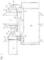
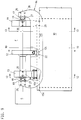
- All of the exemplary embodiments have in common that on a machine base 10 or a part thereof such as a swing frame 29 a stationary mold carrier 11 and a movable mold carrier 12 are arranged are.
- a Locking mechanism S provided on a support element 13 is arranged.
- the support element 13 is stationary Mold carrier movable over at least one power transmission element connected, which essentially with the closed mold 31st occurring closing and injection forces absorbs.
- the mobile Mold carrier 11 moves along a path of movement, preferably on guides 15, 22.
- the mold carriers have one between them Mold clamping space F for a casting mold 31 in FIG. 17. Both on stationary mold carrier 11 and on the movable mold carrier 12 Parts of the mold 31 can be determined.
- the power transmission element not only transmits the forces, but is a separate, deformable by the forces, Deformation element and in the exemplary embodiments as a bracket 14 educated.
- the bracket shape allows easy access to the Mold clamping space, but other shapes are also possible.
- the stationary Mold carrier 11 is on fasteners 23 on the machine base attached.
- all other parts of the Mold closing unit in particular movable mold carrier and Support element movable in relation to the machine base.
- the support element only on the rail 22 or the guide rail 15 is movably clawed and opposite Machine foot is movable along the closing direction. Become forces applied, so they have no influence on the machine base, because essentially only after derivation of the other deformations to an axial movement independent of the machine base in Closing direction comes.
- Deformation element 14 a decoupling of the deformations from the in Axial forces acting in the closing direction is possible. That’s it Deformation element freely suspended and with the support element 13 and the stationary mold carrier 11 articulated.
- the deformation element is formed by two C-shaped bracket 14, whereby the Injection opening E is kept clear.
- the linkage of the bracket on stationary mold carrier and the support element 13 is carried out Bearing elements.
- the bolt 17 is in a recess in the projection 11c stored, which passes through an eye 14d of the bracket 14.
- On the other Side is the bracket 14 via bolt 16 with the molding 13c as Support element trained cylinder plate connected, the Articulation point between the cylinder plate and the movable mold carrier 12 lies.
- FIGS. 9-15a In the third exemplary embodiment (FIGS. 9-15a), bolts 17 and 18 provided that as parts of a bearing by screws 25 on stationary mold carrier 11 or attached to the support member 13 are (Figs. 15, 16). The bolts are supported by a slide bearing 28 a bearing block 27 in connection with screws 26 on the bracket 14 is attached. This allows the forces to be released without torque transfer.
- bolts 17 and 18 are arranged that they are form-fitting between the stationary mold carrier 11 and bracket 14 or support member 13 and bracket 14 are added.
- the point of articulation in the area of the support element 13 is on the movable mold carrier 12 facing away from the support element arranged.
- Fig. 16 it can be seen that the bolts 17, 18 in Recesses 11a, 13a, 14a of the bracket 14, the stationary mold carrier 11 and the support element 13 are mounted. You will be perpendicular to passed through their axis by further bearing bolts 19 which in Bores 11b, 13b, 14b of bracket 14, stationary mold carrier 11 or Immerse the support element 13.
- the Bearing bolts 19 against the force of springs 20 in the bores 11b, 13b of stationary mold carrier and support element 13.
- This arrangement supports overcoming the demolding forces, but also leads to Frictional forces that make it difficult to decouple from the deformations.
- the Different arrangement options of the bracket create one Adaptability unmatched from the state of the art Customer requests e.g. with regard to different tool installation dimensions, if the bracket is articulated in front of or behind the support element.
- the Joint parts bolts 16, 17, 18 and bearing block 27 of the joints are through Screws on the articulated parts of the Closing unit releasably attached. If necessary, longer ones Screws 25 'in connection with washers 75 a change of the tool installation dimension allow between the joint parts and the adjacent components can be inserted (Fig. 15a).
- the mold clamping unit from the Arrangement of the bracket is independent of what its a variety of Possible uses.
- the mold clamping unit can be problem-free around a pivot pin 30 together with a pivot frame 29 in one vertical position are transferred (Fig. 16).
- Different from the Embodiments can also have several brackets at the same time be arranged inside, outside and / or on the machine base, to e.g. to be able to transmit greater forces.
- the movable one is Mold carriers on guides of the movement path on the machine base 10 guided.
- the first two exemplary embodiments are around two guide rails 15 which are arranged on the bearing 15a and on which the movable mold carrier 12 by sliding shoes 12a is secured against lifting.
- bracket 14 are still Guide rods 21 provided on the stationary mold carrier 11 and are supported on the support element 13. You are in one Space that is closed on both sides by the bracket 14, so that they do not represent an additional obstacle in the mold clamping area F.
- the movable mold carrier is supported by support elements 12c on a horizontal 22a and a vertical tread 22b of a rail 22 are guided on the machine base 10. In the third Embodiment is omitted on the guide rods 21.
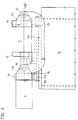
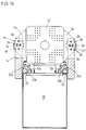
- FIGS. 17-24 acts as Closing mechanism a toggle mechanism with the articulation point 36 on the movable mold carrier 12 and with the articulation point 35 on a support element 13 '. He transfers the movable mold carrier into and out of the closed position.
- the toggle mechanism is called a "Y toggle lever" trained, i.e. its transverse to the closing direction s-s arranged drive device A is from the toggle lever mechanism Y over two holding elements 37, 38 held freely movable.
- the drive device becomes an electro-mechanical linear drive used in which a rotational movement in a straight-ahead movement is implemented.
- the toggle lever mechanism Y has two levers 42, 43, which are connected to one another via an articulation point 40. At this Joint point 40 also attacks a linear element of the linear drive.
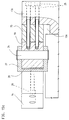
- the Ball screw can be arranged in a hollow shaft motor H, the is also the drive device A (Fig. 22).
- the hollow shaft motor H has a stator 52 and a rotor 51 in a housing 64 Rotor 51 is connected to a sleeve 53.
- the sleeve 53 carries coaxially co-operating with the ball screw 41 Threaded nut 54. With positive locking, the rotation of the Threaded nut the ball screw 41 into the sleeve or out. If necessary, it can be pulled down from the drive device an opening 64a of the housing emerge again.
- the the Holding elements 37, 38 carrying the drive device are on Articulation points 74, 75 connected to a connector part 55, which the actual drive device carries.
- the toggle mechanism Y is vertically movable and unlockable downwards.
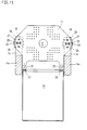
- the movable mold carrier 12 must be in connection with the only articulated toggle mechanism can be reliably guided.
- To it has a flat, plate-shaped and vertical part 12d and has two support parts 12e.
- the parts 12d, 12e of the Mold carrier 12 can be integrally formed or together be connected.
- the support members 12e extend both in one Area outside the mold clamping space F, as well as in the direction of the stationary mold carrier 11. This is the support surface and Area to accommodate tilting moments enlarged.
- the function of a The chute arranged in the area of the parting plane t-t is not impaired, since the support is only in the edge area, the already partially through the upper edge 10a of the Machine foot is claimed (Fig. 18).
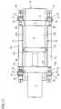
- the support parts 12e engage behind the guides on the Mold clamping space F opposite side and are on the guides over a central angle of at least 180 °. 19 are preferably in both support parts 12e as roller cassettes 32 trained running elements installed in a known manner horizontal and vertical treads 15b one as a guide trained, provided on the machine base 10 guide rail 15 are performed. Only one horizontal and two are conceivable to provide vertical roller cassettes.
- the support part 12e engages an arm 12e 'in the machine base under the guide rail. On the arm 12e 'a rear grip element 33 is arranged, which on a flanged upper edge 10a of the machine base 10 from below is present. Instead, built in the support parts 12e Ball bearing 34, the guide rods 21 designed as guides reach around. In both cases, the wrap takes on the forces that still occur who want to lift the movable mold carrier from the machine base, to record.
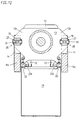
- the articulated arrangement of the "Y toggle lever” can also be advantageous in Be brought into connection with the deformation element.
- the stationary mold carrier 11 movable with at least one bracket 14 the support element 13 'connected.
- the "slipstream" of a leg 14c of the bracket 14 can guides for the support members 12e and for example, the bearings of the roller cassettes 32 in the Support elements 12c can be seen without a separate space must be claimed.
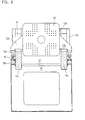
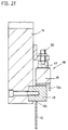
- the support element 13 ' is connected to the bracket 14 and the The bracket in turn can be designed as a bearing according to FIG. 21.
- the bearing element 46 is at an angle in the range of neutral fiber of the bracket 14 attached.
- a fine adjustment is over the adjusting element 50 possible, which is on a sliding element 49 is supported.
- the sliding element 49 takes over the actual Storage on the guide rail 15.
- the bearing elements 46 are in one in FIG plane v-v located perpendicular to the closing direction, the goes approximately through the articulation point 35. This situation was therefore chosen because this point is the hinge point for the deformation element is, so that the smallest deformations result here.
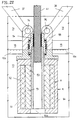
- a mold height adjustment V must be provided be a constant at different mold heights Position of the closing direction s-s allowed.
- a Spindle drive 39 is provided, which according to FIG. 18 on an abutment 44 is supported and via its threaded spindle 39a with the Support element 13 'is connected.
- the two spindle drives 39 can each be driven separately when setting up the machine be, so that there is an exact parallel setting between movable mold carrier 12 and stationary mold carrier 11 results.
- in the Both spindle drives are then in one operating state common drive 60 adjustable. Drives via a pulley 57 he two pulleys 56 for the threaded spindles over one or several straps 63 (Fig. 20). According to FIG. 18, this is the exact one Force application of disruptive thread play through disc springs 45 suppressed, which are held on a spacer 44a.
- threaded sleeves can also be provided via a second drive 62 are driven, which are designed as pulleys.
- the Threaded sleeve 62 is with its external thread on the spacer 44a in Thread engagement.
- the drive 60 can Pulley 56 are operated, which leads to an adjustment of the Lead screw 39a leads.
- the abutment 44 is the nut 71 of the Spindle drive held in a hole. After adjustment can by an opposite movement of the belt 65 of the second Drives the threaded sleeve 62 towards the spacer 44a are pressed so that the nut 71 via the threaded spindle 39a and the adjustment ring 73 is pressed.
- the threaded spindle 39a is on Support element 13 'added with play. The determination is made via Draw bolts 58 which engage a support ring 59. While dressing and thus adjusting the tension bolts, the threaded spindle 39a is countered the abutment 72 biased.
Landscapes
- Engineering & Computer Science (AREA)
- Mechanical Engineering (AREA)
- Manufacturing & Machinery (AREA)
- Injection Moulding Of Plastics Or The Like (AREA)
- Moulds For Moulding Plastics Or The Like (AREA)
Description
- Fig. 1
- eine Seitenansicht der Formschließeinheit der Spritzgießmaschine,
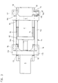
- Fig. 2
- einen Schnitt gemäß Linie 2-2 von Fig. 1,
- Fig. 3
- eine Draufsicht auf die Formschließeinheit gemäß Fig. 1,
- Fig. 4, 5
- Schnitte gemäß den Linien 4-4, 5-5 von Fig. 1,
- Fig. 6
- ein Verformungsbild der Spritzgießmaschine in einer Ansicht gemäß Fig. 1,
- Fig. 7, 8
- Darstellungen der Spritzgießmaschine in Ansichten gemäß Fig. 1, 2 eines weiteren Ausführungsbeispiels,
- Fig. 9-13
- Darstellungen einer dritten Ausführungsform in Ansichten gemäß den Fign. 1-5 mit einem veränderten Verformungselement,
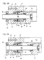
- Fig. 14,15
- Seitenansicht und teilweise geschnittene Draufsicht der gelenkigen Lagerung im dritten Ausführungsbeispiel,
- Fig. 15a
- eine Darstellung gemäß Fig. 15 mit einem Unterlegstück,
- Fig. 16
- die Spritzgießmaschine in einer Ansicht gemäß Fig. 1 in einer vierten Ausführungsform mit einem Schwenkrahmen,
- Fig. 17
- ein fünftes Ausführungsbeispiel der Formschließeinheit in einer Seitenansicht mit einem "Y-Kniehebel",
- Fig. 18
- eine Draufsicht auf die Formschließeinheit gemäß Fig. 17,
- Fig. 19
- einen Schnitt durch die Formschließeinheit gemäß Linie 19-19 von Fig. 17,
- Fig. 20
- einen Schnitt durch die Formschließeinheit gemäß Linie 20-20 von Fig. 17,
- Fig. 21
- einen vergrößerten Ausschnitt gemäß Linie 21-21 von Fig. 17 im Bereich der Lagerung,
- Fig. 22
- einen geschnittenen vergrößerten Ausschnitt aus Fig. 17 im Bereich eines Hohlwellenmotors,
- Fig. 23,24
- einen Schnitt durch die Formhöhenverstelleinrichtung von Fig. 17 im Bereich eines Spindelantriebs bei unterschiedlichen Formhöhen,
Claims (7)
- Spritzgießmaschine mit einem Maschinenfuß (10), einem mit dem Maschinenfuß oder einem Teil davon fest verbundenen, stationären (11) und einem beweglichen Formträger (12) sowie mit einem einen Schließmechanismus (S) für die Bewegung des beweglichen Formträgers (12) tragenden Abstützelement (13), das mit dem stationären Formträger (11) über wenigstens ein Kraftübertragungselement gelenkig verbunden ist, das im wesentlichen die bei geschlossener Gießform (31) auftretenden Kräfte aufnimmt, sowie mit einer Bewegungsbahn für den beweglichen Formträger (12),
dadurch gekennzeichnet, daß das Kraftübertragungselement als gesondertes, durch die Kräfte verformbares Verformungselement (14) ausgebildet ist, daß das Abstützelement (13) am Maschinenfuß (10) mittels einer Führung (15, 21, 21, 22) in Schließrichtung geradlinig beweglich gelagert ist, wobei Gelenkteile (16, 17, 18; 27) für die gelenkige Verbindung lösbar an Abstützelement (13) bzw. stationärem Formträger (11) und am Verformungselement (14) angeordnet sind. - Spritzgießmaschine nach Anspruch 1, dadurch gekennzeichnet, daß Bolzen (17, 18) mit Schrauben (25) am Abstützelement (13) und am stationären Formträger (11) lösbar befestigt sind und mit am als Bügel (14) ausgebildeten Verformungselement mittels Schrauben (26) lösbar befestigten Lagerböcken (27) Gelenke bilden.
- Spritzgießmaschine nach Anspruch 2, dadurch gekennzeichnet, daß der Bolzen (17, 18) in Ausnehmungen (11a,13a,14a) des Bügels (14) und des stationären Formträgers (11) oder des Abstützelements (13) gelagert ist und von senkrecht zur Bolzenachse stehenden weiteren Lagerbolzen (19) durchgriffen ist, die in Bohrungen (11b,13b,14b) von Bügel (14) und stationärem Formträger (11) oder Abstützelement (13) eintauchen.
- Spritzgießmaschine nach einem der vorhergehenden Ansprüche, dadurch gekennzeichnet, daß der Abstand zwischen stationärem (11) und beweglichem Formträger (12) durch Unterlegstücke (75) veränderbar ist, die zwischen Gelenkteilen und staionärem Formträger (11), Abstützelement (13) und/oder Verformungselement einfügbar sind.
- Spritzgießmaschine nach einem der vorhergehenden Ansprüche, dadurch gekennzeichnet, daß der Schließmechanismus ein Kniehebelmechanismus (Y) ist und daß ein Verbindungselement (55) über zwei an Anlenkungspunkten (35, 36) des Kniehebelmechanismus (Y) am beweglichen Formträger (12) und an dem Abstützelement (13') angelenkte Halteelemente (37, 38) gelenkig aufgehängt ist, an dem die Antriebseinrichtung (A) befestigt ist.
- Spritzgießmaschine nach Anspruch 5, dadurch gekennzeichnet, daß die Antriebseinrichtung als Hohlwellenmotor (H) ausgebildet ist, in dem eine als Antriebselement ausgebildete Kugelrollspindel (41) gelagert und zumindest teilweise aufnehmbar ist.
- Spritzgießmaschine nach Anspruch 5 oder 6, dadurch gekennzeichnet, daß der Bügel (14) das Abstützelement (13') am Maschinenfuß (10) im Bereich der neutralen Faser des Bügels (14) über Lagerelemente (46) in Schließrichtung (s-s) beweglich lagert, die in einer senkrecht zur Schließrichtung gelegenen Ebene (v-v) angeordnet sind, die ungefähr durch den Anlenkungspunkt (35) des Kniehebelmechanismus (Y) gelegt ist.
Applications Claiming Priority (6)
| Application Number | Priority Date | Filing Date | Title |
|---|---|---|---|
| DE19934308962 DE4308962C2 (de) | 1993-03-20 | 1993-03-20 | Formschließeinheit für eine Spritzgießmaschine |
| DE4308962 | 1993-03-20 | ||
| DE4313473A DE4313473C2 (de) | 1993-03-20 | 1993-04-24 | Schließeinheit für eine Spritzgießmaschine |
| DE4313473 | 1993-04-24 | ||
| DE4323395 | 1993-07-13 | ||
| DE19934323395 DE4323395C2 (de) | 1993-07-13 | 1993-07-13 | Schließeinheit für eine Kunststoff-Spritzgießmaschine |
Publications (3)
| Publication Number | Publication Date |
|---|---|
| EP0620095A2 EP0620095A2 (de) | 1994-10-19 |
| EP0620095A3 EP0620095A3 (de) | 1995-01-04 |
| EP0620095B1 true EP0620095B1 (de) | 1999-01-07 |
Family
ID=27204880
Family Applications (1)
| Application Number | Title | Priority Date | Filing Date |
|---|---|---|---|
| EP93115689A Expired - Lifetime EP0620095B1 (de) | 1993-03-20 | 1993-09-29 | Spritzgiessmaschine |
Country Status (3)
| Country | Link |
|---|---|
| EP (1) | EP0620095B1 (de) |
| AT (1) | ATE175380T1 (de) |
| DE (1) | DE59309279D1 (de) |
Cited By (1)
| Publication number | Priority date | Publication date | Assignee | Title |
|---|---|---|---|---|
| DE102006061969B4 (de) * | 2006-12-21 | 2009-12-17 | Karl Hehl | Verfahren zum Betreiben einer Spritzgießmaschine mit zwei Kniehebelmechanismen |
Families Citing this family (10)
| Publication number | Priority date | Publication date | Assignee | Title |
|---|---|---|---|---|
| ATE185312T1 (de) * | 1993-09-30 | 1999-10-15 | Karl Hehl | Spritzgiessmaschine zur verarbeitung von plastifizierbaren massen |
| DE59505912D1 (de) * | 1994-12-20 | 1999-06-17 | Krauss Maffei Ag | Formschliessvorrichtung für eine kunststofformmaschine, insbesondere eine spritzgiessmaschine |
| BR9800139C1 (pt) * | 1998-03-23 | 2000-03-14 | Ind Romi S A Ind Romi S A | Desenvolvimento em mecanismo de bloqueio de molde |
| DE50201729D1 (de) | 2001-02-15 | 2005-01-13 | Mannesmann Plastics Machinery | Schliesseinrichtung in einer spritzgiessmaschine für kunststoffe |
| AT511653B1 (de) * | 2011-06-15 | 2014-08-15 | Smc Pneumatik Ges M B H | Vorrichtung zum anheben und fixieren |
| JP6889379B2 (ja) * | 2016-03-31 | 2021-06-18 | キョーラク株式会社 | 型締め装置 |
| DE112021002107T5 (de) * | 2020-03-31 | 2023-01-19 | Sumitomo Heavy Industries, Ltd. | Basisrahmen für spritzgiessmaschine |
| CN112776255B (zh) * | 2020-12-30 | 2024-12-13 | 无锡超通智能制造技术研究院有限公司 | 基于机器人的风扇注塑模具自动上下料抓手 |
| CN113183403B (zh) * | 2021-05-20 | 2024-10-25 | 佛山市宝捷精密机械有限公司 | 一种注塑机射台自适应支撑机构 |
| CN120307543A (zh) * | 2025-04-29 | 2025-07-15 | 惠州东铭新能源材料股份有限公司 | 一种用于聚氨酯产品浇注的全自动环形回流生产设备 |
Family Cites Families (12)
| Publication number | Priority date | Publication date | Assignee | Title |
|---|---|---|---|---|
| US2266129A (en) * | 1938-11-05 | 1941-12-16 | Sterling Injection Molding Inc | Thermoplastic molding machine |
| DE1116386B (de) * | 1958-06-07 | 1961-11-02 | Arburg Feingeraete Fabrik O H | Hydraulische oder pneumatische Antriebsvorrichtung zur Betaetigung einer Formschliesseinheit fuer thermoplastische Kunststoffe verarbeitende Spritzgussmaschinen |
| US3577596A (en) * | 1968-06-26 | 1971-05-04 | Vigeant Gaston | Two-phase mold press |
| US3704973A (en) * | 1971-06-08 | 1972-12-05 | Husky Mfg & Toolworks Ltd | Electro-hydraulic means for opening and closing injection molds |
| DE3145973C1 (de) * | 1981-11-20 | 1983-05-19 | Karl 7298 Loßburg Hehl | Kunststoff-Spritzgiessmaschine mit auf Fuehrungsschienen gelagerter Formschliesseinheit |
| JP2673814B2 (ja) * | 1988-04-06 | 1997-11-05 | ファナック株式会社 | 射出成形機の形締装置 |
| CH680916A5 (de) * | 1989-11-10 | 1992-12-15 | Vickers Inc | |
| EP0504580A3 (en) * | 1991-03-20 | 1993-02-03 | H.A. Schlatter Ag | Press device and flash butt-welding machine equipped with such a device |
| AT397228B (de) * | 1991-09-12 | 1994-02-25 | Engel Gmbh Maschbau | Spritzgiessmaschine |
| AT398290B (de) * | 1991-09-18 | 1994-11-25 | Engel Gmbh Maschbau | Spritzgiessmaschine |
| DE4141259C2 (de) * | 1991-12-14 | 1993-10-07 | Hemscheidt Maschtech Schwerin | Formschließeinrichtung für Spritzgießmaschinen |
| IL100832A (en) * | 1992-01-31 | 1994-01-25 | Ziv Av Amir | Clamping assembly for an injection moulding apparatus |
-
1993
- 1993-09-29 DE DE59309279T patent/DE59309279D1/de not_active Expired - Fee Related
- 1993-09-29 EP EP93115689A patent/EP0620095B1/de not_active Expired - Lifetime
- 1993-09-29 AT AT93115689T patent/ATE175380T1/de active
Cited By (1)
| Publication number | Priority date | Publication date | Assignee | Title |
|---|---|---|---|---|
| DE102006061969B4 (de) * | 2006-12-21 | 2009-12-17 | Karl Hehl | Verfahren zum Betreiben einer Spritzgießmaschine mit zwei Kniehebelmechanismen |
Also Published As
| Publication number | Publication date |
|---|---|
| EP0620095A2 (de) | 1994-10-19 |
| ATE175380T1 (de) | 1999-01-15 |
| EP0620095A3 (de) | 1995-01-04 |
| DE59309279D1 (de) | 1999-02-18 |
Similar Documents
| Publication | Publication Date | Title |
|---|---|---|
| EP0311133B2 (de) | Spritzgiessmaschine | |
| DE69009203T2 (de) | Formschliessvorrichtung für eine Giessmaschine. | |
| EP0722820B1 (de) | Holmlose Formschliesseinrichtung | |
| AT402811B (de) | Spritzgiessmaschine | |
| EP0300223A2 (de) | Schliessvorrichtung für Formen zum Herstellen von Gegenständen aus thermoplastischem Kunststoff | |
| EP0668817A1 (de) | Spritzgiessmaschine | |
| DE4313473C2 (de) | Schließeinheit für eine Spritzgießmaschine | |
| DE602004007562T2 (de) | Spannvorrichtung für eine Spritzgiessmaschine | |
| EP0620095B1 (de) | Spritzgiessmaschine | |
| EP0626245B1 (de) | Formschliesseinheit für eine Kunststoff-Spritzgiessmaschine | |
| EP0646448B1 (de) | Spritzgiessmaschine zur Verarbeitung von plastifizierbaren Massen | |
| EP0687541B1 (de) | Holmlose Formschliesseinrichtung für Spritzgiessmaschinen | |
| DE69805747T2 (de) | Spannvorrichtung für eine holmlose Spritzgiessmaschine | |
| EP0631857B1 (de) | Kunststoff-Spritzgiessmaschine mit einer Formschliesseinheit | |
| WO1996019331A1 (de) | Formschliessvorrichtung für eine kunststofformmaschine, insbesondere eine spritzgiessmaschine | |
| EP0754534B1 (de) | Einrichtung zum Spritzgiessen von Kunststoff | |
| EP0933181A2 (de) | Schliessvorrichtung für Formen zum Herstellen von Gegenständen aus thermoplastischem Kunststoff | |
| EP1802441B1 (de) | Schliesseinheit für eine spritzgiessmaschine mit etagenwerkzeug | |
| EP0835733A1 (de) | Spritzgiessmaschine mit einer Werkzeugschliesseinrichtung | |
| EP1487626B1 (de) | Formschliesseinheit mit einer formhöhenverstellung sowie verfahren zu deren betätigung | |
| DE4308962C2 (de) | Formschließeinheit für eine Spritzgießmaschine | |
| DE4411649C2 (de) | Schließeinheit für Formen zum Herstellen von Gegenständen aus plastifizierbaren Massen | |
| EP1848577B1 (de) | Spritzgiessmaschine zur verarbeitung von kunststoffen | |
| DE4320366A1 (de) | Kunststoff-Spritzgießmaschine mit einer Formschließeinheit | |
| AT400022B (de) | Spritzgiessmaschinen |
Legal Events
| Date | Code | Title | Description |
|---|---|---|---|
| PUAI | Public reference made under article 153(3) epc to a published international application that has entered the european phase |
Free format text: ORIGINAL CODE: 0009012 |
|
| 17P | Request for examination filed |
Effective date: 19930929 |
|
| AK | Designated contracting states |
Kind code of ref document: A2 Designated state(s): AT CH DE ES FR GB IT LI NL |
|
| PUAL | Search report despatched |
Free format text: ORIGINAL CODE: 0009013 |
|
| AK | Designated contracting states |
Kind code of ref document: A3 Designated state(s): AT CH DE ES FR GB IT LI NL |
|
| 17Q | First examination report despatched |
Effective date: 19970304 |
|
| GRAG | Despatch of communication of intention to grant |
Free format text: ORIGINAL CODE: EPIDOS AGRA |
|
| GRAG | Despatch of communication of intention to grant |
Free format text: ORIGINAL CODE: EPIDOS AGRA |
|
| GRAH | Despatch of communication of intention to grant a patent |
Free format text: ORIGINAL CODE: EPIDOS IGRA |
|
| GRAH | Despatch of communication of intention to grant a patent |
Free format text: ORIGINAL CODE: EPIDOS IGRA |
|
| GRAA | (expected) grant |
Free format text: ORIGINAL CODE: 0009210 |
|
| AK | Designated contracting states |
Kind code of ref document: B1 Designated state(s): AT CH DE ES FR GB IT LI NL |
|
| PG25 | Lapsed in a contracting state [announced via postgrant information from national office to epo] |
Ref country code: NL Free format text: LAPSE BECAUSE OF FAILURE TO SUBMIT A TRANSLATION OF THE DESCRIPTION OR TO PAY THE FEE WITHIN THE PRESCRIBED TIME-LIMIT Effective date: 19990107 Ref country code: ES Free format text: THE PATENT HAS BEEN ANNULLED BY A DECISION OF A NATIONAL AUTHORITY Effective date: 19990107 |
|
| REF | Corresponds to: |
Ref document number: 175380 Country of ref document: AT Date of ref document: 19990115 Kind code of ref document: T |
|
| REG | Reference to a national code |
Ref country code: CH Ref legal event code: EP |
|
| REF | Corresponds to: |
Ref document number: 59309279 Country of ref document: DE Date of ref document: 19990218 |
|
| REG | Reference to a national code |
Ref country code: CH Ref legal event code: NV Representative=s name: LUCHS & PARTNER PATENTANWAELTE |
|
| GBT | Gb: translation of ep patent filed (gb section 77(6)(a)/1977) |
Effective date: 19990210 |
|
| ET | Fr: translation filed | ||
| ITF | It: translation for a ep patent filed | ||
| NLV1 | Nl: lapsed or annulled due to failure to fulfill the requirements of art. 29p and 29m of the patents act | ||
| PGFP | Annual fee paid to national office [announced via postgrant information from national office to epo] |
Ref country code: GB Payment date: 19990913 Year of fee payment: 7 |
|
| PGFP | Annual fee paid to national office [announced via postgrant information from national office to epo] |
Ref country code: FR Payment date: 19990917 Year of fee payment: 7 |
|
| PGFP | Annual fee paid to national office [announced via postgrant information from national office to epo] |
Ref country code: CH Payment date: 19990921 Year of fee payment: 7 Ref country code: AT Payment date: 19990921 Year of fee payment: 7 |
|
| PLBE | No opposition filed within time limit |
Free format text: ORIGINAL CODE: 0009261 |
|
| STAA | Information on the status of an ep patent application or granted ep patent |
Free format text: STATUS: NO OPPOSITION FILED WITHIN TIME LIMIT |
|
| 26N | No opposition filed | ||
| PG25 | Lapsed in a contracting state [announced via postgrant information from national office to epo] |
Ref country code: GB Free format text: LAPSE BECAUSE OF NON-PAYMENT OF DUE FEES Effective date: 20000929 Ref country code: AT Free format text: LAPSE BECAUSE OF NON-PAYMENT OF DUE FEES Effective date: 20000929 |
|
| PG25 | Lapsed in a contracting state [announced via postgrant information from national office to epo] |
Ref country code: LI Free format text: LAPSE BECAUSE OF NON-PAYMENT OF DUE FEES Effective date: 20000930 Ref country code: CH Free format text: LAPSE BECAUSE OF NON-PAYMENT OF DUE FEES Effective date: 20000930 |
|
| REG | Reference to a national code |
Ref country code: CH Ref legal event code: PL |
|
| GBPC | Gb: european patent ceased through non-payment of renewal fee |
Effective date: 20000929 |
|
| PG25 | Lapsed in a contracting state [announced via postgrant information from national office to epo] |
Ref country code: FR Free format text: LAPSE BECAUSE OF NON-PAYMENT OF DUE FEES Effective date: 20010531 |
|
| REG | Reference to a national code |
Ref country code: FR Ref legal event code: ST |
|
| PGFP | Annual fee paid to national office [announced via postgrant information from national office to epo] |
Ref country code: DE Payment date: 20030830 Year of fee payment: 11 |
|
| PG25 | Lapsed in a contracting state [announced via postgrant information from national office to epo] |
Ref country code: DE Free format text: LAPSE BECAUSE OF NON-PAYMENT OF DUE FEES Effective date: 20050401 |
|
| PG25 | Lapsed in a contracting state [announced via postgrant information from national office to epo] |
Ref country code: IT Free format text: LAPSE BECAUSE OF NON-PAYMENT OF DUE FEES;WARNING: LAPSES OF ITALIAN PATENTS WITH EFFECTIVE DATE BEFORE 2007 MAY HAVE OCCURRED AT ANY TIME BEFORE 2007. THE CORRECT EFFECTIVE DATE MAY BE DIFFERENT FROM THE ONE RECORDED. Effective date: 20050929 |