EP0475462A1 - Method for using a drum washing machine and washing machine to perform this method - Google Patents
Method for using a drum washing machine and washing machine to perform this method Download PDFInfo
- Publication number
- EP0475462A1 EP0475462A1 EP19910118837 EP91118837A EP0475462A1 EP 0475462 A1 EP0475462 A1 EP 0475462A1 EP 19910118837 EP19910118837 EP 19910118837 EP 91118837 A EP91118837 A EP 91118837A EP 0475462 A1 EP0475462 A1 EP 0475462A1
- Authority
- EP
- European Patent Office
- Prior art keywords
- drum
- section
- during
- rotation
- washing
- Prior art date
- Legal status (The legal status is an assumption and is not a legal conclusion. Google has not performed a legal analysis and makes no representation as to the accuracy of the status listed.)
- Granted
Links
Images


Classifications
-
- D—TEXTILES; PAPER
- D06—TREATMENT OF TEXTILES OR THE LIKE; LAUNDERING; FLEXIBLE MATERIALS NOT OTHERWISE PROVIDED FOR
- D06F—LAUNDERING, DRYING, IRONING, PRESSING OR FOLDING TEXTILE ARTICLES
- D06F37/00—Details specific to washing machines covered by groups D06F21/00 - D06F25/00
- D06F37/02—Rotary receptacles, e.g. drums
- D06F37/04—Rotary receptacles, e.g. drums adapted for rotation or oscillation about a horizontal or inclined axis
- D06F37/06—Ribs, lifters, or rubbing means forming part of the receptacle
- D06F37/065—Ribs, lifters, or rubbing means forming part of the receptacle ribs or lifters having means for circulating the washing liquid
-
- D—TEXTILES; PAPER
- D06—TREATMENT OF TEXTILES OR THE LIKE; LAUNDERING; FLEXIBLE MATERIALS NOT OTHERWISE PROVIDED FOR
- D06F—LAUNDERING, DRYING, IRONING, PRESSING OR FOLDING TEXTILE ARTICLES
- D06F35/00—Washing machines, apparatus, or methods not otherwise provided for
- D06F35/005—Methods for washing, rinsing or spin-drying
- D06F35/006—Methods for washing, rinsing or spin-drying for washing or rinsing only
-
- Y—GENERAL TAGGING OF NEW TECHNOLOGICAL DEVELOPMENTS; GENERAL TAGGING OF CROSS-SECTIONAL TECHNOLOGIES SPANNING OVER SEVERAL SECTIONS OF THE IPC; TECHNICAL SUBJECTS COVERED BY FORMER USPC CROSS-REFERENCE ART COLLECTIONS [XRACs] AND DIGESTS
- Y02—TECHNOLOGIES OR APPLICATIONS FOR MITIGATION OR ADAPTATION AGAINST CLIMATE CHANGE
- Y02B—CLIMATE CHANGE MITIGATION TECHNOLOGIES RELATED TO BUILDINGS, e.g. HOUSING, HOUSE APPLIANCES OR RELATED END-USER APPLICATIONS
- Y02B40/00—Technologies aiming at improving the efficiency of home appliances, e.g. induction cooking or efficient technologies for refrigerators, freezers or dish washers
Definitions
- the invention relates to a method for operating a drum washing machine and a drum washing machine therefor with a horizontally rotatably mounted washing drum with a perforated drum jacket and with drivers arranged therein, which have scooping devices that are open towards the interior thereof, and with an automatically controlled washing program that has a wetting section with a drum speed of at most 30 min- 1 , a rinse section with a drum speed of at most 60 min- 1 , a rinse section and a spin section.
- Such a drum washing machine is known from DE-OS 37 12 118. It is operated continuously in a wetting phase, preferably at a laundry drum speed of 27 min- 1 . Compared to drum washing machines, the drum of which is also operated during the wetting phase at the usual washing speed of 55 min- 1 , for example, the wetting of the laundry can be intensified to such a degree that even with the lowest possible water level just above the lower apex of the laundry drum in a relatively short time Time is moistened homogeneously.
- drum washing machines on the market are already provided with a hidden device for increasing the water level.
- the originally intended saving effect in relation to the amount of water and energy used is given up again.
- the invention is therefore based on the object of operating a drum washing machine of the known type in such a way that the laundry is homogeneously wetted with absolute certainty and in the shortest possible time even at a very low water level and is more effectively freed from dirt during the rinse section.
- the object is achieved in that the drum is driven intermittently during the wetting section with at most 30%, preferably 25%, duty cycle and only in the scooping direction during the rinsing section and during the rinsing section alternately in the scooping direction and in the emptying direction and during the spinning section only in the emptying direction.
- the irrigation effect described in DE-OS 37 12 118 is responsible for the homogeneous moistening of the laundry, but that during washing pauses between the drum rotation intervals, the lye rained on the laundry during a seeping process Can wet laundry even more intensely.
- the dirt detaching effect is increased during the clear wash section, as will be explained further below.
- the drum is driven alternately in the direction of scooping and in the direction of emptying during the wetting section.
- the change in the drum rotation direction creates a pumping effect of the alkali within the suds container and the laundry drum and such a shifting of the Laundry that during the subsequent scooping and sprinkling process again dry laundry parts are exposed to the lye rain.
- a further development of the method according to the invention prefers the duty cycle during an interval of the drum drive with approximately 4 s and the downtime of the drum with approximately 12 s. 4 s running time of the drum convey enough lye over the laundry, which is seeped out by the lye during 12 s drum standstill.
- a further development of the method is particularly advantageous, in which the drum drive is switched on during the wetting section for the first time after a lye level has been reached at which the scooping devices are immersed in the lye. This can prevent the laundry that has not yet been wetted from being layered dry in the laundry for too long and thereby being subject to increased abrasion.
- the wetting section of the method according to the invention is advantageously a maximum of 3 minutes long.
- a full laundry load of, for example, 4.5 kg can be moistened homogeneously within this time.
- the drum is also intermittently during the wetting section with a maximum of 30%, preferably 25% duty cycle and only alternately in the scooping direction during the clear washing section and during the rinsing section alternately in the scooping direction and in the emptying direction as well only driven in the direction of emptying during the spinning section, but the rinse section has at least two cycles, which comprises a washer-extracting phase in which the washing drum is rotated in the emptying direction of rotation at a speed of up to 300 min- 1 , and a reversing phase in which the washing drum alternates with a washing speed of un is rotated approximately 55 min- 1 , the direction of scoop being maintained for less than the direction of emptying.
- a special washing effect can be achieved in such a way, that the alkali level in the suds container outside the laundry drum is increased during the spin cycle by expelling the alkali from the laundry, while in the subsequent reversing phase almost the whole Lye amount is taken up again in the laundry drum and in the laundry, so that an almost complete exchange of the washing liquor bound by the laundry takes place.
- This exchange also means that dispersed and bound dirt particles are driven out of the laundry more intensively.
- the scooping devices of all drivers can point in a common scooping direction. This simplifies the construction of the laundry drum and is particularly well suited if all the desired wetting and washing effects can be achieved by less complex control means.
- each driver contains at least two mutually sealed chambers of different volumes and point their associated scooping devices in different scooping directions. As a result, a variety of wetting and washing effects can be achieved using a few different rotation rhythms.
- the washer-extractor phase of a drum washing machine according to the method of claim 5 advantageously lasts about 10 s, while the reversing phase takes about 80 s.
- the effect described above can be optimized by the fact that the duration of the scoop rotation direction and the duration of the emptying rotation direction within a reversing phase are approximately 1: 3.
- a special design of the drum washing machine according to the invention results from the design of the drivers in the form of a saddle roof, the roof surface on the side of the scoop being unperforated, the other roof surface being perforated in the area of the roof top and unperforated in the area of the roof base.
- Such a form of the carrier has proven to be particularly well suited for the scooping action and the sprinkling of the laundry.
- the tub 1 in FIG. 1 contains in its upper area a filling opening 2 for detergent introduced from a detergent dispenser 3 together with feed water.
- the bottom of the lye container 1, which is kept as close as possible to the drum 4, has a recess 5 in which the heating elements 6 required for heating the lye are arranged.
- a recess 5 At the deepest point of the recess 5 there is an outlet opening 7 which is kept closed by a closure body 8 as long as a drain pump (not shown) does not suck on the drain line 9.
- This closure body 8 has the task of keeping the space below the drain opening 7 closed as long as there is detergent required for washing the laundry inside the tub.
- the drum washing machine known from DE-OS 37 12 118 therefore has scooping devices 12 on the circumference in the area of the drivers 11, which when rotating the drum, e.g. in the direction of arrow 13, from the lye stock standing in the recess 5, the respective intermediate storage space, here the driver 11, can fill.
- this scooped amount of water is first temporarily stored and only released into the drum interior via outlet openings in the intermediate storage space when the intermediate storage space is a certain height in the region below or above the horizontal drum axis 15, but preferably above that lying in the drum 4, completely wetted laundry 10 has reached.
- the arrows 14 indicate the manner in which the water so raised rains over the laundry 10.
- the driver 11 can be divided into bulkheads 23 by bulkheads 23 according to FIG. 2. Here they are similar to the drivers in Fig. 6 of DE-OS 37 12 118.
- the chambers 25 distributed along the driver in turn, like the known driver, have alternating ladles 20 pointing in one and in the other direction of rotation as scooping devices for the drivers.
- the roof-shaped part of the driver only has flood holes 17 on the roof surface opposite the ladle 20, through which raised lye can be rinsed.
- the flood holes are arranged in each of these roof areas, but only in the vicinity of the roof top, so that sufficient lye can accumulate in the solid angle at the foot of this roof area for lifting up.
- the right ladle scoops 20 lye into the chamber 25.
- Fig. 4 shows a driver with only a single chamber 41, the scoops of which are directed in one direction only. Accordingly, this chamber can only scoop in one direction of rotation.
- the scoops 20 facing away from the respective direction of rotation and the associated chambers of all exemplary embodiments of drivers pump lye out of the laundry drum again and convey it into the space between the drum and the tub. This promotes the exchange between the lye in the laundry and the free lye. This results in a better washing effect because dirt detached from the laundry can be washed out of the laundry more quickly.
- the laundry drum shown in FIG. 5 rotates in the direction of scooping according to arrow 13.
- the scoops 20 scoop the lye from the tub into the driver 11 and, on the other hand, the flood holes 16 also from the space between the drum 4 and the tub of liquor onto the unperforated roof surfaces 26 of the drivers 11.
- the driver located further up shows that lye drawn according to the arrow 18 flows from the outside of the roof surface 26 onto the laundry lying below (not shown in FIGS. 5 and 6) and shortly thereafter also drawn lye through the flood holes 17 according to the arrows 14 from the driver 11 onto the Laundry is raining. It can therefore be seen from this that the wetting effect is greater than in the subject of DE-OS 37 12 118.
- the laundry drum shown in FIG. 6 rotates according to arrow 19 in the direction of emptying.
- This lye essentially comes from the wet laundry according to arrow 21 and is also sucked through the flood holes 16 in the drum jacket from the space between the drum and the tub at drum speeds of up to about 60 min- 1 .
- the centrifugal force predominates, so that moisture is only sucked in from the inside of the drum.
- the laundry drum is driven at intervals with a maximum of 30% duty cycle.
- Laundry drums the drivers of which are designed according to FIGS. 2 and 3, can be driven reversing.
- the reversing rhythm can also be distributed uniformly, e.g. 3 s anticlockwise rotation, 9 s pause, 3 s clockwise rotation and 9 s pause. This results in a total of 24 s for an interval and 25% duty cycle.
- the reversing rhythm can be inversely distributed so that the same amount of irrigation is added to the laundry with every scoop, e.g. 3 s counter-clockwise rotation, 14 s pause, 9 s clockwise rotation, 14 s pause. This results in a total of 40 s for an interval and 30% duty cycle.
- Laundry drums the drivers of which only have a chamber 41 with a ladle 20 acting in one direction of rotation according to FIG. 4, are expediently operated in the wetting section only in this one direction of rotation.
- the washing drum can run for 5 s and stand for 15 s in every interval, which is a duty cycle of 25%.
- the rainy liquor slowly seeps through the laundry in the direction of gravity before the laundry is shifted again in the subsequent running phase.
- the laundry drum is driven differently than in the wetting section. Since it is no longer a question of optimal wetting, but of an optimal mechanical treatment of the laundry, the laundry drum is driven at a normal drum speed during the rinse cycle section - except for the treatment of delicate laundry such as wool, for example 55 min- 1.
- wash-spin phases WSP and reverse phases RP can be subdivided into wash-spin phases WSP and reverse phases RP.
- the washing drum is accelerated in the discharge direction from a standstill, until it reaches, for example, a speed of 300 min-. 1 This process takes about 10 seconds.
- the spin start can also be limited in time; then the final speed reached is determined by the loading of the laundry drum. It may vary between 150 min- 1 and 350 min- 1 .
- a wash-spin phase WSP is followed by a reversing phase RP in the clear wash section, during which the drum is driven in reversing mode.
- RP reversing phase
- This reversing phase lasts for example 80 s.
- the ratio of the volume of the respective chambers in the drivers and, on the other hand, the distribution of the drum operation over the respective directions of rotation are decisive for this ratio of the amount of lye emptied and emptied.
- a driver design according to FIG. 2 fails for this application; because this driver would draw the same amount of lye in both directions of rotation. Therefore, we only consider the drivers according to FIGS. 3 and 4.
- E means the drum operation in the emptying direction of rotation and S the drum operation in the scooping direction of rotation (in FIG. 3 in each case related to the larger chamber 32).
- the intensive aisle for drivers according to FIG. 3 is divided into 8 s emptying rotation direction, 3 s standstill, 6 s scooping rotation direction and again 3 s stoppage, for drivers according to FIG. 4 in 12 s emptying rotation direction, 3 s standing still, 2 s scooping rotation direction and 3 s standstill.
- the normal gear according to FIG. 9 for drivers according to FIG. 3 shows 6 s emptying direction of rotation, 5 s standstill, 4 s scooping direction of rotation and 5 s standstill or for drivers according to FIG. 4 8.5 s emptying direction of rotation, 5 s standstill, 1.5 s scoop direction of rotation and 5 s standstill and the inlet according to FIG. 10 for drivers according to FIG. 3 3.5 s emptying direction of rotation, 7 s standstill, 2.5 s scoop direction of rotation and 7 s standstill or for drivers according to FIG. 4 5 s emptying direction of rotation, 7 s standstill, 1 s scoop direction of rotation and 7 s standstill.
- the symmetrical distribution of downtimes after each run can also be abandoned. For example, it may be advantageous if the downtimes after each run in the scoop direction of rotation are longer than after the emptying direction of rotation, so that the lye has a longer opportunity to dribble through the laundry.
- the rinsing section is also held with a reversed drum operation, which is set so that, similar to FIG. 7, the level in the tub rises and falls counter-cyclically to the amount of tubing in the laundry.
- the proportion of the drum drive in the scoop rotation direction can be larger than in the discharge rotation direction.
- the proportions of the respective drum directions of rotation will be measured. As a result, the rinse water flow through the laundry is intensified and the lye residues are better rinsed out. Otherwise, the findings from the clear wash section described above can be taken into account.
Abstract
Description
Die Erfindung betrifft ein Verfahren zum Betreiben einer Trommelwaschmaschine und eine Trommelwaschmaschine dafür mit einer horizontal drehbar gelagerten Wäschetrommel mit gelochtem Trommelmantel und mit darin angeordneten Mitnehmern, die zu ihrem Innenraum hin offene Schöpfvorrichtungen aufweisen, und mit einem automatisch gesteuerten Waschprogramm, das einen Benetzungsabschnitt mit einer Trommeldrehzahl von höchstens 30 min-1, einen Klarwäscheabschnitt mit einer Trommeldrehzahl von höchstens 60 min-1, einen Spülabschnitt und einen Schleuderabschnitt aufweist.The invention relates to a method for operating a drum washing machine and a drum washing machine therefor with a horizontally rotatably mounted washing drum with a perforated drum jacket and with drivers arranged therein, which have scooping devices that are open towards the interior thereof, and with an automatically controlled washing program that has a wetting section with a drum speed of at most 30 min- 1 , a rinse section with a drum speed of at most 60 min- 1 , a rinse section and a spin section.
Eine solche Trommelwaschmaschine ist aus der DE-OS 37 12 118 bekannt. Sie wird in einer Benetzungsphase vorzugsweise mit einer Wäschetrommel-Drehzahl von 27 min-1 kontinuierlich betrieben. Dadurch konnte gegenüber Trommelwaschmaschinen, deren Trommel auch während der Benetzungsphase mit der üblichen Waschdrehzahl von beispielsweise 55 min-1 betrieben wird, die Benetzung der Wäsche so stark intensiviert werden, daß die Wäsche auch bei geringstmöglichem Wasserstand kurz oberhalb des unteren Scheitelpunktes der Wäschetrommel in verhältnismäßig kurzer Zeit homogen durchfeuchtet ist.Such a drum washing machine is known from DE-OS 37 12 118. It is operated continuously in a wetting phase, preferably at a laundry drum speed of 27 min- 1 . Compared to drum washing machines, the drum of which is also operated during the wetting phase at the usual washing speed of 55 min- 1 , for example, the wetting of the laundry can be intensified to such a degree that even with the lowest possible water level just above the lower apex of the laundry drum in a relatively short time Time is moistened homogeneously.
Offenbar scheinen Fachleute jedoch mit den Benetzungs- und Reinigungsergebnissen der Wäsche in Trommelwaschmaschinen nicht uneingeschränkt zufrieden zu sein, so daß am Markt befindliche Trommelwaschmaschinen bereits mit einer versteckt angeordneten Einrichtung zum Erhöhen des Wasserstandes versehen ist. Hierdurch wird jedoch der ursprünglich angestrebte Spareffekt in Bezug auf die eingesetzte Wasser- und Energiemenge wieder aufgegeben.Apparently, however, experts do not seem to be fully satisfied with the wetting and cleaning results of the laundry in drum washing machines, so that drum washing machines on the market are already provided with a hidden device for increasing the water level. As a result, however, the originally intended saving effect in relation to the amount of water and energy used is given up again.
Der Erfindung liegt daher die Aufgabe zugrunde, eine Trommelwaschmaschine der bekannten Art derart zu betreiben, daß die Wäsche auch bei sehr geringem Wasserstand mit absoluter Sicherheit und in kürzester Zeit homogen benetzt und während des Klarwäscheabschnitts effektiver vom Schmutz befreit wird.The invention is therefore based on the object of operating a drum washing machine of the known type in such a way that the laundry is homogeneously wetted with absolute certainty and in the shortest possible time even at a very low water level and is more effectively freed from dirt during the rinse section.
Die Aufgabe wird dadurch gelöst, daß die Trommel während des Benetzungsabschnitts mit höchstens 30 %, vorzugsweise 25 %, Einschaltdauer intervallartig und nur in Schöpfrichtung während des Klarwäscheabschnitts und während des Spülabschnitts abwechselnd in Schöpfdrehrichtung und in Entleerungsdrehrichtung sowie während des Schleuderabschnitts nur in Entleerungsdrehrichtung angetrieben wird. Überraschenderweise hat sich nämlich gezeigt, daß nicht allein der in der DE-OS 37 12 118 beschriebene Beregnungseffekt für die homogene Durchfeuchtung der Wäsche verantwortlich ist, sondern daß bei Ruhepausen der Wäsche zwischen den Trommel-Drehintervallen die auf die Wäsche geregnete Lauge während eines Sickervorganges die Wäsche noch intensiver benetzen kann. Außerdem wird während des Klarwäscheabschnitts der Schmutz-Ablöse-Effekt gesteigert, wie weiter unten noch erläutert wird.The object is achieved in that the drum is driven intermittently during the wetting section with at most 30%, preferably 25%, duty cycle and only in the scooping direction during the rinsing section and during the rinsing section alternately in the scooping direction and in the emptying direction and during the spinning section only in the emptying direction. Surprisingly, it has been shown that not only the irrigation effect described in DE-OS 37 12 118 is responsible for the homogeneous moistening of the laundry, but that during washing pauses between the drum rotation intervals, the lye rained on the laundry during a seeping process Can wet laundry even more intensely. In addition, the dirt detaching effect is increased during the clear wash section, as will be explained further below.
Dabei kann es von Vorteil sein, daß die Trommel während des Benetzungsabschnitts abwechselnd in Schöpfdrehrichtung und in Entleerungsdrehrichtung angetrieben wird. Abgesehen von der möglichen Vereinfachung der Steuerung einer solchen Trommelwaschmaschine, die dieselbe Steuerungseinrichtung für die Trommeldrehung während des Benetzungsabschnitts wie während des Klarwäscheabschnitts verwenden kann, entsteht durch den Wechsel der Trommel-Drehrichtung ein Pumpeffekt der Lauge innerhalb des Laugenbehälters und der Wäschetrommel und eine solche Umschichtung der Wäsche, daß bei anschließendem Schöpf- und Beregnungsvorgang wieder trockene Wäscheteile sich dem Laugenregen aussetzen.It may be advantageous that the drum is driven alternately in the direction of scooping and in the direction of emptying during the wetting section. Apart from the possible simplification of the control of such a drum washing machine, which can use the same control device for the drum rotation during the wetting section as during the rinse section, the change in the drum rotation direction creates a pumping effect of the alkali within the suds container and the laundry drum and such a shifting of the Laundry that during the subsequent scooping and sprinkling process again dry laundry parts are exposed to the lye rain.
Eine Weiterbildung des erfindungsgemäßen Verfahrens bevorzugt die Einschaltdauer während eines Intervalls des Trommelantriebs mit etwa 4 s und die Stillstanddauer der Trommel mit etwa 12 s. 4 s Laufdauer der Trommel fördern genügend Lauge über die Wäsche, die während 12 s Trommel-Stillstand von der Lauge durchsickert wird.A further development of the method according to the invention prefers the duty cycle during an interval of the drum drive with approximately 4 s and the downtime of the drum with approximately 12 s. 4 s running time of the drum convey enough lye over the laundry, which is seeped out by the lye during 12 s drum standstill.
Von besonderem Vorteil ist eine Weiterbildung des Verfahrens, bei der der Trommelantrieb während des Benetzungsabschnitts erstmals nach Erreichen eines Laugenniveaus eingeschaltet wird, bei dem die Schöpfvorrichtungen gerade in die Lauge eintauchen. Hierdurch kann verhindert werden, daß die noch nicht benetzte Wäsche zu lange trocken in der Wäsche umhergeschichtet wird und dabei einem erhöhten Abrieb unterliegt.A further development of the method is particularly advantageous, in which the drum drive is switched on during the wetting section for the first time after a lye level has been reached at which the scooping devices are immersed in the lye. This can prevent the laundry that has not yet been wetted from being layered dry in the laundry for too long and thereby being subject to increased abrasion.
Vorteilhafterweise ist der Benetzungsabschnitt des erfindungsgemäßen Verfahrens maximal 3 min lang. Innerhalb dieser Zeit kann eine volle Wäschebeladung von beispielsweise 4,5 kg homogen durchfeuchtet werden.The wetting section of the method according to the invention is advantageously a maximum of 3 minutes long. A full laundry load of, for example, 4.5 kg can be moistened homogeneously within this time.
In einem weiteren vorteilhaften, nebengeordneten Verfahren zum Betreiben einer Trommelwaschmaschine wird zwar gemäß der Erfindung die Trommel während des Benetzungsabschnitts ebenfalls mit höchstens 30 %, vorzugsweise 25 % Einschaltdauer intervallartig und nur in Schöpfdrehrichtung während des Klarwäscheabschnitts und während der Spülabschnitts abwechselnd in Schöpfdrehrichtung und in Entleerungsdrehrichtung sowie während des Schleuderabschnitts nur in Entleerungsdrehrichtung angetrieben, jedoch weist der Klarwäscheabschnitt wenigstens zwei Zyklen auf, die eine Waschschleuderphase, bei der die Wäschetrommel in Entleerungsdrehrichtung mit einer Drehzahl bis zu 300 min-1 gedreht wird, und eine Reversierphase umfaßt, bei der die Wäschetrommel alternierend mit einer Waschdrehzahl von ungefähr 55 min-1 gedreht wird, wobei die Schöpf- drehrichtung weniger lange eingehalten wird als die Entleerungsdrehrichtung. Zusätzlich zu den vorher schon beschriebenen Vorteilen kann bei einem derartig eingerichteten Klarwäscheabschnitt ein besonderer Wascheffekt dadurch erzielt werden, daß das Laugenniveau im Laugenbehälter außerhalb der Wäschetrommel während der Waschschleuderphase durch Austreiben der Lauge aus der Wäsche stark angehoben wird, während in der anschließenden Reversierphase fast die gesamte Laugenmenge wieder in die Wäschetrommel und in die Wäsche aufgenommen wird, so daß ein nahezu vollständiger Austausch der von der Wäsche gebundenen Waschlauge stattfindet. Dieser Austausch bewirkt außerdem, daß dispergierte und gebundene Schmutzteilchen intensiver aus der Wäsche ausgetrieben werden.In a further advantageous, subordinate method for operating a drum washing machine, according to the invention, the drum is also intermittently during the wetting section with a maximum of 30%, preferably 25% duty cycle and only alternately in the scooping direction during the clear washing section and during the rinsing section alternately in the scooping direction and in the emptying direction as well only driven in the direction of emptying during the spinning section, but the rinse section has at least two cycles, which comprises a washer-extracting phase in which the washing drum is rotated in the emptying direction of rotation at a speed of up to 300 min- 1 , and a reversing phase in which the washing drum alternates with a washing speed of un is rotated approximately 55 min- 1 , the direction of scoop being maintained for less than the direction of emptying. In addition to the advantages already described, a special washing effect can be achieved in such a way, that the alkali level in the suds container outside the laundry drum is increased during the spin cycle by expelling the alkali from the laundry, while in the subsequent reversing phase almost the whole Lye amount is taken up again in the laundry drum and in the laundry, so that an almost complete exchange of the washing liquor bound by the laundry takes place. This exchange also means that dispersed and bound dirt particles are driven out of the laundry more intensively.
In einer bevorzugten Trommelwaschmaschine zur Durchführung des erfindungsgemäßen Verfahrens nach den Ansprüchen 1 bis 4 oder 5 können die Schöpfvorrichtungen aller Mitnehmer in eine gemeinsame Schöpfrichtung weisen. Dies vereinfacht den Aufbau der Wäschetrommel und ist dann besonders gut geeignet, wenn durch weniger aufwendige Steuerungsmittel alle gewünschten Benetzungs- und Waschwirkungsweisen erreicht werden könnnen.In a preferred drum washing machine for carrying out the method according to the invention according to claims 1 to 4 or 5, the scooping devices of all drivers can point in a common scooping direction. This simplifies the construction of the laundry drum and is particularly well suited if all the desired wetting and washing effects can be achieved by less complex control means.
In einer anderen bevorzugten Trommelwaschmaschine konnte es als vorteilhaft erkannt werden, daß jeder Mitnehmer mindestens zwei gegeneinander abgedichtete Kammern unterschiedlicher Volumina enthält und ihre zugeordneten Schöpfvorrichtungen in unterschiedliche Schöpfdrehrichtungen weisen. Hierdurch kann unter Anwendung von wenigen unterschiedlichen Drehrhythmen eine Vielzahl von Benetzungs- und Waschwirkungsweisen erzielt werden.In another preferred drum washing machine, it could be recognized as advantageous that each driver contains at least two mutually sealed chambers of different volumes and point their associated scooping devices in different scooping directions. As a result, a variety of wetting and washing effects can be achieved using a few different rotation rhythms.
Die Waschschleuderphase einer Trommelwaschmaschine gemäß dem Verfahren nach Anspruch 5 dauert vorteilhafterweise etwa 10 s, während die Reversierphase etwa 80 s dauert. Außerdem kann die zuvor beschriebene Wirkung dadurch optimiert werden, daß die Dauer der Schöpf- drehrichtung und die Dauer der Entleerungsdrehrichtung innerhalb einer Reversierphase sich wie etwa 1:3 verhalten.The washer-extractor phase of a drum washing machine according to the method of claim 5 advantageously lasts about 10 s, while the reversing phase takes about 80 s. In addition, the effect described above can be optimized by the fact that the duration of the scoop rotation direction and the duration of the emptying rotation direction within a reversing phase are approximately 1: 3.
Eine besondere Ausbildung der erfindungsgemäßen Trommelwaschmaschine ergibt sich durch die Gestaltung der Mitnehmer in Form eines Satteldaches, wobei die Dachfläche auf der Seite der Schöpfvorrichtung ungelocht, die andere Dachfläche dagegen im Bereich der Dachspitze gelocht und im Bereich des Dachfußes ungelocht ist. Eine solche Form der Mitnehmer hat sich als besonders gut geeignet für die Schöpfwirkung und die Beregnung der Wäsche erwiesen.A special design of the drum washing machine according to the invention results from the design of the drivers in the form of a saddle roof, the roof surface on the side of the scoop being unperforated, the other roof surface being perforated in the area of the roof top and unperforated in the area of the roof base. Such a form of the carrier has proven to be particularly well suited for the scooping action and the sprinkling of the laundry.
Anhand der in der Zeichnung dargestellten Ausführungsbeispiele ist das erfindungsgemäße Verfahren und eine danach arbeitende Trommelwaschmaschine nachstehend erläutert. Es zeigen:
- Fig.1 1 eine schematische, aufgebrochene Darstellung des Laugenbehälters und der Trommel einer Trommelwaschmaschine,
- Fig. 2 bis Fig. 4 je eine Draufsicht und eine Schnittdarstellung für drei verschiedene Ausführungsformen von Mitnehmern der Wäschetrommel,
- Fig. 5 und Fig. 6 zwei Betriebsphasen einer Wäschetrommel mit einer bevorzugten Art von Wäschemitnehmern,
- Fig. 7 ein Diagramm des Laugenniveaus im Laugenbehälter über einem Zeitabschnitt während eines Klarwäscheabschnitts und
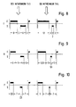
- Fig. 8 bis Fig. 10 je ein Ablaufdiagramm für drei verschiedene Trommel-Drehrhythmen im Intensiv-, Normal-und Feingang.
- 11 shows a schematic, broken-open representation of the tub and the drum of a drum washing machine,
- 2 to 4 each show a top view and a sectional view for three different embodiments of drivers of the laundry drum,
- 5 and FIG. 6 show two operating phases of a laundry drum with a preferred type of laundry driver,
- Fig. 7 is a graph of the alkali level in the tub over a period of time during a rinse phase and
- 8 to 10 each show a flow chart for three different drum rotation rhythms in the intensive, normal and fine input.
Der Laugenbehälter 1 in Fig. 1 enthält in seinem oberen Bereich eine Einfüllöffnung 2 für aus einer Waschmittel-Einspülvorrichtung 3 zusammen mit Zulaufwasser eingeführtes Waschmittel.The tub 1 in FIG. 1 contains in its upper area a filling
Der Boden des in möglichst geringem Abstand zur Trommel 4 gehaltenen Laugenbehälters 1 hat eine Vertiefung 5, in der die zum Erwärmen der Lauge nötigen Heizkörper 6 angeordnet sind. An der tiefsten Stelle der Vertiefung 5 ist eine Auslauföffnung 7 angebracht, die durch einen Verschlußkörper 8 verschlossen gehalten wird, solange eine nicht dargestellte Laugenpumpe an der Abflußleitung 9 nicht saugt. Dieser Verschlußkörper 8 hat die Aufgabe, den Raum unterhalb der Abflußöffnung 7 solange verschlossen zu halten, wie sich zum Waschen der Wäsche benötigtes Waschmittel innerhalb des Laugenbehälters befindet.The bottom of the lye container 1, which is kept as close as possible to the drum 4, has a recess 5 in which the heating elements 6 required for heating the lye are arranged. At the deepest point of the recess 5 there is an outlet opening 7 which is kept closed by a
Im zunehmenden Bestreben, zum Waschen immer weniger Wasser und Waschmittel einzusetzen, hat sich in der jüngsten Zeit die zum Waschen erforderliche Wassermenge so sehr verringert, daß die Wäschetrommel 4 nur noch geringfügig in die am Boden des Laugenbehälters 1 befindliche Lauge eintaucht. Hierdurch entsteht jedoch eine neuartige, durch die Trommelwaschmaschine der DE-OS 37 12 118 teilweise bereits behobene Schwierigkeit: Die am Boden der Wäschetrommel 1 lagernde Wäsche 10 kommt bei Trommelwaschmaschinen ohne Schöpfeinrichtungen in nicht mehr ausreichendem Maße in Berührung mit der Lauge, so daß die Wäsche nur noch äußerst langsam und sehr unvollständig benetzt wird. Eine ausreichende Waschwirkung kann bei derartigen Trommelwaschmaschinen mit extrem niedrigen Wasserständen daher auch dann nicht erreicht werden, wenn während der Benetzungsphase die Trommeldrehzahl auf einen Wert (z.B. 30 min-1) unterhalb der Waschdrehzahl (z.B. 50 min-1) reduziert wird.In the increasing endeavor to use less and less water and detergent for washing, the amount of water required for washing has recently decreased so much that the washing drum 4 is only slightly immersed in the lye located at the bottom of the tub 1. However, this creates a new type of difficulty, which has already been partially rectified by the drum washing machine of DE-OS 37 12 118: The
Die aus der DE-OS 37 12 118 bekannte Trommelwaschmaschine hat daher am Umfang im Bereich der Mitnehmer 11 Schöpfvorrichtungen 12, die beim Drehen der Trommel, z.B. in Richtung des Pfeiles 13, aus dem in der Vertiefung 5 stehenden Laugenvorrat den jeweiligen Zwischenspeicherraum, hier den Mitnehmer 11, füllen können. Während der Aufwärtsbewegung des Mitnehmers wird diese geschöpfte Wassermenge zunächst zwischengespeichert und über Auslaßöffnungen in dem Zwischenspeicherraum erst in den Trommelinnenraum abgegeben, wenn der Zwischenspeicherraum eine gewisse Höhe im Bereich unter oder über der waagerechten Trommelachse 15, vorzugsweise aber über der in der Trommel 4 liegenden, vollständig benetzten Wäsche 10, erreicht hat. Durch die Pfeile 14 ist angedeutet, in welcher Weise das derartig hochgehobene Wasser über die Wäsche 10 regnet.The drum washing machine known from DE-OS 37 12 118 therefore has scooping
Die Mitnehmer 11 können gemäß Fig. 2 durch Schottwände 23 in mehrere gleich große Kammern 25 unterteilt sein. Hierin sind sie sich den Mitnehmern in Fig. 6 der DE-OS 37 12 118 ähnlich. Die entlang dem Mitnehmer verteilten Kammern 25 haben wiederum ähnlich dem bekannten Mitnehmer abwechselnd in die eine und in die andere Drehrichtung weisende Schöpflöffel 20 als Schöpfvorrichtungen für die Mitnehmer. Im Gegensatz zum bekannten Mitnehmer hat der dachförmige Teil des Mitnehmers jedoch lediglich auf der dem Schöpflöffel 20 gegenüberliegenden Dachfläche Flutlöcher 17, durch die emporgehobene Lauge abgeregnet werden kann. Die Flutlöcher sind in dieser jeweils einen Dachfläche aber nur in der Nähe der Dachspitze angeordnet, damit sich im Raumwinkel am Fuße dieser Dachfläche zum Emporheben genügend Lauge ansammeln kann. In der durch den Pfeil 13 angedeuteten Schöpfdrehrichtung schöpft der rechte Schöpflöffel 20 Lauge in die Kammer 25.The
Gleichzeitig dringt auch Lauge durch die bekanntermaßen im Trommelmantel zwischen den Mitnehmern angeordnete Lochung gegen die Außenseite der ungelochten Dachfläche (siehe gestrichelte Pfeile) und wird vom Mitnehmer soweit angehoben, bis sie über die Dachspitze von oben auf die Wäsche herabfließt. Dies geschieht bereits, bevor die Kammer 25 ihren Inhalt durch die Flutlöcher 17 abregnet. Daher wird die Wäsche bereits während einer 1/3-Trommeldrehung durch einen einzigen Mitnehmer an unterschiedlichen Teilen benetzt.At the same time, lye also penetrates through the perforations, which are known to be arranged in the drum jacket between the drivers, against the outside of the unperforated roof surface (see dashed arrows) and is raised by the driver until it flows down over the top of the roof onto the laundry. This happens before the
Bei einer Dauer des Benetzungsabschnitts von 3 min einer Einschaltdauer von 30 % und einer Trommeldrehzahl von 30 min-1 wird die Wäsche 81 mal auf diese Weise benetzt. Hieraus erkennt man bereits die hohe Effektivität der Laugenzuführung zur Wäsche.With a duration of the wetting section of 3 min, a duty cycle of 30% and a drum speed of 30 min- 1 , the laundry is wetted 81 times in this way. From this you can already see the high effectiveness of the lye supply to the laundry.
Der Mitnehmer gemäß Fig. 4 enthält nur zwei Kammern 31 und 32, die ungleich groß sind. Hierdurch ergibt sich eine Vorzugsschöpfrichtung, deren Vorteile weiter unten beschrieben werden.4 contains only two
Fig. 4 zeigt einen Mitnehmer mit nur einer einzigen Kammer 41, deren Schöpflöffel nur in eine Richtung gerichtet sind. Entsprechend kann diese Kammer nur in einer Drehrichtung schöpfen.Fig. 4 shows a driver with only a
Die der jeweiligen Drehrichtung abgewandten Schöpflöffel 20 und zugeordneten Kammern aller Ausführungsbeispiele von Mitnehmern pumpen Lauge wieder aus der Wäschetrommel ab und fördern sie in den Zwischenraum zwischen Trommel und Laugenbehälter. Dadurch wird der Austausch zwischen der in der Wäsche befindlichen Lauge und der freien Lauge gefördert. Hieraus resultiert eine bessere Waschwirkung, weil von der Wäsche abgelöster Schmutz schneller aus der Wäsche herausgespült werden kann.The
Die in Fig. 5 dargestellte Wäschetrommel dreht sich gemäß Pfeil 13 in Schöpfdrehrichtung. Dabei schöpfen einerseits die Schöpflöffel 20 Lauge aus dem Laugenbehälter in den Mitnehmer 11 und andererseits die Flutlöcher 16 ebenfalls aus dem Zwischenraum zwischen der Trommel 4 und dem Laugenbehälter Lauge auf die ungelochten Dachflächen 26 der Mitnehmer 11. An dem weiter oben befindlichen Mitnehmer ist zu erkennen, daß gemäß dem Pfeil 18 geschöpfte Lauge von der Außenseite der Dachfläche 26 auf die unten liegende (in Fig. 5 und 6 nicht dargestellt) Wäsche fließt und kurze Zeit darauf ebenfalls geschöpfte Lauge durch die Flutlöcher 17 gemäß der Pfeile 14 aus dem Mitnehmer 11 auf die Wäsche regnet. Hieraus ist daher erkennbar, daß der Benetzungseffekt größer ist als beim Gegenstand der DE-OS 37 12 118.The laundry drum shown in FIG. 5 rotates in the direction of scooping according to
Die in Fig. 6 dargestellte Wäschetrommel dreht sich gemäß Pfeil 19 in Entleerungsdrehrichtung. Hierbei saugt der nach hinten offene, durch die Lauge am Boden des Laugenbehälters streichende Schöpflöffel 20 aus dem Innenraum des Mitnehmers 11 Lauge an, die durch die Flutlöcher 17 aus dem Innenraum der Trommel nachströmen muß. Diese Lauge stammt im wesentlichen gemäß Pfeil 21 aus der feuchten Wäsche und wird bei Trommeldrehzahlen bis zu etwa 60 min-1 auch durch die Flutlöcher 16 im Trommelmantel aus dem Zwischenraum zwischen Trommel und Laugenbehälter gesaugt. Bei darüber liegenden Drehzahlen überwiegt jedoch die Zentrifugalkraft, so daß Feuchtigkeit nur aus dem Trommelinneren angesaugt wird.The laundry drum shown in FIG. 6 rotates according to
Während des Benetzungsabschnitts wird gemäß dem erfindungsgemäßen Verfahren die Wäschetrommel mit höchstens 30 % Einschaltdauer intervallartig angetrieben. Wäschetrommeln, deren Mitnehmer gemäß Fig. 2 und 3 gestaltet sind, können reversierend angetrieben werden.During the wetting section, according to the method according to the invention, the laundry drum is driven at intervals with a maximum of 30% duty cycle. Laundry drums, the drivers of which are designed according to FIGS. 2 and 3, can be driven reversing.
Bei Mitnehmern gemäß Fig. 2, bei denen die Volumina der jeder Drehrichtung zugeordneten Kammern gleich groß sind, kann der Reversierrhythmus ebenfalls gleichmäßig verteilt sein, z.B. 3 s Linkslauf, 9 s Pause, 3 s Rechtslauf und 9 s Pause. Dabei ergeben sich insgesamt 24 s für ein Intervall und 25 % Einschaltdauer.In the case of drivers according to FIG. 2, in which the volumes of the chambers assigned to each direction of rotation are of the same size, the reversing rhythm can also be distributed uniformly, e.g. 3 s anticlockwise rotation, 9 s pause, 3 s clockwise rotation and 9 s pause. This results in a total of 24 s for an interval and 25% duty cycle.
Bei Mitnehmern gemäß Fig. 3, bei denen die Volumina der jeder Drehrichtung zugeordneten Kammern 31 und 32 ungleich groß sind, hier z.B. 3x V31 = V32, kann der Reversierrhythmus umgekehrt proportional verteilt sein, damit bei jedem Schöpfvorgang der Wäsche die gleiche Beregnungsmenge zugeführt wird, z.B. 3 s Linkslauf, 14 s Pause, 9 s Rechtslauf, 14 s Pause. Dabei ergeben sich insgesamt 40 s für ein Intervall und 30 % Einschaltdauer.3, in which the volumes of the
Wäschetrommeln, deren Mitnehmer nur eine Kammer 41 mit in einer Drehrichtung wirkendem Schöpflöffel 20 gemäß Fig. 4 aufweisen, werden im Benetzungsabschnitt zweckmäßigerweise auch nur in dieser einen Drehrichtung betrieben. Beispielsweise kann die Wäschetrommel in jedem Intervall 5 s lang laufen und 15 s lang stehen, das ist eine Einschaltdauer von 25 %.Laundry drums, the drivers of which only have a
Während der Stillstandzeiten der Wäschetrommel sickert die abgeregnete Lauge langsam in Schwerkraftrichtung durch die Wäsche, ehe die Wäsche in der anschließenden Laufphase wieder umgeschichtet wird.During the downtimes of the laundry drum, the rainy liquor slowly seeps through the laundry in the direction of gravity before the laundry is shifted again in the subsequent running phase.
Während des Klarwäscheabschnitts wird die Wäschetrommel anders als im Benetzungsabschnitt angetrieben. Da es hier nicht mehr auf eine optimale Benetzung sondern auf eine optimale mechanische Behandlung der Wäsche ankommt, wird die Wäschetrommel während des Klarwäscheabschnitts - außer zur Behandlung von empfindlicher Wäsche wie Wolle - mit einer üblichen Trommeldrehzahl angetrieben, z.B. 55 min-1. During the rinse section, the laundry drum is driven differently than in the wetting section. Since it is no longer a question of optimal wetting, but of an optimal mechanical treatment of the laundry, the laundry drum is driven at a normal drum speed during the rinse cycle section - except for the treatment of delicate laundry such as wool, for example 55 min- 1.
Außerdem kann der Klarwäscheabschnitt gemäß Fig. 7 in Wasch-Schleuderphasen WSP und Reversierphasen RP unterteilt sein. In den Wasch-Schleuderphasen wird die Wäschetrommel in Entleerungsrichtung aus dem Stillstand beschleunigt, bis beispielsweise eine Drehzahl von 300 min-1 erreicht ist. Dieser Vorgang dauert etwa 10 s. Der Schleuderanlauf kann auch zeitlich begrenzt sein; dann wird die erreichte Enddrehzahl durch die Beladung der Wäschetrommel bestimmt. Sie wird möglicherweise zwischen 150 min-1 und 350 min-1 variieren.7 can be subdivided into wash-spin phases WSP and reverse phases RP. In the wash-spin-extraction phases, the washing drum is accelerated in the discharge direction from a standstill, until it reaches, for example, a speed of 300 min-. 1 This process takes about 10 seconds. The spin start can also be limited in time; then the final speed reached is determined by the loading of the laundry drum. It may vary between 150 min- 1 and 350 min- 1 .
An eine Wasch-Schleuderphase WSP schließt sich im Klarwäscheabschnitt eine Reversierphase RP an, während der die Trommel im Reversierbetrieb angetrieben wird. Hierzu kann je nach den mechanischen Behandlungsanforderungen und je nach der Wäscheempfindlichkeit ein Normal-, Intensiv- oder Feingang angewendet werden. Diese Reversierphase dauert beispielsweise 80 s.A wash-spin phase WSP is followed by a reversing phase RP in the clear wash section, during which the drum is driven in reversing mode. Depending on the mechanical treatment requirements and the laundry sensitivity, a normal, intensive or fine input can be used for this. This reversing phase lasts for example 80 s.
Die Aufteilung des Klarwäscheabschnitts in Wasch-Schleuderphasen WSP und Reversierphasen RP hat folgenden vorteilhaften Effekt:
- Während der Reversierphasen wird bekanntermaßen soviel Lauge, wie
von den Schöpflöffeln 20 erfaßt werden kann, in den Trommelinnenraum, nämlich indie Wäsche 10 transportiert. Da aus der Wäsche immer wieder etwas überschüssige Lauge zurücktropft, stellt sich ein Gleichgewicht zwischen geschöpfter und zurückfließender Lauge ein. Aufgrund dieses ständigen Laugenflusses durch die Wäsche wird abgelöster Schmutz effektiver aus der Wäsche transportiert. Entsprechend wird ein bestimmtes Niveau RNiv erreicht bzw. eingehalten.
- As is known, as much lye as can be picked up by the
scoops 20 is transported into the drum interior, namely into thelaundry 10, during the reversing phases. Since a little surplus lye drips back and forth from the wash, there is a balance between the lye and the lye flowing back. Due to this constant flow of lye through the laundry, detached dirt is transported out of the laundry more effectively. Accordingly, a certain level RNiv is reached or maintained.
Während der Wasch-Schleuderphasen wird zusätzlich schmutzige Lauge weitgehend abgeschleudert und durch den zu Fig. 6 beschriebenen Effekt aus der Wäschetrommel in den Zwischenraum zum Laugenbehälter befördert. Hierdurch wird das Schmutz-Ablöseverhalten noch weiter verbessert und außerdem das Niveau im Laugenbehälter kurzzeitig bis auf den Pegel WSNiv erhöht.During the washing and spinning phases, dirty lye is also largely thrown off and transported from the washing drum into the intermediate space to the tub by the effect described for FIG. 6. This further improves the dirt removal behavior and also temporarily increases the level in the tub to the WSNiv level.
Es hat sich außerdem als vorteilhaft erwiesen, während der Reversierphase die Verringerung des Laugenstandes im Laugenbehälter verzögert einzustellen. Bei Schöpf-Drehrichtung wären nämlich an sich nur wenige Schöpfvorgänge während beispielsweise zwei Trommelumdrehungen notwendig, um das Niveau RNiv wieder zu erreichen. Einen besseren Reinigungseffekt ergibt aber ein Reversierbetrieb, in dem das Verhältnis von geschöpfter und entleerter Laugenmenge nur wenig zugunsten der geschöpften Menge ausgelegt ist. Der verbesserte Effekt beruht z.T. darauf, daß hierbei eine Schaumbildung weitgehend vermieden wird.It has also proven to be advantageous to delay the reduction of the suds level in the suds container during the reversing phase. With the scooping direction of rotation, only a few scooping operations would be necessary during, for example, two drum revolutions in order to reach the level RNiv again. A reversing operation, however, results in a better cleaning effect, in which the ratio of scooped and emptied lye amount is only slightly designed in favor of the scooped amount. The improved effect is partly due to ensure that foaming is largely avoided.
Bestimmend für dieses Verhältnis von geschöpfter und entleerter Laugenmenge ist einerseits das Verhältnis der Volumina der jeweiligen Kammern in den Mitnehmern und andererseits die Verteilung des Trommelbetriebs auf die jeweiligen Drehrichtungen.The ratio of the volume of the respective chambers in the drivers and, on the other hand, the distribution of the drum operation over the respective directions of rotation are decisive for this ratio of the amount of lye emptied and emptied.
Eine Mitnehmergestaltung gemäß Fig. 2 fällt für diese Anwendung aus; denn dieser Mitnehmer würde in beiden Drehrichtungen gleichviel Laugenmenge schöpfen. Daher betrachten wir nur die Mitnehmer gemäß Fig. 3 und 4.A driver design according to FIG. 2 fails for this application; because this driver would draw the same amount of lye in both directions of rotation. Therefore, we only consider the drivers according to FIGS. 3 and 4.
Für drei unterschiedlich intensive Trommelbetriebsmöglichkeiten "Intensivgang" I, "Normalgang" N und "Feingang" F, bei denen die Trommel-Betriebsdauer im Verhältnis zur Stillstandsdauer von 70 % Einschaltdauer beim Intensivgang, 50 % Einschaltdauer beim Normalgang und 30 % Einschaltdauer beim Feingang variiert werden kann, sind in den Figuren 8 bis 10 drei Diagramme gezeichnet. Im jeweils linken Intervall sind die Trommel-Betriebsweisen für Mitnehmer gemäß Fig. 3 und im jeweils rechten Intervall diejenigen für Mitnehmer gemäß Fig. 4 dargestellt.For three differently intensive drum operating options "Intensive gear" I, "Normal gear" N and "Feingang" F, in which the drum operating time is varied in relation to the downtime of 70% duty cycle in intensive gear, 50% duty cycle in normal gear and 30% duty cycle in fine input can, three diagrams are drawn in Figures 8 to 10. The drum operating modes for drivers are in the
E bedeutet den Trommelbetrieb in Entleerungsdrehrichtung und S den Trommelbetrieb in Schöpftdrehrichtung (in Fig. 3 jeweils auf die größere Kammer 32 bezogen).E means the drum operation in the emptying direction of rotation and S the drum operation in the scooping direction of rotation (in FIG. 3 in each case related to the larger chamber 32).
In Fig. 8 ist der Intensivgang für Mitnehmer nach Fig. 3 in 8 s Entleerungsdrehrichtung, 3 s Stillstand, 6 s Schöpfdrehrichtung und wieder 3 s Stillstand aufgeteilt, für Mitnehmer nach Fig. 4 in 12 s Entleerungsdrehrichtung, 3 s Stillstand, 2 s Schöpfdrehrichtung und 3 s Stillstand.In FIG. 8, the intensive aisle for drivers according to FIG. 3 is divided into 8 s emptying rotation direction, 3 s standstill, 6 s scooping rotation direction and again 3 s stoppage, for drivers according to FIG. 4 in 12 s emptying rotation direction, 3 s standing still, 2 s scooping rotation direction and 3 s standstill.
Entprechend weisen der Normalgang gemäß Fig. 9 für Mitnehmer nach Fig. 3 6 s Entleerungsdrehrichtung, 5 s Stillstand, 4 s Schöpfdrehrichtung und 5 s Stillstand bzw. für Mitnehmer gemäß Fig. 4 8,5 s Entleerungsdrehrichtung, 5 s Stillstand, 1,5 s Schöpfdrehrichtung und 5 s Stillstand sowie der Feingang gemäß Fig. 10 für Mitnehmer nach Fig. 3 3,5 s Entleerungsdrehrichtung, 7 s Stillstand, 2,5 s Schöpfdrehrichtung und 7 s Stillstand bzw. für Mitnehmer gemäß Fig. 4 5 s Entleerungsdrehrichtung, 7 s Stillstand, 1 s Schöpfdrehrichtung und 7 s Stillstand auf. Die symmetrische Aufteilung der Stillstandszeiten nach jedem Lauf kann ebenfalls noch aufgegeben werden. Beispielsweise kann es von Vorteil sein, wenn die Stillstandszeiten nach jedem Lauf in Schöpfdrehrichtung länger sind als nach der Entleerungsdrehrichtung, damit die Lauge länger Gelegenheit hat, durch die Wäsche zu sikkern.Correspondingly, the normal gear according to FIG. 9 for drivers according to FIG. 3 shows 6 s emptying direction of rotation, 5 s standstill, 4 s scooping direction of rotation and 5 s standstill or for drivers according to FIG. 4 8.5 s emptying direction of rotation, 5 s standstill, 1.5 s scoop direction of rotation and 5 s standstill and the inlet according to FIG. 10 for drivers according to FIG. 3 3.5 s emptying direction of rotation, 7 s standstill, 2.5 s scoop direction of rotation and 7 s standstill or for drivers according to FIG. 4 5 s emptying direction of rotation, 7 s standstill, 1 s scoop direction of rotation and 7 s standstill. The symmetrical distribution of downtimes after each run can also be abandoned. For example, it may be advantageous if the downtimes after each run in the scoop direction of rotation are longer than after the emptying direction of rotation, so that the lye has a longer opportunity to dribble through the laundry.
Der Spülabschnitt wird ebenfalls mit einem reversierten Trommelbetrieb abgehalten, der so eingestellt ist, daß ähnlich der Fig. 7 das Niveau im Laugenbehälter antizyklisch zur in der Wäsche befindlichen Laugenmenge steigt und fällt. Beispielsweise kann der Anteil des Trommelantriebs in Schöpfdrehrichtung größer sein als in Entleerungsdrehrichtung. Je nach Verwendung der vorgeschlagenen Mitnehmer wird man die Anteile der jeweiligen Trommel-Drehrichtungen bemessen. Hierdurch werden die Spülwasserströmung durch die Wäsche intensiviert und die Laugenreste besser ausgespült. Im übrigen können die Erkenntnisse aus dem zuvor beschriebenen Klarwäscheabschnitt berücksichtigt werden.The rinsing section is also held with a reversed drum operation, which is set so that, similar to FIG. 7, the level in the tub rises and falls counter-cyclically to the amount of tubing in the laundry. For example, the proportion of the drum drive in the scoop rotation direction can be larger than in the discharge rotation direction. Depending on the use of the proposed drivers, the proportions of the respective drum directions of rotation will be measured. As a result, the rinse water flow through the laundry is intensified and the lye residues are better rinsed out. Otherwise, the findings from the clear wash section described above can be taken into account.
Der Schleuderabschnitt einer solchen Trommelwaschmaschine verläuft in bekannter Weise, wobei die Trommel nur in Entleerungs-Drehrichtung antreibbar sein soll. In der anderen Drehrichtung würden abgeschleuderte Laugenreste wieder vom Schöpflöffel 20 aufgefangen und in den Innenraum der Trommel befördert werden.The centrifugal section of such a drum washing machine runs in a known manner, the drum should only be drivable in the emptying direction of rotation. In the other direction of rotation, detached lye residues would be caught again by the
Claims (10)
Applications Claiming Priority (3)
| Application Number | Priority Date | Filing Date | Title |
|---|---|---|---|
| DE3741177 | 1987-12-04 | ||
| DE19873741177 DE3741177A1 (en) | 1987-12-04 | 1987-12-04 | METHOD FOR OPERATING A DRUM WASHING MACHINE AND DRUM WASHING MACHINE FOR CARRYING OUT THE METHOD |
| EP88119095A EP0318761B1 (en) | 1987-12-04 | 1988-11-17 | Method for using a drum washing machine and machine to perform this method |
Related Parent Applications (1)
| Application Number | Title | Priority Date | Filing Date |
|---|---|---|---|
| EP88119095.3 Division | 1988-11-17 |
Publications (2)
| Publication Number | Publication Date |
|---|---|
| EP0475462A1 true EP0475462A1 (en) | 1992-03-18 |
| EP0475462B1 EP0475462B1 (en) | 1995-05-10 |
Family
ID=6341907
Family Applications (2)
| Application Number | Title | Priority Date | Filing Date |
|---|---|---|---|
| EP91118837A Expired - Lifetime EP0475462B1 (en) | 1987-12-04 | 1988-11-17 | Method for using a drum washing machine and washing machine to perform this method |
| EP88119095A Expired - Lifetime EP0318761B1 (en) | 1987-12-04 | 1988-11-17 | Method for using a drum washing machine and machine to perform this method |
Family Applications After (1)
| Application Number | Title | Priority Date | Filing Date |
|---|---|---|---|
| EP88119095A Expired - Lifetime EP0318761B1 (en) | 1987-12-04 | 1988-11-17 | Method for using a drum washing machine and machine to perform this method |
Country Status (3)
| Country | Link |
|---|---|
| EP (2) | EP0475462B1 (en) |
| DE (3) | DE3741177A1 (en) |
| ES (2) | ES2073094T3 (en) |
Cited By (6)
| Publication number | Priority date | Publication date | Assignee | Title |
|---|---|---|---|---|
| US5560061A (en) * | 1993-03-31 | 1996-10-01 | Bosch-Siemens Hausgeraete Gmbh | Washing machine with a reversing-mode washing drum |
| DE102005003696A1 (en) * | 2005-01-26 | 2006-07-27 | BSH Bosch und Siemens Hausgeräte GmbH | A method for reducing the risk shrinking delicate washing materials in horizontal axis clothes washing machines has short drum rotations all in the same direction to drain trapped liquor on the clothes |
| WO2006108722A1 (en) * | 2005-04-11 | 2006-10-19 | BSH Bosch und Siemens Hausgeräte GmbH | Method for washing shrinkable textiles and a washing machine for carrying out said method |
| WO2008003594A1 (en) * | 2006-07-06 | 2008-01-10 | BSH Bosch und Siemens Hausgeräte GmbH | Washing machine with hollow drivers |
| KR100802256B1 (en) | 2001-07-26 | 2008-02-11 | 베에스하 보쉬 운트 지멘스 하우스게랫테 게엠베하 | Method for operating a programmable washing machine and a washing machine suited therefor |
| CN104088116A (en) * | 2014-06-24 | 2014-10-08 | 上海百强洗涤设备制造有限公司 | Novel inner-roller structure of tunnel type washing auger |
Families Citing this family (7)
| Publication number | Priority date | Publication date | Assignee | Title |
|---|---|---|---|---|
| DE4205691A1 (en) * | 1992-02-25 | 1993-08-26 | Waschgeraete Gmbh | DRUM FOR A WASHING MACHINE |
| KR100195453B1 (en) * | 1996-05-11 | 1999-06-15 | 윤종용 | Lifter of drum type washing machine |
| DE10054947A1 (en) * | 2000-11-06 | 2002-05-08 | Bsh Bosch Siemens Hausgeraete | Treatment of laundry in washing machine with rotationally located washing drum in which laundry is received and liquid during washing method flows through washing drum in laundry or washing and out from it and drum in operation of machine |
| DE10234473A1 (en) | 2002-07-29 | 2004-02-12 | BSH Bosch und Siemens Hausgeräte GmbH | A method for acceleration of the absorption of water in the dry wash load of an automatic washing machine, using a controlled sequence of alternate direction tumbles at different speeds |
| DE10326551A1 (en) | 2003-06-12 | 2005-01-05 | BSH Bosch und Siemens Hausgeräte GmbH | Washing and rinsing process for a washing machine |
| DE102006031354A1 (en) * | 2006-07-06 | 2008-01-17 | BSH Bosch und Siemens Hausgeräte GmbH | Method for operating a washing machine and washing machine suitable for this purpose |
| DE102009002782B4 (en) * | 2009-05-04 | 2012-02-23 | BSH Bosch und Siemens Hausgeräte GmbH | A method of rinsing in a washing machine with a rinse step at high drum speed |
Citations (4)
| Publication number | Priority date | Publication date | Assignee | Title |
|---|---|---|---|---|
| FR1299679A (en) * | 1961-06-15 | 1962-07-27 | Device for circulating baths in washing, bleaching, rinsing and other similar devices | |
| DE1610132A1 (en) * | 1967-04-07 | 1971-04-08 | Siemens Elektrogeraete Gmbh | Method for operating an automatically controlled drum washing machine |
| FR2548699A1 (en) * | 1983-07-07 | 1985-01-11 | Miele & Cie | WASHING METHOD FOR PROGRAM CONTROL DRUM WASHING MACHINE |
| EP0245721A1 (en) * | 1986-05-06 | 1987-11-19 | Bosch-Siemens HausgerÀ¤te GmbH | Washing machine drum provided with means for wetting the laundry |
-
1987
- 1987-12-04 DE DE19873741177 patent/DE3741177A1/en not_active Withdrawn
-
1988
- 1988-11-17 DE DE3853786T patent/DE3853786D1/en not_active Expired - Lifetime
- 1988-11-17 ES ES91118837T patent/ES2073094T3/en not_active Expired - Lifetime
- 1988-11-17 ES ES198888119095T patent/ES2032934T3/en not_active Expired - Lifetime
- 1988-11-17 DE DE8888119095T patent/DE3872676D1/en not_active Expired - Lifetime
- 1988-11-17 EP EP91118837A patent/EP0475462B1/en not_active Expired - Lifetime
- 1988-11-17 EP EP88119095A patent/EP0318761B1/en not_active Expired - Lifetime
Patent Citations (4)
| Publication number | Priority date | Publication date | Assignee | Title |
|---|---|---|---|---|
| FR1299679A (en) * | 1961-06-15 | 1962-07-27 | Device for circulating baths in washing, bleaching, rinsing and other similar devices | |
| DE1610132A1 (en) * | 1967-04-07 | 1971-04-08 | Siemens Elektrogeraete Gmbh | Method for operating an automatically controlled drum washing machine |
| FR2548699A1 (en) * | 1983-07-07 | 1985-01-11 | Miele & Cie | WASHING METHOD FOR PROGRAM CONTROL DRUM WASHING MACHINE |
| EP0245721A1 (en) * | 1986-05-06 | 1987-11-19 | Bosch-Siemens HausgerÀ¤te GmbH | Washing machine drum provided with means for wetting the laundry |
Cited By (9)
| Publication number | Priority date | Publication date | Assignee | Title |
|---|---|---|---|---|
| US5560061A (en) * | 1993-03-31 | 1996-10-01 | Bosch-Siemens Hausgeraete Gmbh | Washing machine with a reversing-mode washing drum |
| KR100802256B1 (en) | 2001-07-26 | 2008-02-11 | 베에스하 보쉬 운트 지멘스 하우스게랫테 게엠베하 | Method for operating a programmable washing machine and a washing machine suited therefor |
| DE102005003696A1 (en) * | 2005-01-26 | 2006-07-27 | BSH Bosch und Siemens Hausgeräte GmbH | A method for reducing the risk shrinking delicate washing materials in horizontal axis clothes washing machines has short drum rotations all in the same direction to drain trapped liquor on the clothes |
| WO2006079428A1 (en) | 2005-01-26 | 2006-08-03 | BSH Bosch und Siemens Hausgeräte GmbH | Program controlled washing machine |
| CN101103152B (en) * | 2005-01-26 | 2012-05-09 | Bsh博世和西门子家用器具有限公司 | Program-controlled washing machine |
| WO2006108722A1 (en) * | 2005-04-11 | 2006-10-19 | BSH Bosch und Siemens Hausgeräte GmbH | Method for washing shrinkable textiles and a washing machine for carrying out said method |
| EA011757B1 (en) * | 2005-04-11 | 2009-06-30 | Бсх Бош Унд Сименс Хаусгерете Гмбх | Method for washing shrinkable textiles and a washing machine for carrying out said method |
| WO2008003594A1 (en) * | 2006-07-06 | 2008-01-10 | BSH Bosch und Siemens Hausgeräte GmbH | Washing machine with hollow drivers |
| CN104088116A (en) * | 2014-06-24 | 2014-10-08 | 上海百强洗涤设备制造有限公司 | Novel inner-roller structure of tunnel type washing auger |
Also Published As
| Publication number | Publication date |
|---|---|
| DE3741177A1 (en) | 1989-06-15 |
| EP0318761A1 (en) | 1989-06-07 |
| EP0475462B1 (en) | 1995-05-10 |
| ES2032934T3 (en) | 1993-03-01 |
| EP0318761B1 (en) | 1992-07-08 |
| DE3872676D1 (en) | 1992-08-13 |
| ES2073094T3 (en) | 1995-08-01 |
| DE3853786D1 (en) | 1995-06-14 |
Similar Documents
| Publication | Publication Date | Title |
|---|---|---|
| EP2044253B1 (en) | Washing machine with hollow drivers | |
| EP0245721B1 (en) | Washing machine drum provided with means for wetting the laundry | |
| EP0475462B1 (en) | Method for using a drum washing machine and washing machine to perform this method | |
| DE736334C (en) | Washing machine for washing and spin drying of items of laundry | |
| EP0043122B1 (en) | Method of washing laundry, and washing machine with drum for performing the method | |
| EP2049723B1 (en) | Determination of the water storage capacity of textiles in a washing machine, and corresponding washing machine | |
| EP1190135A1 (en) | Front-loading washing machine comprising a rotatable laundry basket | |
| EP1846607B1 (en) | Method for cleaning and waterproofing textiles | |
| DE4104450A1 (en) | Washing textiles in automatic washing machine - by using twin drum principle and recycling container to store solns. | |
| DE4326496C2 (en) | Drum washing machine with a rotatable washing drum | |
| DD150633A5 (en) | METHOD AND DEVICE FOR WASHING WAESCHE | |
| DE2226992C3 (en) | Countercurrent washing process in a washing machine consisting of several washing units | |
| EP1417369B1 (en) | Method for operating a programmable washing machine and a washing machine suited therefor | |
| DE69907902T2 (en) | WASHING MACHINE | |
| DE3820409C2 (en) | ||
| DE4331632C2 (en) | Process for washing and spinning laundry in a program-controlled washing machine | |
| DE3506948C2 (en) | Process for removing lint from a textile washing machine and textile washing machine | |
| EP0304391A1 (en) | Drum washing machine | |
| DE102015101456A1 (en) | Drum for a washing machine and washing machine | |
| DE831537C (en) | Washing machine facility | |
| DE3818157A1 (en) | WASHING MACHINE | |
| DE19824403A1 (en) | Process for filling water in a program-controlled washing machine | |
| DE102004012761B4 (en) | Washing machine with collecting container | |
| DE4205691A1 (en) | DRUM FOR A WASHING MACHINE | |
| DE3902386C2 (en) | Device for washing textiles |
Legal Events
| Date | Code | Title | Description |
|---|---|---|---|
| PUAI | Public reference made under article 153(3) epc to a published international application that has entered the european phase |
Free format text: ORIGINAL CODE: 0009012 |
|
| AC | Divisional application: reference to earlier application |
Ref document number: 318761 Country of ref document: EP |
|
| AK | Designated contracting states |
Kind code of ref document: A1 Designated state(s): DE ES FR IT |
|
| 17P | Request for examination filed |
Effective date: 19920825 |
|
| RAP3 | Party data changed (applicant data changed or rights of an application transferred) |
Owner name: BOSCH-SIEMENS HAUSGERAETE GMBH |
|
| 17Q | First examination report despatched |
Effective date: 19940328 |
|
| GRAA | (expected) grant |
Free format text: ORIGINAL CODE: 0009210 |
|
| AC | Divisional application: reference to earlier application |
Ref document number: 318761 Country of ref document: EP |
|
| AK | Designated contracting states |
Kind code of ref document: B1 Designated state(s): DE ES FR IT |
|
| REF | Corresponds to: |
Ref document number: 3853786 Country of ref document: DE Date of ref document: 19950614 |
|
| ITF | It: translation for a ep patent filed |
Owner name: STUDIO JAUMANN |
|
| ET | Fr: translation filed | ||
| REG | Reference to a national code |
Ref country code: ES Ref legal event code: FG2A Ref document number: 2073094 Country of ref document: ES Kind code of ref document: T3 |
|
| PLBE | No opposition filed within time limit |
Free format text: ORIGINAL CODE: 0009261 |
|
| STAA | Information on the status of an ep patent application or granted ep patent |
Free format text: STATUS: NO OPPOSITION FILED WITHIN TIME LIMIT |
|
| 26N | No opposition filed | ||
| PGFP | Annual fee paid to national office [announced via postgrant information from national office to epo] |
Ref country code: ES Payment date: 20021127 Year of fee payment: 15 |
|
| PG25 | Lapsed in a contracting state [announced via postgrant information from national office to epo] |
Ref country code: ES Free format text: LAPSE BECAUSE OF NON-PAYMENT OF DUE FEES Effective date: 20031118 |
|
| REG | Reference to a national code |
Ref country code: ES Ref legal event code: FD2A Effective date: 20031118 |
|
| PGFP | Annual fee paid to national office [announced via postgrant information from national office to epo] |
Ref country code: DE Payment date: 20071130 Year of fee payment: 20 |
|
| PGFP | Annual fee paid to national office [announced via postgrant information from national office to epo] |
Ref country code: IT Payment date: 20071127 Year of fee payment: 20 |
|
| PGFP | Annual fee paid to national office [announced via postgrant information from national office to epo] |
Ref country code: FR Payment date: 20071120 Year of fee payment: 20 |