EP0475112B1 - Appareil pour la formation du col d'une petite bouteille en verre - Google Patents
Appareil pour la formation du col d'une petite bouteille en verre Download PDFInfo
- Publication number
- EP0475112B1 EP0475112B1 EP91113745A EP91113745A EP0475112B1 EP 0475112 B1 EP0475112 B1 EP 0475112B1 EP 91113745 A EP91113745 A EP 91113745A EP 91113745 A EP91113745 A EP 91113745A EP 0475112 B1 EP0475112 B1 EP 0475112B1
- Authority
- EP
- European Patent Office
- Prior art keywords
- finger
- shaping
- glass tube
- circular
- glass
- Prior art date
- Legal status (The legal status is an assumption and is not a legal conclusion. Google has not performed a legal analysis and makes no representation as to the accuracy of the status listed.)
- Expired - Lifetime
Links
Images

Classifications
-
- C—CHEMISTRY; METALLURGY
- C03—GLASS; MINERAL OR SLAG WOOL
- C03B—MANUFACTURE, SHAPING, OR SUPPLEMENTARY PROCESSES
- C03B23/00—Re-forming shaped glass
- C03B23/04—Re-forming tubes or rods
- C03B23/11—Reshaping by drawing without blowing, in combination with separating, e.g. for making ampoules
- C03B23/112—Apparatus for conveying the tubes or rods in a curved path around a vertical axis through one or more forming stations
-
- C—CHEMISTRY; METALLURGY
- C03—GLASS; MINERAL OR SLAG WOOL
- C03B—MANUFACTURE, SHAPING, OR SUPPLEMENTARY PROCESSES
- C03B23/00—Re-forming shaped glass
- C03B23/04—Re-forming tubes or rods
- C03B23/09—Reshaping the ends, e.g. as grooves, threads or mouths
- C03B23/095—Reshaping the ends, e.g. as grooves, threads or mouths by rolling
Definitions
- the invention relates to a device for forming a vial, the mouth region being formed into an open, heat-softened end of a glass tube. Vials, such as ampoules, snap-cap jars, rolled rim vials, etc. are then produced from the shaped glass tube end.
- These small vials or ampoules are made from glass tubes in vial machines, in which a large number of glass tubes are kept rotated about their own longitudinal axis and gradually fed to individual forming stations. At such a molding station, the mouth area is also formed by rolling in the glass tube end using one or more molding rollers.
- Vial machines and molding stations of this type are known from DE-PS 15 96 410, 17 96 100 and 36 13 212.
- a molding finger is always assigned to a molding station, which is inserted into a glass tube moved up by the surface machine and is held in the glass tube from the inside to the end of the shaping process by means of molding rollers arranged at the molding station to support the heat-softened glass .
- the shaping can take place at a single shaping station, the vial machine then stopping at this and only moving on to one station after the shaping has been carried out.
- a machine for the production of glass objects in which a glass tube is constricted at a certain distance from its end at a heat-softened point.
- Form fingers are inserted into the open end of the glass tube and their ends serve as internal support for the form rollers, which process the heat-softened area of the glass tube to be deformed from the outside.
- Each chuck arranged on the periphery of a turntable for a glass tube is assigned a shaped finger which can be inserted in a straight line from below into the downwardly open end of the glass tube, the shaped fingers being movable outside the turntable.
- the shape finger Since the mouth of the shape finger is in contact with the heat-softened glass over a long period of time, the shape finger must be made from a high-quality, heat-resistant material.However, due to the conditions of use, it is necessary to change the shape finger frequently, in which case the vial production must be stopped each time. Even when using several shaping stations, as described in DE-PS 15 96 410, the wear of the shaping finger is still relatively great and there is also the difficulty that the tool holders rotating with the shaping fingers all relate to the longitudinal axis of the each glass tube brought up from the carousel must be adjusted so that a clean mouth shape is guaranteed. If the adjustment is no longer accurate enough, for example due to wear on the chain drive of the tool holder or on a tool holder itself, the entire Forming station with, for example, four tool holders can be overhauled as a whole unit.
- the invention has for its object to provide a device with which the molding process of a mouth molding can be carried out so that the wear on the molding finger is as low as possible.
- a slight misalignment of the shaping finger with respect to the longitudinal axis of the glass tube to be shaped should be possible.
- a form finger is assigned to each glass tube in a vial machine, so that after use of the form finger to form a mouth region, the form finger extends over the remaining angle of rotation of the carousel up to Can cool down at the beginning of the next molding cycle. Since a vial machine normally carries 12 to 24 glass tubes, the cooling time of the shaped finger in the method or the corresponding device according to the invention is at least 3 times as long as in the prior art, while still adjusting the shaped finger with respect to the axis of rotation of the glass tube to be molded is simplified and improved.
- an inexpensive, less high-temperature resistant material such as silver steel (material number according to German steel code 1.2210) can also be used instead of the previously customary one Tyrodur steel (material number 1.2842) can be used.
- the retracting and extending movement of the shaped finger can also take place in a two-dimensional movement line when the vial machine runs continuously, as is already proposed in CA-C-581 053.
- This arrangement of the form finger on the carousel of the vial machine also ensures that the form finger is always in phase with the associated glass tube, i.e. there is no need to coordinate the position with respect to the respective glass tube.
- the form finger is therefore always precisely in position and can be adjusted with simple means.
- the molding process of a mouth area normally takes place over several positions of the carousel of a vial machine, it being advantageous to heat the glass tube end again and again by means of a burner.
- the molding finger can be pulled out of the glass tube end for a short time without great effort and retracted after the heating, so that overheating of the molding finger is avoided.
- Such a short extension and retraction of the form finger is practically not possible in a continuous production according to the prior art because of the considerable mechanical effort involved and the adjustment problems that occur.
- a carousel which carries a plurality of glass tubes which can be rotated about their own longitudinal axis and at the same spacing from one another on a common circular path past a molding station which uses a shaping roller to guide the ends of the Glass tubes roll in successively, with a form finger supporting the heat-softened end of the glass tube from the inside during the rolling process.
- a shape finger is assigned to each glass tube, the shape fingers being arranged on the carousel.
- each form finger is arranged on two carriages, by means of which the form finger can be displaced in a two-dimensional line of motion essentially radially and in the longitudinal direction to the longitudinal axis of the associated glass tube.
- This enables the form finger to be guided in a particularly simple manner.
- the end position of the form finger can also be easily adjusted by adjusting the end positions of the individual carriages, one end position of the one carriage (horizontal carriage) bringing the form finger onto the longitudinal axis of the associated glass tube and the other carriage (vertical carriage) the form finger the end of the glass tube moves in, with the form finger at the correct height with respect to the form roller when the vertical slide is in its end position.
- the horizontal slide is necessary so that the form finger can be guided out of the area of the glass tube so that it can be released downwards for further processing in the vial machine.
- the form finger or the holder of the form finger is specially designed so that the wear and thus inaccuracies that occur when shaping the mouth can be further reduced.
- Such a shaping finger which is guided for the internal shaping of a mouth region into an open, heat-soft end of a glass tube that is rolled up by a shaping roller, preferably has a cross-sectional area that deviates from the usual circular cross-section and that only has one or more circular-section regions that are in Come into contact with the inner circumference of the mouth area and determine the inner radius of the mouth, but the cross-sectional area of the shaping finger as a whole is kept so large that the ratio of the cross-sectional area to the length of the (or) circular section area (s) is ⁇ 0.55 r ⁇ , where r is the radius of the circular section area.
- the shape finger which only has its Circular section area (s) comes into contact with the heat-softened glass tube end, has a relatively larger cross-sectional area for dissipating the amount of heat transferred to the form finger during this contact than a circle with the same radius or a corresponding pie-shaped circle segment.
- the shaped finger can dissipate the amount of heat transferred from its heat-softened glass tube end over its circular section area to its holder more quickly than a corresponding cylindrical shaped finger, as a result of which less heat occurs in this shaped finger under otherwise identical operating conditions.
- the cross-sectional area of the forming finger is not reduced to less than half the area of the full circle placed over the circular section area (s), that is to say if the cross-sectional area is ⁇ 0.5 r2 ⁇ ⁇ , so that there is still sufficient mass for heat dissipation at all.
- the circular section area should also not be too small, so that a sufficient smoothing of the inner circumference of the mouth area is ensured.
- a circular section range from 60 ° to 190 ° is advantageous, the circular section preferably being selected in a range from 100 ° to 150 °. If the shaped finger has, for example, two opposing circular section regions, these are preferably each in the range from 100 ° to 150 °.
- the shaped finger In order to support the lower glass edge of the heat-softened glass tube end, the shaped finger preferably has a support at its lower end, which has a circular peripheral surface and is arranged concentrically to the shaped finger, the radius of this support being larger than the radius of the circular section area.
- a step-shaped profiled roller is used in such Form fingers then set in such a way that the smaller form roller radius attaches to the circumferential surface of this support and, with the profile part with a larger radius, delimits an essentially rectangular cavity in cross-section area in which the heat-softened glass tube end is formed into a rolled edge or flanged edge of the bottle mouth.
- the radius of the circular section again determines the inner radius of the mouth, the larger radius of the form roller of the outer radius of the bottle neck and the smaller radius of the form roller determine the outer radius of the rolled rim.
- the radius of the circular section depends on the desired inner radius of the mouth.
- Form fingers with a radius between 2 mm and 20 mm can be used for special applications.
- the support on which the end of the glass tube is seated can have a surface sloping towards the center. This creates a conical mirror surface on the top of the bottle.
- the sloping surface can be at an angle of e.g. 5 ° or 7 °.
- the circumferential surface of the support can also have a recess in the area where the shaping roller is attached, so that the radius of the support is somewhat reduced in this area. This enables the outside diameter of the edge of the vial to be reduced, since the shaped disk can penetrate closer to the shaped finger here.
- Such a shape finger can be used in the mouth area of the vial to be molded also create undercuts.
- the upper part of the circular section region then has an extended projecting edge which can be designed as a step or as a slope and correspondingly represents a second circular section region with a larger radius than the first circular section region, both circular section regions being arranged concentrically.
- the rear area is then also milled free with respect to a solid cylinder, so that the shape finger can first be pushed back somewhat in the radial direction from the contact point of the circular section area / inner circumference of the mouth after the shaping has been completed, in order then to be pulled out without touching the mouth.
- Such a form finger is preferably used in conjunction with only one form roller, since the previously generally used use of two form rollers would have to use two correspondingly shaped form finger halves which can be displaced relative to one another and which, in order that they can be pushed together, have only a very small cross-sectional area with respect to a corresponding full circle can have, whereby a sufficient dissipation of heat is no longer guaranteed in every case.
- the above-described embodiments of the shaping finger according to the invention can be used with particular advantage when using only one shaping roller. If two form rollers are to be rolled in at 180 ° on the glass tube, the advantageous form finger is to be designed in a D 2h symmetry (symmetry of the cross section), two opposing circular section regions then being assigned to the form rollers. Especially when producing a mouth with a undercut area, however, the use of only one form roller and a form finger with C 2v symmetry is particularly favorable, since then no expensive means for pivoting against one another or shifting two form fingers in the mouth are necessary.
- the form finger can be sprayed with oil during operation, which can run practically over the entire form finger and is expediently collected in an oil collecting pan located directly below the form finger and is derived therefrom.
- the molding finger can also be designed with some horizontal play, or can be inserted into the heat-softened glass tube end with such play.
- the horizontal play allows a largely free movement of the form finger radially to the longitudinal axis of the glass tube. This is achieved, for example, by placing the form finger on an articulated bearing. This arrangement can optionally be combined with the measures described above.
- the form finger which is used to form the mouth area into the open, heat-softened end of the glass tube can be inserted and pulled out again after shaping and serves during the shaping to support the heat-softened end of the glass tube from the inside against the form roller rolling in from the outside of the glass tube end, is preferably connected via a retaining pin to a spherical bearing which limits its pivoting radius in one Bearing part is guided and thus determines the swivel radius of the form finger.
- This freedom of movement of the shaping finger in a range of at most ⁇ 1.0 mm, preferably up to ⁇ 0.5 mm) with respect to its normal axis has proven to be favorable.
- a vial can be formed, in which the mouth region is first formed into an open, heat-softened end of a glass tube by means of a shaping roller and the shaping finger, which is used to shape the thermally softened end of the glass tube and to support it against the shaping roller in front of the
- the molding process is inserted into the glass tube end and then withdrawn again.
- the glass tube end is then separated from the glass tube and formed into a finished vial by forming a vial bottom.
- the molding finger is introduced into the heat-softened glass tube end with horizontal or radial play and centered there by the rolled-up glass tube end.
- a locking element is provided, which e.g. can be a locking pin in the spherical bearing.
- the bearing part sits on one again Vertical slide, which in turn is arranged on a horizontal slide, so that the form finger can be moved on the one hand in the radial direction and on the other hand in the longitudinal direction of the axis of the glass tube and can therefore not only be moved in and out of the glass tube end, but also entirely from the vertical action area the glass tube and associated glass tube receptacles can be moved out.
- an oil drip pan is expediently arranged below the molding finger.
- the oil drip pan can be connected to the form finger as described above and is then movable with it, but the arrangement of the oil drip pan in the bearing part is more favorable here, the oil drip pan being designed as an annular channel with a drain.
- the channel extends to below a protruding collar for the glass tube, the function of which is described above, so that the draining molding oil and any glass splinters can get into the oil drip pan despite the horizontal freedom of movement of the molding finger.
- This also has the advantage that the spherical bearing arranged below the form finger is protected against contamination.
- the shape finger expediently has the shape of a cylinder flattened on both sides with two remaining circular section regions of preferably 100 ° to 150 °. Circular section areas of approximately 135 ° have proven to be particularly favorable.
- the mold fingers described above and here, which differ from the solid cylinder, have the advantage, in addition to the better heat dissipation properties, that the molding oil which is dripped onto the mold finger at the top can run off better on the free millings during the formation of the mouth.
- the glass to be molded can therefore better fit the circular section areas.
- the form finger which is freely movable horizontally within certain limits, can also be used in conjunction with a form roller which only acts on one side of the glass tube.
- a suspension that holds the form finger in its middle normal position is not necessary.
- This is also possible with the one-sided printing of only one form roller, since here the rotating rolled glass tube end supports the form finger on its back against the pressure exerted by the form roller. Springing of the form roller and shaping under spring pressure is still possible.
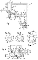
- FIG. 1 shows a section of a vial machine 1 in a position at the beginning of a mouth formation.
- the vial machine 1 has, as a base body, a carousel 2, which is also only partially shown here, and which carries rotatable receiving devices 4 (only one is shown) over the outer periphery of an upper level 3 at regular intervals for each glass tube 5.
- a carriage 7 is seated on a middle plane 6 and is guided 50 by rails 8 on rollers.
- the rail guide is aligned radially to the longitudinal axis LA of the glass tube 5.
- a cylinder 9 is fastened such that a piston 10 which is displaceably arranged in the cylinder 9 is aligned longitudinally to the longitudinal axis LA of the glass tube 5.
- a shaping finger 11 is attached to the upper end of the piston 10.
- the carriage 7 is displaceable via a lever transmission 12 by means of a piston-cylinder combination 13.
- a piston-cylinder combination 13 For this purpose, the upper end of a long lever 14 is articulated on the rear end of the slide 7 and the lower end of the long lever 14 is articulated on a compensating piece 15, which in turn is articulated on the carousel 2.
- the piston-cylinder combination 13 is also articulated with its cylinder-side end to the carousel 2 and acts on the central region of the long lever 14 via a swivel joint 16 connected to the piston 17.
- the piston-cylinder combination 13 can be actuated hydraulically or pneumatically.
- the piston-cylinder combination is depressurized, a tension spring 19 connected to the carousel 2 and acting on the long lever 14 then pulling back the carriage 7 and thereby pushing the piston 17 into the cylinder 18.
- the carriage 7 moves back towards the interior of the carousel up to a stop 20.
- the stop 20 has an actuator 21 with which the return path of the carriage 7 can be limited so that all parts carried by the carriage 7 come outside the area of action of the glass tube 5 and possibly also outside of its receiving devices.
- the piston-cylinder combination 13 is acted upon, for example, with compressed air, as a result of which the piston 17 extends and displaces the carriage 7 with the shaping finger 11 in the direction of the longitudinal axis LA of the glass tube 5.
- the rail 50 is mounted radially to the longitudinal axis LA of the glass tube 5 or the receiving device 4. So that the form finger 11 or the piston 10 to which it is attached, exactly on the Longitudinal axis LA of the glass tube 5 comes, a stop 22 is provided on the middle level 6, which acts via an actuator 23 on an abutment 24 connected to the carriage 7. With the actuator 23, the piston 10 can be adjusted with the form finger 11 exactly on the longitudinal axis LA.
- the slide 27 As soon as the slide 27 has reached its outer end position and has thus brought the form finger 11 onto the longitudinal axis LA, it can be pushed into the lower end 25 of the glass tube by means of the piston 10.
- the cylinder 9 is connected to a fluid, e.g. Pressurized air, whereby the piston 10 extends until an abutment 27 strikes an actuator 28, which is set so that the forming finger 11 is at a desired height with respect to the lower glass tube end 25 and a forming roller 29. In this position, the form roller 29 can then roll the lower glass tube end 25 against the form finger 11.
- the abutment 27 simultaneously prevents the form finger 11 from rotating with the rotated glass tube 5.
- the molding finger 11 can be pulled out of the now shaped glass tube end 25 via the piston 10 by applying negative pressure to the cylinder 9 or, if desired, also via a tension spring (not shown) and can be moved back as described to the interior of the carousel.
- the shaped finger 11 can be designed as a normal cylinder, but an embodiment of the shaped finger 11, as shown in FIG. 2a, is advantageous.
- This form finger 11 is part of an originally cylindrical form 30, on which approx. 40% of the rear area 31 and each approx. 7% of the lateral areas 32 (the percentages relate to the original diameter of the cylindrical form 30) were milled off. This creates a cylinder cutout, as shown in cross section in FIG. 2a.
- This shaping finger 11 has a circular section area 33, which still has the original function of the shaping finger, namely the smoothing and support (shaping) of the interior of the mouth to be shaped.
- the circular section area 33 covers an angle of approximately 130 ° at which the shaping roller 29 can start and form. Corresponding to the angle of 130 °, the circular section area 33 has an arc length of 2.r. ⁇ .130 ° / 360 °, where r is the radius of the circular section area. Forming can no longer take place on the other sides of the forming finger 11, this forming finger 11 is therefore only intended for use in vial machines with one forming roller per forming station (as shown, for example, in FIG. 1).
- the area of approx. 130 ° of a full cylinder covered by the circular section area 33 depends on the structural conditions of a vial machine or molding station used in each case.
- the molding finger is to be formed by 180 ° or more, only the rear area 31 is to be removed from a solid cylinder. Normally, however, a circular section area 33 of less than 180 ° is sufficient and also desirable, because of the decrease in the rear area 31 and lateral areas 32, the cross section of the shaped finger is reduced so that it can be pulled out of this easily and even without touching the inner circumference of a finished mouth.
- Figure 2b shows a shaped finger 11, the cross section of which has a D 2h symmetry. Compared to the cylindrical shape 30, only the lateral areas 32 are milled free.
- This form finger 11 has two circular section areas 33 with an angle of approximately 135 ° in each case and is used in a formation with two form rollers or in a movable mounting of the form finger (described below).
- a support 34 can be provided for a mouth edge to be shaped.
- This support 34 has essentially the shape of a cylindrical disk 35 with a larger diameter than the cylindrical shape 30 and is arranged concentrically to this.
- the cylindrical disk 35 has a recess 36 below the circular section area 33, which forms a free space for the form roller 29, so that it can penetrate closer to the form finger 11 than is the nominal dimension of the rolled edge outer diameter of a vial to be shaped.
- FIG. 4 Such a situation is shown in Figure 4.
- the cylindrical disc 35 is attached to the piston 10 at 37 (eg by means of a screw).
- An oil drip pan 38 is arranged between the piston 10 and the cylindrical disk 35, which collects molding oil sprayed over the molding finger 11 and returns it via an outlet 39.
- the support 34 has a surface 40 that slopes towards the center of the shaping finger and that forms the upper edge of a vial mouth 41.
- the bevel has an angle of 5 ° and depends on the intended use of the vial to be manufactured.
- the molding oil can run off over the entire molding finger 11 and the cylindrical disk 35, or can also be discharged through channels 42 through the cylindrical disk.
- the turned glass tube 5 is pressed at its end 25 against the circular section region 33 of the molding finger 11 by means of the molding roller 29.
- the form roller 29 has on its edge a profile 43, the outwardly projecting part 44 presses the glass tube end 25 against the circular section area 33 and thereby forms a bottle neck 45.
- a somewhat thicker glass bead is formed in front of an inwardly projecting part 46 of the profile 43 and is formed into a flanged or rolled edge 47 in contact with the circular section region 33 and the inclined surface 40.
- the shaping roller 29 can penetrate somewhat closer to the shaping finger 11 in the region of the recess 36, so that a small glass item 48 is pressed into the free space formed by the recess 36.
- an enlarged rim 49 or collar can be provided at the upper end of the shaping finger 11, which collar forms an undercut in the vial neck 45.
- this shaping finger 11 must either be displaced radially or pulled out obliquely from the finished vial mouth 41.
- Such a pulling out of the shaped finger is also useful if no enlarged edge 49 is provided, since in this case the circular section area 33 is removed from the mouth without touching the inner wall thereof.
- the rear area and the lateral areas can also be removed, for example in the manner of an oval, differently than shown.
- the largest possible cross-sectional area of the forming finger should remain so that the heat absorbed at the circular section area can be dissipated quickly.
- FIG. 5 shows a form finger arrangement similar to that in FIG. 1, but with other displacement means, with which the same function is achieved as in FIG. 1, and a different form finger suspension.
- the shaped finger 11 is fastened here to the upper end of a holding pin 51, the lower end of which is seated in a spherical bearing 52.
- the articulated bearing 52 allows the holding pin 51 to be swiveled horizontally with the form finger 11 fastened thereon. This horizontal swiveling movement is limited by a bearing part 53, at the lower end of which the articulated bearing 52 sits and which has a bore 54 in which the holding pin 51 with approximately ⁇ 0.5 mm clearance.
- a locking pin 55 is inserted into the spherical bearing 52, which permits pivoting of the spherical bearing 52 and thus also of the shaped finger 11 in the horizontal plane, but prevents twisting.
- a drop of molding oil is placed on the upper end 56, which on the one hand prevents the molding finger from sticking to the heat-softened glass of the glass tube 5 and also contributes to cooling the molding finger 11.
- the molding oil can flow off over the surface of the molding finger 11 and over the cylindrical disk 35 arranged below the molding finger 11 and drips over a pointed edge 57 into an annular oil collecting trough 58 and from there via the oil drain 39 at a central location (not shown) ) to be collected.
- the radially movable form finger 11 is vertically displaceable via the bearing part 53.
- the bearing part 53 sits with a dovetail 59 arranged parallel to the bore 54 in a dovetail guide 60 and can be raised and lowered again vertically by means of a roller 61 via a curve 62.
- a horizontal slide 63 is provided which carries the dovetail guide 60 on its end face 64 and is itself held by a carrier part 65 which is connected to the middle plane 6 of the carousel 2.
- Two linear roller guides 66 are arranged between the carrier part 65 and the horizontal slide 63, which allow the shaping finger 11 to be displaced from its rest position to the longitudinal axis LA of the glass tube 5. The displacement takes place via a curve 67 which guides a roller 68 connected to the horizontal slide 63.
- the horizontal carriage 63 can be returned either by means of a return spring (not shown) or via a further curve (not shown).
Claims (18)
- Dispositif (1) pour le formage d'une zone d'embouchure sur une extrémité (25) ouverte, ramollie par la chaleur, d'un tube de verre (5), comprenant un carrousel (2) qui porte une multitude de tubes de verre susceptibles de tourner autour de leur propre axe longitudinal (LA) et fait passer ces tubes, à des intervalles égaux les uns des autres, sur une trajectoire commune à un poste de formage auquel les extrémités des tubes de verre sont roulées successivement au moyen d'un galet de formage (29), et des doigts de formage (11) gui peuvent être engagés dans les extrémités ramollies des tubes de verre en vue du formage et être ensuite retirés de ces extrémités et qui sont prévus pour soutenir les extrémités des tubes de verre pendant l'opération de roulage, un doigt de formage étant associé à chaque tube de verre et chaque doigt de formage étant disposé sur le carrousel, caractérisé par le fait que chaque doigt de formage (11) est monté sur deux chariots (7, 10) à l'aide desquels le doigt de formage (11) est déplaçable en translation aussi bien radialement qu'en direction longitudinale par rapport à l'axe longitudinal (LA) du tube de verre (5) associé.
- Dispositif suivant la revendication 1, caractérisé par le fait que le doigt de formage (11) se trouve dans l'une des positions extrêmes de l'un des chariots (7) sur l'axe longitudinal (LA) du tube de verre associé (5) et dans l'une des positions extrêmes de l'autre chariot (10) à l'intérieur de l'extrémité (25) du tube de verre, au niveau du galet de formage (29).
- Dispositif suivant la revendication 1 ou 2, caractérisé par le fait que le doigt de formage (11) présente un jeu horizontal.
- Dispositif suivant la revendication 3, caractérisé par le fait que le doigt de formage (11) est disposé sur un palier d'articulation ou à rotule (52).
- Dispositif suivant la revendication 4, caractérisé par le fait que le doigt de formage (11) est monté sur une extrémité d'un axe de support (51) dont l'extrémité inférieure est reliée au palier d'articulation (52).
- Dispositif suivant la revendication 5, caractérisé par le fait que l'axe de support (51) est disposé dans un guide (54) en vue de la limitation de son rayon de pivotement.
- Dispositif suivant l'une des revendications 3 à 6, caractérisé par le fait que le doigt de formage présente une liberté de mouvement horizontal de ± 1,0 mm au maximum, de préférence jusqu'à ± 0,5 mm.
- Dispositif suivant la revendication 7, caractérisé par le fait que la partie de palier (53) est disposée par une glissière (59, 60) sur le côté frontal d'un chariot horizontal (63).
- Dispositif suivant l'une des revendications 3 à 8, caractérisé par le fait qu'une cuvette de récupération d'huile (58) avec une sortie d'évacuation d'huile (39) est prévue en dessous du doigt de formage (11).
- Dispositif suivant l'une des revendications 3 à 9, caractérisé par le fait que le doigt de formage (11) présente la forme d'un cylindre comportant des méplats opposés entre lesquels subsistent deux zones (33) en segment de cercle de 100° à 150°.
- Dispositif suivant l'une des revendications 1 à 10, caractérisé par le fait que le doigt de formage (11) présente au moins une zone (33) en segment de cercle qui entre en contact avec un pourtour intérieur de la zone d'embouchure et détermine le rayon intérieur de l'embouchure (41), et que le doigt de formage (11) présente un rapport de sa section par la longueur d'arc de sa zone (33) en segment de cercle supérieur ou égal à 0,55.r, r étant le rayon de la zone (33) en segment de cercle.
- Dispositif suivant la revendication 11, caractérisé par le fait que la section du doigt de formage (11) est supérieure ou égale à 0,5.r².π.
- Dispositif suivant la revendication 11 ou 12, caractérisé par le fait que la zone (33) en segment de cercle s'étend sur 60° à 190° d'un cylindre.
- Dispositif suivant la revendication 13, caractérisé par le fait que la zone (33) en segment de cercle s'étend sur 100° à 150°.
- Dispositif suivant l'une des revendications 11 à 14, caractérisé par le fait que le doigt de formage (11) présente un disque cylindrique (35) qui est disposé concentriquement à la zone (33) en segment de cercle, qui sert d'appui (34) pour l'extrémité (25) du tube de verre et qui présente une surface périphérique circulaire dont le rayon est supérieur au rayon de la zone (33) en segment de cercle.
- Dispositif suivant la revendication 15, caractérisé par le fait que l'appui (34) présente une surface en pente descendante vers le centre.
- Dispositif suivant la revendication 15 ou 16, caractérisé par le fait que la surface périphérique présente une échancrure (35) dans la zone opposée au galet de formage (29).
- Dispositif suivant l'une des revendications 11 à 17, caractérisé par le fait que le doigt de formage (11) présente un bord (49) faisant saillie vers l'extérieur à l'extrémité supérieure de sa zone (33) en segment de cercle.
Priority Applications (1)
| Application Number | Priority Date | Filing Date | Title |
|---|---|---|---|
| EP95109973A EP0678481A2 (fr) | 1990-09-11 | 1991-08-16 | Doigt pour la formation du col d'une fiole en verre |
Applications Claiming Priority (2)
| Application Number | Priority Date | Filing Date | Title |
|---|---|---|---|
| DE4028823 | 1990-09-11 | ||
| DE4028823A DE4028823C2 (de) | 1990-09-11 | 1990-09-11 | Vorrichtung und Formfinger zum Formen eines Mündungsbereiches an einem Glasfläschchen |
Related Child Applications (2)
| Application Number | Title | Priority Date | Filing Date |
|---|---|---|---|
| EP95109973.8 Division-Into | 1991-08-16 | ||
| EP95109973A Division-Into EP0678481A2 (fr) | 1990-09-11 | 1991-08-16 | Doigt pour la formation du col d'une fiole en verre |
Publications (3)
| Publication Number | Publication Date |
|---|---|
| EP0475112A2 EP0475112A2 (fr) | 1992-03-18 |
| EP0475112A3 EP0475112A3 (en) | 1993-01-20 |
| EP0475112B1 true EP0475112B1 (fr) | 1996-02-21 |
Family
ID=6414041
Family Applications (2)
| Application Number | Title | Priority Date | Filing Date |
|---|---|---|---|
| EP91113745A Expired - Lifetime EP0475112B1 (fr) | 1990-09-11 | 1991-08-16 | Appareil pour la formation du col d'une petite bouteille en verre |
| EP95109973A Ceased EP0678481A2 (fr) | 1990-09-11 | 1991-08-16 | Doigt pour la formation du col d'une fiole en verre |
Family Applications After (1)
| Application Number | Title | Priority Date | Filing Date |
|---|---|---|---|
| EP95109973A Ceased EP0678481A2 (fr) | 1990-09-11 | 1991-08-16 | Doigt pour la formation du col d'une fiole en verre |
Country Status (6)
| Country | Link |
|---|---|
| US (1) | US5252115A (fr) |
| EP (2) | EP0475112B1 (fr) |
| JP (1) | JPH04231333A (fr) |
| CA (1) | CA2051184A1 (fr) |
| DE (2) | DE4028823C2 (fr) |
| ES (1) | ES2083492T3 (fr) |
Families Citing this family (10)
| Publication number | Priority date | Publication date | Assignee | Title |
|---|---|---|---|---|
| DE102004014170B3 (de) * | 2004-03-17 | 2005-10-27 | Ambeg - Dr. J. Dichter Gmbh | Glasbearbeitungsmaschine und Steuerungsverfahren hierfür |
| JP5238255B2 (ja) * | 2004-09-30 | 2013-07-17 | ベクトン・ディキンソン・アンド・カンパニー | ガラス製容器内の残留物を削減又は除去するための方法及びそれにしたがって製造されたガラス製容器 |
| DE102016123865A1 (de) | 2016-12-08 | 2018-06-14 | Schott Ag | Verfahren zum Weiterverarbeiten eines Glasrohr-Halbzeugs einschließlich einer thermischen Umformung |
| DE102016124833A1 (de) | 2016-12-19 | 2018-06-21 | Schott Ag | Verfahren zum Herstellen eines Hohlglasprodukts aus einem Glasrohr-Halbzeug mit Markierungen, sowie Verwendungen hiervon |
| DE102016125129A1 (de) | 2016-12-21 | 2018-06-21 | Schott Ag | Verfahren zum Herstellen eines Glasrohr-Halbzeugs oder eines daraus hergestellten Hohlglasprodukts mit Markierungen, sowie Verwendungen hiervon |
| US11186513B2 (en) | 2017-11-30 | 2021-11-30 | Corning Incorporated | Systems and methods for minimizing SHR from pharmaceutical part converting using negative pressure evacuation |
| US11339079B2 (en) | 2017-11-30 | 2022-05-24 | Corning Incorporated | Systems and methods for minimizing SHR from pharmaceutical part converting using pulsed ejection |
| US11420893B2 (en) | 2017-11-30 | 2022-08-23 | Corning Incorporated | Systems and methods for minimizing SHR from piercing during pharmaceutical part converting using a gas flow |
| US10968133B2 (en) | 2017-11-30 | 2021-04-06 | Corning Incorporated | Methods for minimizing SHR in glass articles by producing a gas flow during pharmaceutical part converting |
| DE102018126053A1 (de) * | 2018-10-19 | 2020-04-23 | Schott Schweiz Ag | Verfahren und Vorrichtung zur Heißumformung von gläsernen Werkstücken und heißumgeformte Glasbehälter |
Family Cites Families (11)
| Publication number | Priority date | Publication date | Assignee | Title |
|---|---|---|---|---|
| US416559A (en) * | 1889-12-03 | beady | ||
| CA581053A (fr) * | 1959-08-11 | C. Kahle Louis | Methode et appareil pour la production d'articles de verre | |
| US1006383A (en) * | 1910-12-29 | 1911-10-17 | Robert Johns | Neck-grooving attachment for bottle-molding machines. |
| US1229028A (en) * | 1913-09-06 | 1917-06-05 | Louis Naglee Bruner | Apparatus for use in the manufacture of glass bottles and the like. |
| US3449105A (en) * | 1966-03-11 | 1969-06-10 | Corning Glass Works | Flexible shaping tool |
| DE1596410B2 (de) | 1966-11-29 | 1976-07-15 | Dichter, Hans-Joachim, 1000 Berlin | Kontinuierlich arbeitende maschine zum herstellen von flaeschchen, ampullen o.dgl. aus thermoplastischem material, insbesondere glas |
| US4284447A (en) * | 1976-02-20 | 1981-08-18 | Dickens Luther I | Method of manufacturing a composite panel |
| IT1120161B (it) * | 1979-11-27 | 1986-03-19 | Ermanno Vertova | Metodo e macchina per la formazione di fiale ottenute da tubo di vetro |
| US4441908A (en) * | 1981-03-30 | 1984-04-10 | Owens-Illinois, Inc. | Vial tooling apparatus |
| CH663408A5 (en) * | 1984-03-02 | 1987-12-15 | Owens Illinois Inc | Machine for working regions of preforms made of thermoplastic material |
| DE8610713U1 (fr) * | 1986-04-17 | 1987-08-20 | Dichter, Hans-Joachim, 1000 Berlin, De |
-
1990
- 1990-09-11 DE DE4028823A patent/DE4028823C2/de not_active Expired - Fee Related
-
1991
- 1991-08-16 ES ES91113745T patent/ES2083492T3/es not_active Expired - Lifetime
- 1991-08-16 DE DE59107422T patent/DE59107422D1/de not_active Expired - Fee Related
- 1991-08-16 EP EP91113745A patent/EP0475112B1/fr not_active Expired - Lifetime
- 1991-08-16 EP EP95109973A patent/EP0678481A2/fr not_active Ceased
- 1991-09-10 US US07/756,845 patent/US5252115A/en not_active Expired - Fee Related
- 1991-09-11 CA CA002051184A patent/CA2051184A1/fr not_active Abandoned
- 1991-09-11 JP JP3258688A patent/JPH04231333A/ja active Pending
Also Published As
| Publication number | Publication date |
|---|---|
| US5252115A (en) | 1993-10-12 |
| EP0678481A3 (fr) | 1995-11-22 |
| DE4028823C2 (de) | 1994-07-07 |
| CA2051184A1 (fr) | 1992-03-12 |
| EP0678481A2 (fr) | 1995-10-25 |
| JPH04231333A (ja) | 1992-08-20 |
| EP0475112A2 (fr) | 1992-03-18 |
| DE4028823A1 (de) | 1992-03-12 |
| EP0475112A3 (en) | 1993-01-20 |
| DE59107422D1 (de) | 1996-03-28 |
| ES2083492T3 (es) | 1996-04-16 |
Similar Documents
| Publication | Publication Date | Title |
|---|---|---|
| DE4028824C1 (fr) | ||
| EP0630734B1 (fr) | Procédé de démoulage de corps creux moulés par injection avec des contre-dépouilles dans le contour interne et noyau associé | |
| EP0475112B1 (fr) | Appareil pour la formation du col d'une petite bouteille en verre | |
| DD270505A5 (de) | Verfahren und vorrichtung zur ausbildung eines behaelters | |
| DE19914974C2 (de) | Wechselcorrugator | |
| DE3623099C2 (de) | Blasformmaschine | |
| DE2830150C2 (de) | Vorrichtung zum Herstellen von Formkörpern aus thermoplastischem Kunststoff | |
| DE2324953A1 (de) | Formstation zur herstellung von hohlglasgegenstaenden | |
| EP0034267B1 (fr) | Machine pour fabriquer des corps creux soufflés en matière plastique | |
| DE1596650B2 (de) | Maschine zur herstellung von flaeschchen aus glasrohren | |
| EP1129039A1 (fr) | Procede et dispositif pour presser une ebauche | |
| DE2609651C2 (de) | Formwerkzeug für schmelzflüssiges Gas | |
| WO1996035529A1 (fr) | Procede pour la formation d'une zone retrecie et bordee sur un corps creux cylindrique, et dispositif pour la mise en ×uvre de ce procede | |
| EP1377424B1 (fr) | Procede de formage de matiere thermoplastique | |
| DE1652657B2 (de) | Walzvorrichtung zum kaltwalzen von relativ duennwandigen lagerlaufringen | |
| EP2165785B1 (fr) | Dispositif et procédé de fabrication de rainures longitudinales dans des pièces usinées cylindriques | |
| DE2035926B2 (de) | Verfahren und vorrichtung zum einbringen eines glastropfens in eine form | |
| DE19728669A1 (de) | Verfahren und Querwalzmaschine zum Formen eines rotationssymmetrischen Hohlkörpers | |
| EP0734837A1 (fr) | Dispositif pour transporter une paraison d'une filière annulaire au moule de soufflage d'une machine de moulage par soufflage | |
| DE1596650C3 (de) | Maschine zur Herstellung von Fläschchen aus Glasrohren | |
| DE4132216C1 (en) | Glass bottle base forming station - has carousel with rail parallel to circular track and carries carriage to which base forming plate is fastened | |
| EP1136225A2 (fr) | Moule d'injection et procédé de fabrication du moule intérieur | |
| DE2460184B2 (de) | Einrichtung zum Anformen einer glatten nach innen gewölbten Randrille am offenen Ende eines metallischen Behälters | |
| DE3112136A1 (de) | Werkzeug zum inneren abstuetzen des bettes einer einteiligen tiefbettfelge | |
| DE1173866B (de) | Maschine zur Herstellung von Verschlusskappen mit elastischer Dichtung |
Legal Events
| Date | Code | Title | Description |
|---|---|---|---|
| PUAI | Public reference made under article 153(3) epc to a published international application that has entered the european phase |
Free format text: ORIGINAL CODE: 0009012 |
|
| AK | Designated contracting states |
Kind code of ref document: A2 Designated state(s): BE CH DE ES FR GB IT LI |
|
| PUAL | Search report despatched |
Free format text: ORIGINAL CODE: 0009013 |
|
| AK | Designated contracting states |
Kind code of ref document: A3 Designated state(s): BE CH DE ES FR GB IT LI |
|
| 17P | Request for examination filed |
Effective date: 19930216 |
|
| 17Q | First examination report despatched |
Effective date: 19940606 |
|
| GRAA | (expected) grant |
Free format text: ORIGINAL CODE: 0009210 |
|
| AK | Designated contracting states |
Kind code of ref document: B1 Designated state(s): BE CH DE ES FR GB IT LI |
|
| XX | Miscellaneous (additional remarks) |
Free format text: TEILANMELDUNG 95109973.8 EINGEREICHT AM 16/08/91. |
|
| ET | Fr: translation filed | ||
| REF | Corresponds to: |
Ref document number: 59107422 Country of ref document: DE Date of ref document: 19960328 |
|
| GBT | Gb: translation of ep patent filed (gb section 77(6)(a)/1977) |
Effective date: 19960229 |
|
| REG | Reference to a national code |
Ref country code: ES Ref legal event code: FG2A Ref document number: 2083492 Country of ref document: ES Kind code of ref document: T3 |
|
| ITF | It: translation for a ep patent filed |
Owner name: STUDIO TORTA SOCIETA' SEMPLICE |
|
| PLBE | No opposition filed within time limit |
Free format text: ORIGINAL CODE: 0009261 |
|
| STAA | Information on the status of an ep patent application or granted ep patent |
Free format text: STATUS: NO OPPOSITION FILED WITHIN TIME LIMIT |
|
| 26N | No opposition filed | ||
| PGFP | Annual fee paid to national office [announced via postgrant information from national office to epo] |
Ref country code: GB Payment date: 19970716 Year of fee payment: 7 |
|
| PGFP | Annual fee paid to national office [announced via postgrant information from national office to epo] |
Ref country code: FR Payment date: 19970717 Year of fee payment: 7 |
|
| PGFP | Annual fee paid to national office [announced via postgrant information from national office to epo] |
Ref country code: BE Payment date: 19970723 Year of fee payment: 7 |
|
| PGFP | Annual fee paid to national office [announced via postgrant information from national office to epo] |
Ref country code: DE Payment date: 19970804 Year of fee payment: 7 Ref country code: CH Payment date: 19970804 Year of fee payment: 7 |
|
| PGFP | Annual fee paid to national office [announced via postgrant information from national office to epo] |
Ref country code: ES Payment date: 19970829 Year of fee payment: 7 |
|
| PG25 | Lapsed in a contracting state [announced via postgrant information from national office to epo] |
Ref country code: GB Free format text: LAPSE BECAUSE OF NON-PAYMENT OF DUE FEES Effective date: 19980816 |
|
| PG25 | Lapsed in a contracting state [announced via postgrant information from national office to epo] |
Ref country code: ES Free format text: LAPSE BECAUSE OF NON-PAYMENT OF DUE FEES Effective date: 19980817 |
|
| PG25 | Lapsed in a contracting state [announced via postgrant information from national office to epo] |
Ref country code: LI Free format text: LAPSE BECAUSE OF NON-PAYMENT OF DUE FEES Effective date: 19980831 Ref country code: CH Free format text: LAPSE BECAUSE OF NON-PAYMENT OF DUE FEES Effective date: 19980831 Ref country code: BE Free format text: LAPSE BECAUSE OF NON-PAYMENT OF DUE FEES Effective date: 19980831 |
|
| BERE | Be: lapsed |
Owner name: SCHOTT GLASWERKE Effective date: 19980831 |
|
| GBPC | Gb: european patent ceased through non-payment of renewal fee |
Effective date: 19980816 |
|
| REG | Reference to a national code |
Ref country code: CH Ref legal event code: PL |
|
| PG25 | Lapsed in a contracting state [announced via postgrant information from national office to epo] |
Ref country code: FR Free format text: LAPSE BECAUSE OF NON-PAYMENT OF DUE FEES Effective date: 19990430 |
|
| PG25 | Lapsed in a contracting state [announced via postgrant information from national office to epo] |
Ref country code: DE Free format text: LAPSE BECAUSE OF NON-PAYMENT OF DUE FEES Effective date: 19990601 |
|
| REG | Reference to a national code |
Ref country code: FR Ref legal event code: ST |
|
| REG | Reference to a national code |
Ref country code: ES Ref legal event code: FD2A Effective date: 19990910 |
|
| PG25 | Lapsed in a contracting state [announced via postgrant information from national office to epo] |
Ref country code: IT Free format text: LAPSE BECAUSE OF NON-PAYMENT OF DUE FEES;WARNING: LAPSES OF ITALIAN PATENTS WITH EFFECTIVE DATE BEFORE 2007 MAY HAVE OCCURRED AT ANY TIME BEFORE 2007. THE CORRECT EFFECTIVE DATE MAY BE DIFFERENT FROM THE ONE RECORDED. Effective date: 20050816 |