EP0475047A2 - Apparatus and method for transforming the heated end of a glass tube and application of the said apparatus in a machine for making small bottles - Google Patents
Apparatus and method for transforming the heated end of a glass tube and application of the said apparatus in a machine for making small bottles Download PDFInfo
- Publication number
- EP0475047A2 EP0475047A2 EP91112647A EP91112647A EP0475047A2 EP 0475047 A2 EP0475047 A2 EP 0475047A2 EP 91112647 A EP91112647 A EP 91112647A EP 91112647 A EP91112647 A EP 91112647A EP 0475047 A2 EP0475047 A2 EP 0475047A2
- Authority
- EP
- European Patent Office
- Prior art keywords
- glass tube
- roller
- form roller
- chuck
- shaping
- Prior art date
- Legal status (The legal status is an assumption and is not a legal conclusion. Google has not performed a legal analysis and makes no representation as to the accuracy of the status listed.)
- Granted
Links
Images

Classifications
-
- C—CHEMISTRY; METALLURGY
- C03—GLASS; MINERAL OR SLAG WOOL
- C03B—MANUFACTURE, SHAPING, OR SUPPLEMENTARY PROCESSES
- C03B23/00—Re-forming shaped glass
- C03B23/04—Re-forming tubes or rods
- C03B23/09—Reshaping the ends, e.g. as grooves, threads or mouths
- C03B23/095—Reshaping the ends, e.g. as grooves, threads or mouths by rolling
-
- C—CHEMISTRY; METALLURGY
- C03—GLASS; MINERAL OR SLAG WOOL
- C03B—MANUFACTURE, SHAPING, OR SUPPLEMENTARY PROCESSES
- C03B23/00—Re-forming shaped glass
- C03B23/04—Re-forming tubes or rods
- C03B23/11—Reshaping by drawing without blowing, in combination with separating, e.g. for making ampoules
- C03B23/112—Apparatus for conveying the tubes or rods in a curved path around a vertical axis through one or more forming stations
Definitions
- the invention relates to a device for deforming the end region of a glass tube to form a mouth region of a vial according to the preamble of claim 1, a method for forming a vial and the use of the device in a vial machine.
- DE-PS 12 61 638 describes a known device of this type, in which a ring of holding devices rotates workpieces in the form of glass tubes in a workpiece path past at least one processing station.
- the processing station contains swiveling cantilever arms, which carry shaping parts.
- the shaping parts are pivoted into the workpiece path and can form the workpieces on a section of the workpiece path, the section being severely limited by the size and arrangement of the cantilever arms.
- the ring with the workpieces must either be stopped during the shaping, or may only rotate very slowly, or the shaping process is divided into several individual shaping processes, which in turn creates a multiplicity of processing stations for the Machining the same place on the vial becomes necessary.
- the cantilever arm must be swiveled back quickly into the starting position after the shaping in order to have more time available for the shaping. This leads to increased mechanical stress and correspondingly increased wear.
- the shaping rollers In order to enlarge the section on which the shaping takes place, the shaping rollers have been placed in a device known from DE-PS 15 96 410 on a transport device, which for the duration of the shaping with the angular speed of the ring with the workpieces and parallel travels to the workpieces so that the workpiece to be shaped is stationary with respect to the transport device.
- the transport device In order to form the subsequent workpiece during the return of the transport device, several transport devices with shaping rollers must be used, the transport device e.g. can be connected to one another via a chain, so that while the first transport device moves back, another transport device for shaping moves alongside the subsequent workpiece.
- each transport device has a processing break of at least 100% of the forming time of a vial. Tolerances of the individual transport devices and the shaping rollers result in slightly different vial types in this device, depending on the number of transport devices.
- the invention has for its object to provide a device for the production of hollow bodies from glass tubes, wherein no or only short processing breaks should occur and a high production speed should be possible.
- the mechanical effort for the processing station should be as low as possible in order to obtain low tolerances in the vials produced.
- a vial machine can process glass tubes with different wall thicknesses or outside diameters without the need for lengthy conversion work or adjustment work.
- the object of the invention is also a method for producing a vial.
- the invention enables mass production of uniform vials without high mechanical stress on the shaping parts.
- vial stands for all hollow bodies that can be produced from a tube, e.g. Rolled-edge vials, snap-lid jars, ampoules etc. It has been shown that by means of the form roller, which can be pushed back and forth relative to the passing glass tube and which simply evades the glass tube by rolling it back and forth during shaping, the idle times of the shaped parts can be minimized and even completely avoided since the form roller is in the start position for the shaping of the subsequent glass tube towards the end of the curling. This enables the carousel to be continuously rotated at a considerable speed and thus a continuous mass production of the hollow bodies at a high production speed.
- a particular advantage of the invention is that the back and forth movement of the form roller is controlled with little effort by means of a fine drive and a programmable control device can be changed so that the shaping parameters can be easily changed and adapted to other conditions, such as other glass tube diameters.
- the form roller is moved on a straight line, so that the mechanical outlay is particularly low.
- Hollow bodies such as e.g. Vials, ampoules, candle lamps, etc. are formed from glass tubes, which can be passed by the device according to the invention in rotatable holding chucks on a runway, in particular in a carousel.
- the axis of the form roller is substantially parallel to the glass tube axis, so that the shape roller always attaches to the part of the glass tube to be deformed at the same height during shaping.
- the shaping roller can also be placed slightly obliquely against the glass tube.
- the form roller device is advantageously arranged stationary in relation to the run-out path of the holding chuck and is movable in a direction essentially transverse to the direction of the run-off path of the holding chuck, a phase shift preferably being set between the periodic reciprocating movement of the form roll and the periodic sequence of the holding chuck moving past becomes.
- This makes it possible to change the distance of the point of the form roller circumference closest to a chuck axis from this chuck axis during the relative arc movement of the form roller around the chuck axis with simultaneous use of up to 100% of the duration of a periodic sequence as the form time.
- the inclined position is particularly advantageous in the case of a circular running path of the holding chuck, in which case the inclined position can be achieved simply by horizontally displacing the slide rail of the form roller from a radial of the circular path in the direction of the running path.
- the degree of displacement is determined from the dimensions of the vial machine and the vials, such as the radii of the carousel, the glass tube, the form roller, the shaped mouth and the angle of rotation of the carousel, through which the shaping takes place.
- the inclined angle deviates only a few degrees from the vertical (transverse) angle, angles of attack of 80 ° -90 °, advantageously 85 ° -90 °, having proven to be favorable for the molding process.
- the most suitable angle of attack, as described above, is 90 °.
- the holding chucks are advantageously arranged on a turntable which can be driven with a constant rotary movement, so that they describe a circular path, the tube axes preferably being parallel and at the same spacing from one another on a cylinder jacket.
- the individual steps such as inserting the glass tubes into the machine, are the individual ones Processing steps and further processing of the vial after the mouth is formed in a single, compact vial machine.
- the shaping roller device preferably has only a single shaping roller, the edge of which advantageously has a profile that forms the outside of the mouth section.
- a profile is also with e.g. two form rollers lying one above the other are possible, which roll on the glass tube at different distances with respect to the axis of rotation of the glass tube.
- the form roller in the interior of the glass tube end is advantageously supported by such a form finger, which has a smaller cross section than the desired inner cross section of the glass tube end to be shaped and is provided with a circular arc segment, which advantageously extends over at least the circumferential angle over which the form roller engages with rolls off the glass tube, the radius of the circular arc segment advantageously being equal to the radius of the desired inner cross section.
- a form finger is not in contact with the heat-softened glass over its entire circumference and can therefore be more easily removed from the finished mouth.
- the diameter of the form roller is chosen so that it is greater than the pitch between the chucks, reduced by the minimum processable glass tube radius plus reduced by the minimum Muzzle radius.
- a diameter of the form roller is chosen which is 30% to 100% larger than the pitch between the holding chucks, reduced by the minimally processable glass tube radius and reduced by the minimum mouth radius, which has a favorable characteristic of the back and forth movement of the form roller with practical results in all usable glass tube diameters.
- the form roller on the stationary support can be moved back and forth precisely on a slide, which can be moved with a servo motor via a guide axis control system in synchronism with the periodic sequence of the holding chucks moved past.
- This arrangement has proven to be particularly favorable given the precision of the shape described.
- Springing of the form roller is also advantageous, so that the shape roller acts elastically relative to the theoretical movement against the glass tube end to be deformed.
- This measure prevents destruction or excessive loading of mechanical parts if, for example, a hard, non-deformable object, such as a piece of glass, interferes with the shaping of the form roller.
- a hard, non-deformable object such as a piece of glass
- the accuracy of the device according to the invention could deteriorate due to the destruction or damage of certain mechanical components, such as, for example, the suspension of the form roller or the form finger.
- the springing serves as a safety element here.
- the springing also enables the processing of different glass masses (due to different glass tube qualities) in the mouth area, which means e.g. enlarged glass mass is evenly distributed over the mouth area so that a slightly larger, but circular outer diameter is created.
- the mouth region is expediently shaped with spring action, the spring not being in contact with a stop during the shaping.
- the object is achieved in that the form roller relative to the runway back and forth is moved with the periodicity of the glass tubes moving past, that the form roller is moved in an arc around this longitudinal axis relative to this longitudinal axis relative to this longitudinal axis relative to the longitudinal axis, which is closest to a longitudinal axis of a glass tube moving past, and that the form roller moves back from the run-off path of the glass tubes when a glass tube approaches and when the glass tube is removed, it is again moved against the run-off path into the
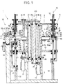
- a vial machine 1 which has an upper level 4 and a lower level 13.
- the levels 4 and 13 are firmly connected to one another and form a two-story carousel 2 which is mounted on a frame 3 via bearings 80.
- first receiving devices 5 are fastened at regular intervals about their own longitudinal axes, the lower ends of which each have a holding chuck 7 that can be opened and closed by means of a pneumatic cylinder 6.
- the level 4 has a diameter of approximately 80 cm (measured from the longitudinal axes AL of two opposing receiving devices 5) and carries 16 receiving devices 5.
- the diameter of the level 4 is preferably 60 cm to 120 cm, the The distance between two adjacent receiving devices 5 is advantageously from 11 cm to 23 cm.
- the pneumatic cylinder 6 pulls a fork 8 with two rollers 8a, which run in a circumferential groove 81 of a sliding sleeve 9, against a spring 10, as a result of which the sliding sleeve 9 pulls back clamping jaws 11 and releases a glass tube 12.
- pneumatic for example, electromagnetic and purely mechanical spring force controls controlled by curves are also possible. It is important that the chucks close softly so as not to destroy the glass tube. In principle, other types of suitable chucks are also suitable for holding the pipes.
- Glass tubes 12 with an outer diameter of 13 mm to 50 mm and with a wall thickness of 0.5 mm to 3.0 mm are particularly suitable for processing in the vial machine 1.
- the longitudinal axes AL of the first holding devices 5 run parallel to the carousel axis of rotation KD in the embodiment shown to simplify the construction.
- a second receiving device 14 which can also be rotated about its own longitudinal axis, is also arranged with a holding chuck 15 such that opposite first and second holding devices or their holding chucks each have a common longitudinal axis.
- the holding chucks 15 of the second holding devices 14 can be controlled via a curve (not shown), which acts from above on a cylinder 16 and via a fork with two rollers 86, which are guided in a groove 85 of a sliding sleeve 83, and thereby as above described, opens against a spring pressure 82 chuck 84 of the chuck 15.
- Pneumatic or electromagnetic actuation is also possible with the holding chuck 15, it is also decisive here that the holding chuck closes softly so as not to destroy the glass tube end or vial held by this chuck.
- a controllable motor 17 with an incremental encoder rotates the carousel 2 with the holding devices 5 and 14 via a pair of gears 18.
- a second motor 19, which can be controlled independently of the motor 17, is provided to rotate the holding devices 5 and 14 about their own axes of rotation AL a pair of gearwheels 20 (or a toothed belt drive, not shown), a tube 21 and a pair of gearwheels 22 (or directly with a chain (not shown) via a chain wheel 22a) act on a shaft 23, which has chain wheels 24 and 25 at their upper and lower ends has, via which the receiving devices 5 and 14 with sprockets 26 and 27 are driven in the same direction by means of chains, not shown, and with the same transmission ratio, so that the upper and lower receiving devices 5 and 14 rotate at the same speed.
- a lifting device 30 is provided, which is slidably arranged in a guide sleeve 29 and is guided via a wheel 31 over a curve 32.
- the height of the curve 32 can be made variable, so that the stroke of the second receiving device 14 can be adapted to a different working height for bottles of different lengths.
- a plurality of burners 33 are arranged below the first receiving devices 5, which heat a glass tube section 34 which is brought about and protrudes from the first receiving devices 5 to a temperature at which this can be separated from the glass tube 12 by train.
- a possibly closing glass tube end 38 is opened again by means of a puncture burner 57 (FIG. 3) and reheated by further burners (not shown).
- a forming station 35 which is arranged on a base 75 outside the carousel 2 and serves to form a mouth M into the glass tube ends 38.
- the shaping station 35 carries a shaping roller 36 which essentially has the shape of a disk and which can have a profile 37 on its periphery for shaping the mouth M into the glass tube end 38.
- the form roller 36 has a diameter which is greater than the distance between two successive glass tubes 12 and is guided so that it is in constant contact with a glass tube end 38, that is to say that the form roller 36 is practically constantly driven by a positively turned glass tube end 38 and therefore has no break from filming.
- the form roller 36 can be provided with a propeller 58, via which the form roller 36 can be driven by means of an air stream.
- the shaping roller 36 has a diameter of approximately 20 cm; diameters of 15 cm to 28 cm are generally favorable.
- a controllable and adjustable fine drive 39 with an incremental encoder is fastened to the forming station 35 and moves a slide 41, which is seated on a slide rail 42, via a threaded spindle 40.
- the forming roller 36 is rotatably mounted and adjusted to form the mouth at a suitable height to the glass tube end 38.
- the rotating glass tubes 12 are moved past the forming station 35 by rotating the carousel 2.
- the form roller 36 adapts to the circular path of the rotating glass tube 12 with a simultaneous rolling of the glass tube end 38 with a straight forward and backward movement, which runs essentially radially to the carousel 2.
- a transversal (secant) back and forth movement to the carousel 2 is also possible, the back and forth movement then being in a different phase shift to the periodic sequence of the passing chuck 7.
- the shaping roller 36 is preferably as far as the carousel rotation axis KD moved that the free space up to the subsequent glass tube end 38 is completely filled by the form roller 36, so that this can immediately begin with the formation of the subsequent glass tube end 38.
- the molding station 35 is aligned with respect to the carousel so that the back and forth movement of the molding roller 36 takes place radially to the carousel 2, as described above.
- the molding station 35 can then be firmly connected to the frame 3.
- a transverse guide 60 with respect to the carousel 2 is provided at the bottom of the base 75, in which the entire forming station 35 in a direction transverse to the slide rail 42 is movable.
- This shift can be done by hand, for example using a hand crank, advantageously however, this is done by means of a stepper motor 44, which acts on a toothed rack 46 via a gearwheel 45 and thereby shifts the molding station 35 in the tangential direction to the carousel 2 by a defined amount. It is important here that the transverse guide 60 is secured against inadvertent displacement during the molding process.
- this transverse (secant) back and forth movement to the carousel 2 and the associated phase shift to the periodic sequence of the passing chucks 7 can also be implemented by the software of the leading axis path control.
- a shaping finger 43 is provided which can be brought into the exact position under the center of the glass tube 12 and can be inserted into the glass tube end 38.
- the retracted form finger 43 forms an abutment for the heat-softened glass tube end 38 pressed in by the form roller 36, up to which the glass tube end 38 is rolled up.
- the distance between the wall of the shaping finger 43 facing the shaping roller 36 and the longitudinal axis of the glass tube 12 determines the inside diameter of the mouth to be shaped at the end of the glass tube 38.
- the shaped finger 43 preferably has a radius of 2 mm to 50 mm.
- each receiving device 5 has assigned a molding finger 43, which means more time for inserting and removing the molding finger 43 there is in the glass tube end 38 and the forming finger 38 also has sufficient time to cool down until the next molding operation.
- the shape finger 43 is slidably mounted in height on a horizontal slide 50 which can be pushed back and forth on a rail 52 via rollers 51.
- the rail 52 is fastened on a middle level 49 of the carousel 2.
- the form finger 43 By means of the horizontal slide 50, the form finger 43, which sits at the front end of the horizontal slide 50, can be displaced from a rest position A into the common longitudinal axis of the associated receiving devices 5 and 14. In this position B, the form finger 43 can be raised into the glass tube end 38 by means of a cam roller 54 guided by a cam 55.
- the horizontal slide 50 is preferably moved by means of compressed air via a pneumatic cylinder (not shown), which can be connected to the horizontal slide 50 either directly or preferably because of the small space available in radial expansion via a lever arrangement (not shown).
- the fully formed glass tube end 38c (FIG. 5) is cooled below the transformation temperature of the glass and dropped by opening the holding chuck 7 onto a baffle plate (not shown) which can be adjusted in the vertical direction according to the article length.
- the holding chuck 7 is closed again via cylinder 6.
- the second receiving device 14 arranged directly below the glass tube 12 is moved upward via the curve 32 to such an extent that the finished mouth M of the glass tube end 38 pushes a punch 47 against a spring 48 a little into the second receiving device 14.
- the lower holding chuck 15 is opened via the cylinder 16 and is closed again after the start-up via the same cylinder in order to grip the glass tube.
- the glass tube section 34 with the finished mouth M is, as described above, heated by the burner 33 to such an extent that it can be separated by pulling downwards.
- the severed glass tube section 34 closes at its upper end to form a vial preform.
- the upper glass tube 12 is further processed as described above and the separated glass tube section 34 moves further down in the second receiving device 14.
- the upper end of the separated glass tube section 34 is (not shown) Burner further heated and the vial preform formed into a finished vial 56 in a bottom molding step.
- the floor can be shaped by means of a floor forming station arranged outside the carousel, as described, for example, in DE-PS 12 61 638. As shown in FIG. 1, the bottom shaping can also be carried out particularly easily on the horizontal slide 50.
- a bottom former 53 which is normally a carbon compact, is arranged on each horizontal slide 50 below the forming finger 43. With this arrangement it is achieved that the bottom former 53 moves by means of the horizontal slide 50 together with the forming finger 43 into the common longitudinal axis of the holding devices 5 and 14 when the latter is inserted into the lower end 38 of the glass tube for the purpose of mouth formation. In this position of the bottom former 53, the associated lower receiving device 14 moves upwards over the curve 32 until the bottom 61 to be formed comes into contact with the bottom former 53.
- the above-described rotation of the second receiving device 14 results in a uniform bottom formation, with supporting air being blown into the inside of the vial against the bottom 61, especially in the case of glass tubes with a greater thickness (from approximately 15 mm outer diameter), so that this does not sag down, but comes into contact with the bottom former 53 with the entire bottom surface.
- the finished-shaped vial 56 is lowered again in the second receiving device 14 via the curve 32, so that the shaping finger 43, as described above, is also removed from the lower, now shaped glass tube end 38c can be extended.
- the floor former 53 then moves the form finger 43 back into its rest position A by means of the horizontal slide 50 in the direction of the axis of rotation KD of the carousel 2.
- the vial 56 is cooled, gripped in a subsequent station by a removal gripper in the bottom area and then released by opening and lowering the jaws 84 of the chuck 15.
- the empty holding chuck 15 is preferably automatically cleaned of any contaminants and then moved upwards to receive the next glass tube end 38, the forming process starting again.
- FIG 2 the structure of a molding station 35 is shown with further details.
- the base 75 of the molding station has at its foot the already mentioned transverse guide 60 and the toothed rack 46, by means of which the entire molding station 35 can be displaced in a direction transverse to the working movement of the molding roller 36.
- Via the transverse guide 60 it is possible to align the working movement of the shaping roller 36 exactly radially with respect to the axis of rotation of the carousel or, if desired, to offset it parallel to the radial, so that a transverse direction results.
- Such a transverse direction is preferably offset from the radial in the direction of rotation of the carousel.
- a threaded rod 62 is provided for moving the slide 41.
- the threaded rod 62 is rotatably supported at one end in the forming station base 75 and directly at its other end connected to the fine drive 39.
- the carriage 41 has a threaded passage 63 through which the threaded rod 62 is passed.
- the slide 41 can be correspondingly moved forwards or backwards along the slide rail 42.
- the slide rail 42 is either double or has a cross-section deviating from the circular, so that there is a stable guidance of the slide 41 and the threaded rod 62 is relieved of a lateral load by the slide 41.
- a spring is provided in the slide 41, which allows the form roller 36 to retreat if the pressure resistance is too high, for example a glass item that is not sufficiently heat-softened.
- the suspension is essentially carried out with a pneumatic cylinder 68, which displaces a carrier part 69 in the direction of the carousel 2.
- the carrier part 69 is held in a guide 70 in the slide 41, a stop 71 being provided so that the carrier part 69 is not pushed out of the slide 41 by the cylinder 68 if there is no resistance against the form roller 36. If the pressure resistance against the form roller 36 is too great, the latter can move back with the carrier part 69 against the cylinder 68 into an escape space 72, so that damage to the precision parts is avoided.
- the shaping roller 36 can adapt to fluctuating amounts of glass during the shaping of the mouth area and thus enables a circular outer diameter to be formed in the mouth area even with somewhat fluctuating glass thicknesses of the glass tube 12. Without this feathering Excessive amounts of glass are pushed between the forming finger 43 and the forming roller 36 during the forming, so that a circular outer diameter is also achieved here.
- a shaft 65 is attached, on which the form roller 36 is rotatably attached via a bearing 64.
- the axis of the shaft 65 is advantageously arranged parallel to the glass tube axes.
- the form roller 36 has on its edge the profile 37, the lower recess 66 of which forms a collar 67 at the mouth M.
- the height of the form roller 36 can be adjusted on the shaft 65 together with the bearing 64 or can be exchanged for a differently shaped form roller. This is necessary in order to adjust the height of the form rollers with respect to the glass tube end 38 and to form differently shaped mouth areas.
- the form roller 36 has a large number of openings 76 in its body, which reduce the weight of the form roller, but nevertheless ensure sufficient stability of the form roller 36.
- the inertia is reduced at different peripheral speeds between the forming roller 36 and the glass tube end 38 to be formed.
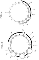
- the upper level 4 of the carousel 2 from FIG. 1 is shown schematically with sixteen holding devices 5, which are labeled with the positions 1 'to 16', to explain the process of forming a vial.
- the new forming station can interact with a vial machine with any number of chucks 7.
- the holding chucks 7 are opened and, as described above, the respective glass tube 12 is dropped onto a height-adjustable baffle plate and then gripped by the lower holding device 14.
- the glass tube section 34 is heated from positions 2 to 5 by means of burner Br to such an extent that it can be separated from the glass tube 12 in position 5 'by pulling the lower receiving device 14 downward.
- the new glass tube end 38 which closes in the process is opened again by means of the puncture burner 57 and the mouth region is heated to the forming temperature up to position 10 'by means of further burners Br.
- the first molding station with the molding roller 36a is arranged between the positions 10 'and 11', further molding stations are connected with molding rollers 36b and 36c between the positions 12 'and 13' or 14 'and 15'.
- Each forming station forms at a possibly different height at the glass tube end 38, so that with the described vial machine, mouth areas shaped over a larger longitudinal extent, e.g. for ampoules.
- Each form roller 36 can roll the glass tube end 38 as far as desired, the resulting inner diameter of the fully rolled glass tube end 38c (FIG. 5) being limited only by the diameter of the form finger.
- FIG. 4 is to be considered together with FIG. 1, in which the sixteen positions 1 'to 16' of the lower holding devices 14 of the carousel 2 from FIG. 1 are shown.
- the lower holding devices 14 work together with the respective upper holding devices 5 as described and separate a bottle preform in position 5 'from the glass tube 12.
- the bottom of the vial preform that closes in the process is further heated in a burner row Br arranged on the lower level 13 of the carousel 2 to the forming temperature up to the position 10 ′.
- the lower holding device 14 moves upwards and presses the heat-softened bottom of the vial preform against the bottom former 53.
- the bottom 61 is shaped up to position 11' and the finished vial 56 is lowered again in the lower holding device 14, so that the forming finger 43 in action in the upper level 4 can be pulled out of the corresponding glass tube end 38 again.
- a second cooling section K follows up to position 13, in which the finished vial 56 is cooled below the transformation temperature of the glass so that it no longer deforms when it is discharged from the carousel.
- the lower holding chuck 15 is opened in position 13, and as described above, the vial is removed using a gripper.
- the vial machine is not limited to the number of sixteen positions shown; eight to thirty-two positions are advantageous, and in special cases three to sixty-four positions or more can also be carried out.
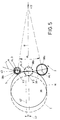
- FIG. 5 (which is to be considered together with FIG. 1) schematically shows a non-stop shaping by means of the shaping roller 36 over an angle ⁇ (angle between two adjacent receiving devices).
- the shaping roller 36 with its circumferential points X 1 and 3 closest to the chuck axes AL 1 and 3 of the corresponding holding chuck 7 is in contact with a fully formed mouth M of a fully rolled glass tube end 38c and a not yet shaped glass tube end 38a.
- the shaping roller 36 Since the carousel 2 rotates continuously in the direction of the arrow and pull the glass tube ends 38 in the holding chucks 7 along a circular run-out path L, the shaping roller 36 has to be pulled back from the carousel in a direction 42 essentially transversely to the run-way path L in a movement evading the glass tube end 38a will.
- the return movement of the form roller 36 takes place to a position I shown in dashed lines at such a speed that at the same time the rotating glass tube end 38a is rolled up by a certain amount.
- position I When position I is reached, the circumferential point closest to the chuck axis AL2 has X2 of the form roller 36, the glass tube end 38b has already been largely rolled up, and complete roll-up is already possible up to this position.
- the shaping roller 36 again moves in the direction of the axis of rotation KD of the carousel and, as it were, follows the glass tube end 38b continued in the carousel 2.
- the shaping roller 36 presses the heat-softened glass tube end 38 against a circular arc segment S of the shaping finger 43, which determines the inner radius of the mouth to be shaped.
- the circular arc segment S is designed such that it can support the heat-softened glass tube end 38 against the form roller 36 during the entire shaping.
- the glass tube end 38b is rolled up to the desired rolled diameter of the mouth M before reaching the position H, so that a certain smoothing time is still available until the position H is reached, in which the mouth area is no longer rolled, but until then Rolling in is stabilized.
- the shaping process begins anew at the subsequent glass tube end 38a.
- the rolled-up mouth region is preferably smoothed over 20% to 50% of the angle, in particular over 30% to 36%.
- a slide rail 42 ' which is offset by the distance Y, is also shown in dotted lines.
- the form roller is no longer displaced in the direction of a radial R of the carousel 2, but in the direction of a secant.
- the shaping roller 36 takes over the subsequent glass tube end 38a without gaps. If there are large differences between the outer diameters between the glass tube end 38a and the mouth M, however, it can make sense to work with a short break, since all the glass tubes 12 are driven at the same speed and accordingly have different path speeds due to the different outer diameters. In a short break, e.g. the speed of the form roller 36 can be increased somewhat, but in principle a short pause in the range of a few milliseconds prevents coupling of the different peripheral speeds of the glass tube end 38a or the mouth M via the form roller 36.
Abstract
Description
Die Erfindung betrifft eine Vorrichtung zum Verformen des Endbereiches eines Glasrohres zur Ausbildung eines Mündungsbereiches eines Fläschchens nach dem Oberbegriff des Anspruches 1, ein Verfahren zum Formen eines Fläschchens und die Verwendung der Vorrichtung in einer Fläschchenmaschine.The invention relates to a device for deforming the end region of a glass tube to form a mouth region of a vial according to the preamble of
Vorrichtungen zur Herstellung von Hohlkörpern wie Fläschchen, Ampullen etc. aus Glasrohr sind vielfach bekannt. Da diese Artikel in Massenfertigung hergestellt werden, soll eine preiswerte und schnelle Fertigung gewährleistet sein.Devices for the production of hollow bodies such as vials, ampoules, etc. from glass tubes are widely known. Since these articles are mass-produced, inexpensive and fast production should be guaranteed.
Die DE-PS 12 61 638 beschreibt eine bekannte Vorrichtung dieser Art, bei der ein Kranz von Aufnahmevorrichtungen Werkstücke in Form von Glasrohren in einer Werkstückbahn an mindestens einer Bearbeitungsstation vorbeidreht. Die Bearbeitungsstation enthält schwenkbare Auslegerarme, die Formgebungsteile tragen. Die Formgebungsteile werden in die Werkstückbahn hineingeschwenkt und können die Werkstücke auf einem Teilstück der Werkstückbahn formen, wobei das Teilstück durch die Größe und Anordnung der Auslegerarme stark beschränkt ist. Um die für einen Formgebungsvorgang nötige Zeit zur Verfügung zu haben, muß der Kranz mit den Werkstücken entweder während der Formung angehalten werden, oder darf sich nur sehr langsam drehen, oder der Formgebungsvorgang wird in mehrere Einzelformgebungsvorgänge unterteilt, wodurch wiederum eine Vielzahl von Bearbeitungsstationen für die Bearbeitung der gleichen Stelle am Fläschchen notwendig wird. Der Auslegerarm muß bei dieser Vorrichtung nach der Formung schnell in die Ausgangsposition zurückgeschwenkt werden, um mehr Zeit für die Formung zur Verfügung zu haben. Dies führt zu erhöhter mechanischer Beanspruchung und entsprechend zu erhöhtem Verschleiß.DE-PS 12 61 638 describes a known device of this type, in which a ring of holding devices rotates workpieces in the form of glass tubes in a workpiece path past at least one processing station. The processing station contains swiveling cantilever arms, which carry shaping parts. The shaping parts are pivoted into the workpiece path and can form the workpieces on a section of the workpiece path, the section being severely limited by the size and arrangement of the cantilever arms. In order to have the time required for a shaping process, the ring with the workpieces must either be stopped during the shaping, or may only rotate very slowly, or the shaping process is divided into several individual shaping processes, which in turn creates a multiplicity of processing stations for the Machining the same place on the vial becomes necessary. With this device, the cantilever arm must be swiveled back quickly into the starting position after the shaping in order to have more time available for the shaping. This leads to increased mechanical stress and correspondingly increased wear.
Um das Teilstück, auf dem die Formgebung erfolgt, zu vergrößern, hat man in einer aus der DE-PS 15 96 410 bekannten Vorrichtung die Formgebungsrollen auf eine Transportvorrichtung gesetzt, die für die Dauer der Formung mit der Winkelgeschwindigkeit des Kranzes mit den Werkstücken und parallel zu den Werkstücken mitfährt, so daß das zu formende Werkstück bzgl. der Transportvorrichtung stationär ist. Um während der Rückführung der Transportvorrichtung das nachfolgende Werkstück zu formen, müssen mehrere Transportvorrichtungen mit Formgebungsrollen eingesetzt werden, wobei die Transportvorrichtung z.B. über eine Kette miteinander verbunden sein können, so daß, während die erste Transportvorrichtung zurückfährt, eine weitere Transportvorrichtung zur Formgebung neben dem nachfolgenden Werkstück herfährt. Jede Transportvorrichtung hat hierdurch eine Bearbeitungspause von mindestens 100% der Formungszeit eines Fläschchens. Durch Toleranzen der einzelnen Transportvorrichtungen und der Formgebungsrollen entstehen entsprechend der Zahl von Transportvorrichtungen bei dieser Vorrichtung etwas voneinander abweichende Fläschchentypen.In order to enlarge the section on which the shaping takes place, the shaping rollers have been placed in a device known from DE-PS 15 96 410 on a transport device, which for the duration of the shaping with the angular speed of the ring with the workpieces and parallel travels to the workpieces so that the workpiece to be shaped is stationary with respect to the transport device. In order to form the subsequent workpiece during the return of the transport device, several transport devices with shaping rollers must be used, the transport device e.g. can be connected to one another via a chain, so that while the first transport device moves back, another transport device for shaping moves alongside the subsequent workpiece. As a result, each transport device has a processing break of at least 100% of the forming time of a vial. Tolerances of the individual transport devices and the shaping rollers result in slightly different vial types in this device, depending on the number of transport devices.
Der Erfindung liegt die Aufgabe zugrunde, eine Vorrichtung zur Herstellung von Hohlkörpern aus Glasrohren zu schaffen, wobei keine oder nur kurze Bearbeitungspausen auftreten sollen und eine hohe Herstellungsgeschwindigkeit möglich sein soll. Dabei soll der mechanische Aufwand für die Bearbeitungsstation möglichst gering sein, um geringe Toleranzen bei den gefertigten Fläschchen zu erhalten. Außerdem soll, unter Verwendung der Vorrichtung, eine Fläschchenmaschine Glasrohre mit verschiedenen Wandstärken oder Außendurchmessern verarbeiten können, ohne daß dadurch langwierige Umbauarbeiten oder Einstellungsarbeiten notwendig werden. Aufgabe der Erfindung ist auch ein Verfahren zur Herstellung eines Fläschchens.The invention has for its object to provide a device for the production of hollow bodies from glass tubes, wherein no or only short processing breaks should occur and a high production speed should be possible. The mechanical effort for the processing station should be as low as possible in order to obtain low tolerances in the vials produced. In addition, using the Device, a vial machine can process glass tubes with different wall thicknesses or outside diameters without the need for lengthy conversion work or adjustment work. The object of the invention is also a method for producing a vial.
Diese Aufgabe wird bei einer gattungsgemäßen Vorrichtung gemäß dem kennzeichnenden Teil des Anspruches 1 gelöst.This object is achieved in a generic device according to the characterizing part of
Im Gegensatz zu dem Erfahrungsstand nach dem Stand der Technik ermöglicht die Erfindung eine Massenherstellung von einheitlichen Fläschchen ohne hohe mechanische Beanspruchung der Formgebungsteile. Fläschchen steht im folgenden für alle aus einem Rohr herstellbare Hohlkörper, wie z.B. Rollrandfläschchen, Schnappdeckelgläser, Ampullen etc. Es hat sich gezeigt, daß mittels der Formrolle, die relativ zu dem vorbeifahrenden Glasrohr vor- und zurückschiebbar ist und während der Formgebung einfach durch eine Vor- und Zurückbewegung dem Glasrohr unter Einrollung desselben ausweicht, die Leerlaufzeiten der Formgebungsteile minimiert und sogar völlig vermieden werden können, da sich die Formrolle gegen Ende des Einrollens in der Startposition für die Formgebung des nachfolgenden Glasrohres befindet. Dies ermöglich ein kontinuierliches Drehen des Karussells mit beträchtlicher Drehzahl und damit eine kontinuierliche Massenherstellung der Hohlkörper mit hoher Herstellungsgeschwindigkeit.In contrast to the level of experience according to the prior art, the invention enables mass production of uniform vials without high mechanical stress on the shaping parts. In the following, vial stands for all hollow bodies that can be produced from a tube, e.g. Rolled-edge vials, snap-lid jars, ampoules etc. It has been shown that by means of the form roller, which can be pushed back and forth relative to the passing glass tube and which simply evades the glass tube by rolling it back and forth during shaping, the idle times of the shaped parts can be minimized and even completely avoided since the form roller is in the start position for the shaping of the subsequent glass tube towards the end of the curling. This enables the carousel to be continuously rotated at a considerable speed and thus a continuous mass production of the hollow bodies at a high production speed.
Ein besonderer Vorteil der Erfindung besteht darin, daß die Vor- und Zurückbewegung der Formrolle mit geringem Aufwand mittels eines Feinantriebes und einer programmierbaren Steuereinrichtung gesteuert werden kann, so daß sich die Formgebungsparameter leicht verändern und anderen Bedingungen, wie z.B. anderen Glasrohrdurchmessern, anpassen lassen. Das Verschieben der Formrolle erfolgt auf einer Geraden, so daß der mechanische Aufwand besonders gering ist.A particular advantage of the invention is that the back and forth movement of the form roller is controlled with little effort by means of a fine drive and a programmable control device can be changed so that the shaping parameters can be easily changed and adapted to other conditions, such as other glass tube diameters. The form roller is moved on a straight line, so that the mechanical outlay is particularly low.
Mit der Vorrichtung können Hohlkörper wie z.B. Fläschchen, Ampullen, Kerzenlampen etc. aus Glasrohren geformt werden, die in rotierbaren Haltefuttern auf einer Ablaufbahn, insbesondere in einem Karussell, an der erfindungsgemäßen Vorrichtung vorbeifahrbar sind.Hollow bodies such as e.g. Vials, ampoules, candle lamps, etc. are formed from glass tubes, which can be passed by the device according to the invention in rotatable holding chucks on a runway, in particular in a carousel.
Vorzugsweise ist die Achse der Formrolle zu der Glasrohrachse im wesentlichen parallel, so daß während der Formgebung die Formrolle immer in gleicher Höhe an dem zu verformenden Teil des Glasrohres ansetzt. Sollte jedoch eine Verschiebung der Glasmasse während der Formgebung erwünscht sein, so kann die Formrolle auch leicht schräg gegen das Glasrohr angesetzt werden.Preferably, the axis of the form roller is substantially parallel to the glass tube axis, so that the shape roller always attaches to the part of the glass tube to be deformed at the same height during shaping. However, if a shift in the glass mass is desired during shaping, the shaping roller can also be placed slightly obliquely against the glass tube.
Die Formrolleneinrichtung ist vorteilhafterweise in bezug auf die Ablaufbahn der Haltefutter stationär angeordnet und dabei in eine Richtung im wesentlichen quer zur Richtung der Ablaufbahn der Haltefutter beweglich, wobei vorzugsweise eine Phasenverschiebung zwischen der periodischen Hin- und Herbewegung der Formrolle und der periodischen Folge der vorbeibewegten Haltefutter eingestellt wird. Hierdurch ist die Änderung des Abstandes des einer Futterachse nächsten Punktes des Formrollenumfanges von dieser Futterachse während der relativen Bogenbewegung der Formrolle um die Futterachse möglich bei gleichzeitiger bis zu 100%iger Ausnutzung der Dauer einer periodischen Folge als Formzeit.The form roller device is advantageously arranged stationary in relation to the run-out path of the holding chuck and is movable in a direction essentially transverse to the direction of the run-off path of the holding chuck, a phase shift preferably being set between the periodic reciprocating movement of the form roll and the periodic sequence of the holding chuck moving past becomes. This makes it possible to change the distance of the point of the form roller circumference closest to a chuck axis from this chuck axis during the relative arc movement of the form roller around the chuck axis with simultaneous use of up to 100% of the duration of a periodic sequence as the form time.
Auch ein schräges Anstellen der Hin- und Herbewegung der Formrolleneinrichtung zur Richtung der Ablaufbahn der Haltefutter hin ist möglich, wobei dann unter einem bestimmten Winkel, der insbesondere von dem Formgebungsgrad und dem Durchmesser der Glasrohre abhängig ist, keine Phasenverschiebung zwischen der periodischen Hin- und Herbewegung der Formrolle und der periodischen Folge der vorbeibewegten Haltefutter notwendig ist. Die schräge Anstellung ist besonders bei einer kreisförmigen Ablaufbahn der Haltefutter vorteilhaft, wobei dann die schräge Anstellung einfach durch eine horizontale Versetzung der Gleitschiene der Formrolle aus einer Radialen der Kreisbahn in Richtung der Ablaufbahn erreicht werden kann. Das Maß der Versetzung bestimmt sich dabei aus den Abmessungen der Fläschchenmaschine und der Fläschchen, wie den Radien des Karussells, des Glasrohres, der Formrolle, der geformten Mündung sowie dem Drehwinkel des Karussells, über den die Formung erfolgt. Vorzugsweise weicht die schräge Anstellung nur wenige Grade von der senkrechten (quer) Anstellung ab, wobei sich Anstellwinkel von 80° - 90°, vorteilhafterweise 85° - 90°, als günstig für den Formprozeß ergeben haben. Der geeignetste Anstellwinkel ist, wie oben beschrieben, 90°.It is also possible to incline the to-and-fro movement of the form roller device in the direction of the run-out path of the holding chuck, with no phase shift between the periodic to-and-fro movement at a certain angle, which is dependent in particular on the degree of shaping and the diameter of the glass tubes the form roller and the periodic sequence of the passing chuck is necessary. The inclined position is particularly advantageous in the case of a circular running path of the holding chuck, in which case the inclined position can be achieved simply by horizontally displacing the slide rail of the form roller from a radial of the circular path in the direction of the running path. The degree of displacement is determined from the dimensions of the vial machine and the vials, such as the radii of the carousel, the glass tube, the form roller, the shaped mouth and the angle of rotation of the carousel, through which the shaping takes place. Preferably, the inclined angle deviates only a few degrees from the vertical (transverse) angle, angles of attack of 80 ° -90 °, advantageously 85 ° -90 °, having proven to be favorable for the molding process. The most suitable angle of attack, as described above, is 90 °.
Vorteilhafterweise sind die Haltefutter an einem mit stetiger Drehbewegung antreibbaren Drehtisch angeordnet, so daß diese eine Kreisbahn beschreiben, wobei die Rohrachsen vorzugsweise parallel und im gleichen Teilungsabstand zueinander auf einem Zylindermantel liegen. Bei dieser Anordnung sind die einzelnen Arbeitschritte, wie Einbringen der Glasrohre in die Maschine, die einzelnen Bearbeitungsschritte sowie die weitere Bearbeitung des Fläschchens nach der Formung der Mündung in einer einzigen, kompakten Fläschchenmaschine möglich.The holding chucks are advantageously arranged on a turntable which can be driven with a constant rotary movement, so that they describe a circular path, the tube axes preferably being parallel and at the same spacing from one another on a cylinder jacket. With this arrangement, the individual steps, such as inserting the glass tubes into the machine, are the individual ones Processing steps and further processing of the vial after the mouth is formed in a single, compact vial machine.
Vorzugsweise hat die Formrolleneinrichtung nur eine einzige Formrolle, deren Rand vorteilhafterweise ein die Außenseite des Mündungsabschnittes formendes Profil aufweist. Ein solches Profil ist auch mit z.B. zwei übereinander liegenden Formrollen möglich, die bzgl. der Drehachse des Glasrohres in unterschiedlichen Abständen auf dem Glasrohr abrollen.The shaping roller device preferably has only a single shaping roller, the edge of which advantageously has a profile that forms the outside of the mouth section. Such a profile is also with e.g. two form rollers lying one above the other are possible, which roll on the glass tube at different distances with respect to the axis of rotation of the glass tube.
Vorteilhafterweise wird die Formrolle im Inneren des Glasrohrendes von einem solchen Formfinger unterstützt, der einen kleineren Querschnitt als der angestrebte Innenquerschnitt des zu formenden Glasrohrendes aufweist und mit einem Kreisbogensegment versehen ist, welches sich vorteilhaft über mindestens denjenigen Umfangswinkel erstreckt, über den die Formrolle im Eingriff mit dem Glasrohr abrollt, wobei der Radius des Kreisbogensegmentes günstigerweise gleich dem Radius des angestrebten Innenquerschnittes ist. Ein solcher Formfinger ist nicht über seinen gesamten Umfang in Kontakt mit dem wärmeerweichten Glas und kann somit einfacher aus der fertig geformten Mündung wieder herausgeführt werden.The form roller in the interior of the glass tube end is advantageously supported by such a form finger, which has a smaller cross section than the desired inner cross section of the glass tube end to be shaped and is provided with a circular arc segment, which advantageously extends over at least the circumferential angle over which the form roller engages with rolls off the glass tube, the radius of the circular arc segment advantageously being equal to the radius of the desired inner cross section. Such a form finger is not in contact with the heat-softened glass over its entire circumference and can therefore be more easily removed from the finished mouth.
Zur Vermeidung einer Leerlaufzeit während des Wechsels der Formrolle zwischen zwei aufeinanderfolgenden Haltefuttern wird der Durchmesser der Formrolle so gewählt, daß er größer ist als der Teilungsabstand zwischen den Haltefuttern, vermindert um den minimal verarbeitbaren Glasrohrradius plus vermindert um den minimalen Mündungsradius. Hierdurch ist bei allen verwendbaren Glasrohr- und Mündungsdurchmessern immer eine pausenlose Formung möglich. Vorteilhafterweise wird ein Durchmesser der Formrolle gewählt, der 30% bis 100% größer ist als der Teilungsabstand zwischen den Haltefuttern, vermindert um den minimal verarbeitbaren Glasrohrradius und vermindert um den minimalen Mündungsradius, wodurch sich eine günstige Charakteristik der Hin- und Herbewegung der Formrolle bei praktisch allen verwendbaren Glasrohrdurchmessern ergibt.To avoid idle time when changing the form roller between two successive chucks, the diameter of the form roller is chosen so that it is greater than the pitch between the chucks, reduced by the minimum processable glass tube radius plus reduced by the minimum Muzzle radius. As a result, non-stop shaping is always possible with all usable glass tube and mouth diameters. Advantageously, a diameter of the form roller is chosen which is 30% to 100% larger than the pitch between the holding chucks, reduced by the minimally processable glass tube radius and reduced by the minimum mouth radius, which has a favorable characteristic of the back and forth movement of the form roller with practical results in all usable glass tube diameters.
Die Formrolle auf dem stationären Support läßt sich präzise auf einem Schlitten hin- und herbewegen, welcher mit einem Servomotor über eine Leitachsbahnsteuerung synchron zur periodischen Folge der vorbeibewegten Haltefutter verschiebbar ist. Diese Anordnung hat sich bei der gebotenen Präzision der beschriebenen Formgebung als besonders günstig erwiesen.The form roller on the stationary support can be moved back and forth precisely on a slide, which can be moved with a servo motor via a guide axis control system in synchronism with the periodic sequence of the holding chucks moved past. This arrangement has proven to be particularly favorable given the precision of the shape described.
Vorteilhaft ist auch eine Anfederung der Formrolle, z.B. auf dem Schlitten oder des gesamten Schlittens, so daß die Formrolle relativ zur theoretischen Bewegung elastisch gegen das zu verformende Glasrohrende wirkt. Durch diese Maßnahme wird eine Zerstörung oder übermäßige Belastung von mechanischen Teilen vermieden, wenn z.B. ein harter, nicht verformbarer Gegenstand, wie z.B. ein Glassplitter, die Formgebung der Formrolle stört. Je nach Härte eines solchen störenden Gegenstandes könnte die Genauigkeit der erfindungsgemäßen Vorrichtung durch Zerstörung oder Beschädigung bestimmter mechanischer Komponenten, wie z.B. der Aufhängung der Formrolle oder des Formfingers, nachlassen, die Anfederung dient hier als Sicherheitselement.Springing of the form roller, for example on the slide or the entire slide, is also advantageous, so that the shape roller acts elastically relative to the theoretical movement against the glass tube end to be deformed. This measure prevents destruction or excessive loading of mechanical parts if, for example, a hard, non-deformable object, such as a piece of glass, interferes with the shaping of the form roller. Depending on the hardness of such a disruptive object, the accuracy of the device according to the invention could deteriorate due to the destruction or damage of certain mechanical components, such as, for example, the suspension of the form roller or the form finger. The springing serves as a safety element here.
Die Anfederung ermöglicht außerdem auch die Verarbeitung von unterschiedlichen Glasmassen (bedingt durch unterschiedliche Glasrohrqualitäten) im Mündungsbereich, wodurch eine z.B. vergrößerte Glasmasse gleichmäßig über den Mündungsbereich so verteilt wird, daß ein etwas größerer, aber dennoch kreisrunder Außendurchmesser entsteht. Um dies zu erreichen, wird zweckmäßigerweise der Mündungsbereich unter Anfederung geformt, wobei die Feder während der Formgebung nicht an einem Anschlag ist.The springing also enables the processing of different glass masses (due to different glass tube qualities) in the mouth area, which means e.g. enlarged glass mass is evenly distributed over the mouth area so that a slightly larger, but circular outer diameter is created. In order to achieve this, the mouth region is expediently shaped with spring action, the spring not being in contact with a stop during the shaping.
Bei dem Verfahren zum Formen eines Fläschchens aus einem Glasrohr, bei dem aus dem einem Ende des Glasrohres das Fläschchen geformt wird und das die Schritte
Transportieren eine Anzahl von Glasrohren in gleichen Teilungsabständen kontinuierlich entlang einer Ablaufbahn,
Erwärmen des eines Endes jedes Glasrohres,
Formen einer Mündung durch Einrollen des wärmeerweichten Glasrohrendes mit einer Formrolle gegen einen Formstachel, wobei das Glasrohr um seine Längsachse rotiert,
Abtrennen des Glasrohrabschnittes mit der geformten Mündung vom Glasrohr, und
Formen eines Fläschchenbodens in den abgetrennten Glasrohrabschnitt
aufweist, wird die Aufgabe dadurch gelöst, daß die Formrolle relativ zu der Ablaufbahn hin und herbewegt wird mit der Periodizität der vorbeibewegten Glasrohre, daß die Formrolle unter Verkleinerung des Abstandes ihres einer vorbeibewegten Glasrohrlängsachse nächstliegenden Umfangpunktes zu dieser Längsachse relativ zu dieser bogenförmig um diese herum bewegt wird, und daß die Formrolle dabei bei Annäherung eines Glasrohres von der Ablaufbahn der Glasrohre zurückbewegt wird und bei sich entfernenden Glasrohr wieder gegen die Ablaufbahn in den Abstandraum zwischem dem sich entfernenden und den nachfolgenden Glasrohr vorbewegt wird.In the method of forming a vial from a glass tube, in which the vial is formed from one end of the glass tube and the steps
Transport a number of glass tubes at equal intervals continuously along a runway,
Heating one end of each glass tube,
Forming a mouth by rolling in the heat-soaked glass tube end with a molding roller against a molding spike, the glass tube rotating about its longitudinal axis,
Separating the glass tube section with the shaped mouth from the glass tube, and
Form a vial bottom into the severed glass tube section
has, the object is achieved in that the form roller relative to the runway back and forth is moved with the periodicity of the glass tubes moving past, that the form roller is moved in an arc around this longitudinal axis relative to this longitudinal axis relative to this longitudinal axis relative to the longitudinal axis, which is closest to a longitudinal axis of a glass tube moving past, and that the form roller moves back from the run-off path of the glass tubes when a glass tube approaches and when the glass tube is removed, it is again moved against the run-off path into the space between the glass tube which is being removed and the subsequent one.
Im folgenden werden die Erfindung und die damit erzielbaren Vorteile anhand eines Ausführungsbeispiels, einer Maschine zur kontinuierlichen Herstellung von Fläschchen aus Glas (Fläschchenmaschine) in Verbindung mit den Zeichnungen näher beschrieben.
Figur 1- zeigt einen Schnitt durch die Fläschchenmaschine entlang der Karussellachse;
Figur 2- zeigt eine Formrolleneinrichtung in einer vergrößerten Darstellung;
Figur 3- zeigt schematisch einzelne Formgebungsschritte in einer oberen Ebene des Karussells;
- Figur 4
- zeigt schematisch einzelne Formgebungsschritte in einer unteren Ebene des Karussells; und
Figur 5- zeigt schematisch die Bewegung der Formrolle in Draufsicht.
- Figure 1
- shows a section through the vial machine along the carousel axis;
- Figure 2
- shows a form roller device in an enlarged view;
- Figure 3
- shows schematically individual shaping steps in an upper level of the carousel;
- Figure 4
- shows schematically individual shaping steps in a lower level of the carousel; and
- Figure 5
- shows schematically the movement of the form roller in plan view.
Bei der Formung eines Fläschchens aus einem Glasrohr werden alle Bearbeitungsschritte in einer Fläschchenmaschine 1 durchgeführt, die eine obere Ebene 4 und eine untere Ebene 13 aufweist. Die Ebenen 4 und 13 sind fest miteinander verbunden und bilden ein zweistöckiges Karussell 2, das über Lager 80 auf einem Gestell 3 gelagert ist. Am Umfang der oberen Ebene 4 sind in regelmäßigen Teilungsabständen um ihre eigenen Längsachsen drehbare erste Aufnahmevorrichtungen 5 befestigt, deren untere Enden je ein mittels eines pneumatischen Zylinders 6 öffen- und schließbares Haltefutter 7 aufweisen. In dem dargestellten bevorzugten Ausführungsbeispiel hat die Ebene 4 einen Durchmesser von ca. 80 cm (gemessen von den Längsachsen AL zweier einander gegenüberliegender Aufnahmevorrichtungen 5) und trägt 16 Aufnahmevorrichtungen 5. Der Durchmesser der Ebene 4 liegt bevorzugt bei 60 cm bis 120 cm, wobei der Abstand zweier benachbarter Aufnahmevorrichtungen 5 günstigerweise von 11 cm bis 23 cm beträgt.When a vial is formed from a glass tube, all processing steps are carried out in a
Zum Öffnen des Haltefutters 7 zieht der pneumatische Zylinder 6 eine Gabel 8 mit zwei Rollen 8a, die in einer umlaufenden Nut 81 einer Schiebehülse 9 laufen, gegen eine Feder 10, wodurch die Schiebehülse 9 Spannbacken 11 zurückzieht und ein Glasrohr 12 freigibt. Statt pneumatischer sind auch z.B. elektromagnetische und rein mechanische, über Kurven gesteuerte Federkraftsteuerungen möglich. Maßgebend ist, daß die Haltefutter weich schließen, um das Glasrohr nicht zu zerstören. Prinzipiell sind auch andere Arten geeigneter Futter zum Halten der Rohre geeignet.To open the holding
Zur Verarbeitung in der Fläschchenmaschine 1 sind Glasrohre 12 mit einem Außendurchmesser von 13 mm bis 50 mm und mit einer Wandstärke von 0,5 mm bis 3,0 mm besonders geeignet.
Die Längsachsen AL der ersten Aufnahmevorrichtungen 5 verlaufen bei der dargestellten Ausführungsform zur Vereinfachung des Aufbaues parallel zur Karusselldrehachse KD. Unterhalb jeder ersten Aufnahmevorrichtung 5 ist in der unteren Ebene 13 des Karussells 2 jeweils eine um ihre eigene Längsachse drehbare zweite Aufnahmevorrichtung 14 mit ebenfalls einem Haltefutter 15 so angeordnet, daß gegenüberliegende erste und zweite Aufnahmevorrichtungen bzw. deren Haltefutter jeweils eine gemeinsame Längsachse aufweisen. Die Haltefutter 15 der zweiten Aufnahmevorrichtungen 14 sind über eine (nicht dargestellte) Kurve steuerbar, die von oben auf einen Zylinder 16 und über eine Gabel mit zwei Rollen 86, die in einer Nut 85 einer Schiebehülse 83 geführt sind, wirkt und hierdurch, wie oben beschrieben, gegen einen Federdruck 82 Spannfutter 84 des Haltefutters 15 öffnet. Auch bei dem Haltefutter 15 ist eine pneumatische oder elektromagnetische Betätigung möglich, maßgebend ist auch hier, daß das Haltefutter weich schließt, um das von diesem Backenfutter gehaltene Glasrohrende bzw. Fläschchen nicht zu zerstören.The longitudinal axes AL of the
Ein steuerbarer Motor 17 mit Inkrementalgeber dreht das Karussell 2 mit den Aufnahmevorrichtungen 5 und 14 über ein Zahnradpaar 18. Zur Rotation der Aufnahmevorrichtungen 5 und 14 um ihre eigenen Drehachsen AL ist ein unabhängig von dem Motor 17 steuerbarer zweiter Motor 19 vorgesehen, der über ein Zahnradpaar 20 (oder einen nicht dargestellten Zahnriementrieb), ein Rohr 21 und ein Zahnradpaar 22 (oder direkt mit einer (nicht dargestellten) Kette über ein Kettenrad 22a) auf eine Welle 23 wirkt, die an ihrem oberen und unteren Ende Kettenräder 24 und 25 aufweist, über die die Aufnahmevorrichtungen 5 und 14 mit Kettenrädern 26 und 27 mittels nicht dargestellter Ketten gleichsinnig und mit gleichem Übersetzungsverhältnis angetrieben werden, so daß die oberen und unteren Aufnahmevorrichtungen 5 und 14 mit gleicher Drehzahl rotieren.A
Um ein Verschieben der zweiten Aufnahmevorrichtung 14 in Längsrichtung zu ermöglichen, sitzt diese in einer Vielkeilnabe 28, die den Drehantrieb des Kettenrades 27 kraftschlüssig auf die zweite Aufnahmevorrichtung 14 überträgt, aber gleichzeitig eine freie Verschiebung derselben in Längsrichtung ermöglicht. Zum Verschieben der zweiten Aufnahmevorrichtung 14 in Längsrichtung ist eine Hebevorrichtung 30 vorgesehen, die in einer Führungshülse 29 verschiebbar angeordnet ist und über ein Rad 31 über eine Kurve 32 geführt wird. Die Kurve 32 kann in ihrer Höhe veränderbar ausgeführt sein, so daß der Hub der zweiten Aufnahmevorrichtung 14 einer unterschiedlichen Arbeitshöhe für verschieden lange Fläschchen anpaßbar ist.In order to make it possible to move the
Außerhalb des Karussells 2 sind unterhalb der ersten Aufnahmevorrichtungen 5 mehrere Brenner 33 angeordnet, die einen drehend herbeigeführten, aus den ersten Aufnahmevorrichtungen 5 herausstehenden Glasrohrabschnitt 34 auf eine Temperatur erhitzen, bei der dieser durch Zug vom Glasrohr 12 abgetrennt werden kann. Ein sich dabei ggf. verschließendes Glasrohrende 38 wird mittels eines Stichbrenners 57 (Fig. 3) wieder geöffnet und durch weitere (nicht dargestellte) Brenner wieder erhitzt.Outside the
In Drehrichtung des Karussells 2 an diese Brenner anschließend folgt eine Formstation 35, die auf einer Basis 75 außerhalb des Karussells 2 angeordnet ist und zur Formung einer Mündung M in die Glasrohrenden 38 dient. Die Formstation 35 trägt eine Formrolle 36, die im wesentlichen die Form einer Scheibe hat und die an ihrem Umfang zur Formung der Mündung M in das Glasrohrende 38 ein Profil 37 aufweisen kann.In the direction of rotation of the
Die Formrolle 36 hat einen Durchmesser, der größer ist als der Abstand zwischen zwei aufeinanderfolgenden Glasrohren 12 und wird so geführt, daß sie möglichst ständig in Kontakt mit einem Glasrohrende 38 ist, d.h., daß die Formrolle 36 praktisch ständig von einem zwangsgedrehten Glasrohrende 38 angetrieben wird und daher keine Drehpause hat. Hierdurch treten nur geringe Reibungskräfte zwischen der Formrolle 36 und einem neu mit ihr in Kontakt kommenden Glasrohrende 38 durch unterschiedliche Bahngeschwindigkeiten der jeweiligen Umfänge auf, da die Formrolle 36 nur geringfügig von dem neuen Glasrohrende 38 beschleunigt werden muß. Zur Unterstützung der Rotation der Formrolle 36 kann die Formrolle 36 mit einem Propeller 58 versehen sein, über den die Formrolle 36 mittels eines Luftstroms angetrieben werden kann. Im dargestellten bevorzugten Ausführungsbeispiel hat die Formrolle 36 einen Durchmesser von ca. 20 cm, günstig sind allgemein Durchmesser von 15 cm bis 28 cm.The
An der Formstation 35 ist ein steuer- und regelbarer Feinantrieb 39 mit Inkrementalgeber befestigt, der über eine Gewindespindel 40 einen Schlitten 41, der auf einer Gleitschiene 42 sitzt, verschiebt. Auf dem Schlitten 41 ist die Formrolle 36 drehbar gelagert angeordnet und zur Formung der Mündung in einer geeigneten Höhe zum Glasrohrende 38 justiert.A controllable and adjustable fine drive 39 with an incremental encoder is fastened to the forming
Die rotierenden Glasrohre 12 werden durch Drehen des Karussells 2 an der Formstation 35 vorbeigefahren. Die Formrolle 36 paßt sich dabei mit einer geradlinigen Hin- und Herbewegung, die im wesentlichen radial zum Karussell 2 verläuft, der Kreisbahn des rotierenden Glasrohres 12 unter gleichzeitigem Einrollen des Glasrohrendes 38 an. Auch eine transversale (Sekante) Hin- und Herbewegung zum Karussell 2 ist möglich, dabei steht die Hin- und Herbewegung dann in einer anderen Phasenverschiebung zur periodischen Folge der vorbeifahrenden Haltefutter 7. Gegen Ende der Formgebung ist die Formrolle 36 vorzugsweise so weit zur Karusselldrehachse KD verschoben, daß der Freiraum bis zum nachfolgenden Glasrohrende 38 von der Formrolle 36 ganz ausgefüllt wird, so daß diese sofort mit der Formung des nachfolgenden Glasrohrendes 38 beginnen kann.The
Prinzipiell ist es ausreichend, wenn die Formstation 35 bzgl. des Karussells einmal so ausgerichtet wird, daß die Hin- und Herbewegung der Formrolle 36, wie oben beschrieben, radial zum Karussell 2 erfolgt. Die Formstation 35 kann dann fest mit dem Gestell 3 verbunden sein. Soll jedoch auch eine transversale Hin- und Herbewegung der Formrolle 36 bzgl. des Karussells 2 möglich sein, so wird unten an der Basis 75 eine Querführung 60 bzgl. des Karussells 2 vorgesehen, in der die gesamte Formstation 35 in einer Richtung quer zur Gleitschiene 42 verschiebbar ist. Diese Verschiebung kann mittels Hand z.B. über eine Handkurbel erfolgen, vorteilhafterweise geschieht dies jedoch mittels eines Schrittmotors 44, der über ein Zahnrad 45 auf eine Zahnstange 46 wirkt und dadurch die Formstation 35 in tangentialer Richtung zum Karussell 2 um einen definierten Betrag verschiebt. Wichtig ist hierbei, daß die Querführung 60 während des Formprozesses gegen ein unbeabsichtigtes Verschieben gesichert ist.In principle, it is sufficient if the
Alternativ kann diese transversale (Sekante) Hin- und Herbewegung zum Karussell 2 und die damit verbundene Phasenverschiebung zur periodischen Folge der vorbeifahrenden Haltefutter 7 auch durch die Software der Leitachsenbahnsteuerung realisiert werden.Alternatively, this transverse (secant) back and forth movement to the
Weitere entsprechende Formstationen mit weiteren Formrollen 36b, 36c (Fig. 3) können in Drehrichtung des Karussells 2 angebracht sein, wobei vorzugsweise bis zu drei Formstationen verwendet werden, die das Glasrohrende 38 vorteilhafterweise in unterschiedlichen Höhen einrollen, wodurch eine besondere Ausgestaltung des Halsbereiches eines Fläschchens oder einer Ampulle möglich ist.Further corresponding shaping stations with further shaping
Zur Unterstützung des Glasrohrendes 38 während der Formgebung ist ein Formfinger 43 vorgesehen, der positionsgenau unter die Mitte des Glasrohres 12 bringbar und in das Glasrohrende 38 einfahrbar ist. Der eingefahrene Formfinger 43 bildet für das von der Formrolle 36 eingedrückte, wärmeerweichte Glasrohrende 38 ein Widerlager, bis zu dem die Einrollung des Glasrohrendes 38 erfolgt. Durch den Abstand der der Formrolle 36 entgegengerichteten Wand des Formfingers 43 zur Längsachse des Glasrohres 12 wird entsprechend der Innendurchmesser der zu formenden Mündung am Glasrohrende 38 bestimmt. Vorzugsweise hat der Formfinger 43 einen Radius von 2 mm bis 50 mm.To support the
Bei den bisher bekannten Fläschchenmaschinen war bisher immer je ein Formfinger einer Werkzeug- oder Formstation zugeordnet, zusammen mit der neuen Formstation ist es jedoch günstiger, wenn jede Aufnahmevorrichtung 5 einen Formfinger 43 zugeordnet hat, wodurch mehr Zeit für das Ein- und Ausbringen des Formfingers 43 in das Glasrohrende 38 besteht und der Formfinger 38 auch genügend Zeit zum Abkühlen bis zum nächsten Formvorgang hat. Hierbei ist der Formfinger 43 in der Höhe verschiebbar an einem Horizontalschlitten 50 angebracht, der auf einer Schiene 52 über Rollen 51 vor- und zurückschiebbar ist. Die Schiene 52 ist auf einer mittleren Ebene 49 des Karussells 2 befestigt. Mittels des Horizontalschlittens 50 ist der Formfinger 43, der am vorderen Ende des Horizontalschlittens 50 sitzt, von einer Ruheposition A in die gemeinsame Längsachse der zugehörigen Aufnahmevorrichtungen 5 und 14 verschiebbar. In dieser Position B kann der Formfinger 43 mittels einer von einer Kurve 55 geführten Kurvenrolle 54 in das Glasrohrende 38 angehoben werden.In the previously known vial machines, one molding finger has always been assigned to a tool or molding station, but together with the new molding station, it is more advantageous if each receiving
Das Verschieben des Horizontalschlittens 50 erfolgt vorzugsweise mittels Druckluft über einen (nicht dargestellten) Pneumatikzylinder, der entweder direkt oder vorzugsweise wegen des geringen in radialer Ausdehnung zur Verfügung stehenden Raumes über eine (nicht dargestellte) Hebelanordnung mit dem Horizontalschlitten 50 verbunden sein kann.The
Um eine Überhitzung des Formfingers 43 zu vermeiden, wird dieser nach jeder Formgebung aus dem Glasrohrende 38 nach unten herausgezogen, auch wenn sich noch weitere Formstationen mit Formrollen 36b, 36c (Fig. 3) anschließen, da zwischen diesen Formrollen das Glasrohrende 38 mittels (nicht dargestellter) Brenner wieder erhitzt wird.In order to avoid overheating of the
Nach der letzten Formstation wird das fertig geformte Glasrohrende 38c (Fig. 5) unter die Transformationstemperatur des Glases abgekühlt und durch Öffnen des Haltefutters 7 auf eine entsprechend der Artikellänge in vertikaler Richtung verstellbare Prallplatte (nicht dargestellt) fallengelassen. Nachdem die Mündung auf der Prallplatte aufliegt, wird das Haltefutter 7 über Zylinder 6 wieder geschlossen. Anschließend wird die direkt unterhalb des Glasrohres 12 angeordnete zweite Aufnahmevorrichtung 14 über die Kurve 32 noch soweit nach oben gefahren, daß die fertig geformte Mündung M des Glasrohrendes 38 einen Stempel 47 gegen eine Feder 48 ein Stück weit in die zweite Aufnahmevorrichtung 14 hineinschiebt. Hierzu ist das untere Haltefutter 15 über den Zylinder 16 geöffnet und wird nach dem Hochfahren über denselben Zylinder wieder geschlossen, um das Glasrohr zu fassen.After the last shaping station, the fully formed
Der Glasrohrabschnitt 34 mit der fertig geformten Mündung M wird, wie oben beschrieben, mittels Brenner 33 so weit erhitzt, daß er durch Zug nach unten abtrennbar ist. Beim Abtrennen verschließt sich der abgetrennte Glasrohrabschnitt 34 an seinem oberen Ende unter Bildung einer Fläschchen-Preform. Das obere Glasrohr 12 wird, wie oben beschrieben, weiter verarbeitet und der abgetrennte Glasrohrabschnitt 34 fährt in der zweiten Aufnahmevorrichtung 14 weiter nach unten. Zur Formung eines Bodens 61 an die Fläschchen-Preform wird das obere Ende des abgetrennten Glasrohrabschnittes 34 mittels (nicht dargestellter) Brenner weiter erhitzt und die Fläschchen-Preform in einem Bodenformschritt zu einem fertigen Fläschchen 56 geformt. Die Formung des Bodens kann mittels einer außerhalb des Karussells angeordneten Bodenformstation erfolgen, wie sie z.B. die DE-PS 12 61 638 beschreiben. Wie in Figur 1 dargestellt, kann die Bodenformung aber auch besonders einfach an dem Horizontalschlitten 50 erfolgen.The
Hierzu ist an jedem Horizontalschlitten 50 unterhalb des Formfingers 43 je ein Bodenformer 53, der normalerweise ein Kohlepressling ist, angeordnet. Mit dieser Anordnung wird erreicht, daß der Bodenformer 53 mittels des Horizontalschlittens 50 zusammen mit dem Formfinger 43 in die gemeinsame Längsachse der Aufnahmevorrichtungen 5 und 14 fährt, wenn letzterer zur Mündungsformung in das untere Glasrohrende 38 eingebrach wird. In dieser Stellung des Bodenformers 53 fährt die zugehörige untere Aufnahmevorrichtung 14 über die Kurve 32 nach oben, bis der zu formende Boden 61 mit dem Bodenformer 53 in Kontakt kommt. Durch die oben beschriebene Drehung der zweiten Aufnahmevorrichtung 14 erfolgt eine gleichmäßige Bodenformung, wobei vor allem bei Glasrohren mit einer größeren Dicke (ab ca. 15 mm äußerer Durchmesser) vorteilhafterweise über die Aufnahmevorrichtung 14 eine Stützluft in das Fläschcheninnere gegen den Boden 61 eingeblasen wird, damit dieser nicht nach unten absackt, sondern mit der gesamten Bodenfläche in Kontakt mit dem Bodenformer 53 kommt.For this purpose, a bottom former 53, which is normally a carbon compact, is arranged on each
Nach der Bodenformung wird das fertig geformte Fläschchen 56 in der zweiten Aufnahmevorrichtung 14 über die Kurve 32 wieder abgesenkt, damit auch der Formfinger 43, wie oben beschrieben, aus dem unteren, nun geformten Glasrohrende 38c ausgefahren werden kann. Der Bodenformer 53 fährt dann mit dem Formfinger 43 mittels des Horizontalschlittens 50 in Richtung auf die Drehachse KD des Karussells 2 wieder in seine Ruheposition A zurück.After the bottom has been shaped, the finished-shaped
Danach wird das Fläschchen 56 abgekühlt, in einer nachfolgenden Station durch einen Entnahmegreifer im Bodenbereich gegriffen und anschließend durch Öffnen und Absenken der Spannbacken 84 des Haltefutters 15 freigegeben. Das leere Haltefutter 15 wird vorzugsweise automatisch von eventuellen Verunreinigungen gereinigt und anschließend zur Aufnahme des nächsten Glasrohrendes 38 nach oben gefahren, wobei der Formungsprozeß wieder von neuem beginnt.Thereafter, the
In Figur 2 ist der Aufbau einer Formstation 35 mit weiteren Einzelheiten dargestellt. Die Basis 75 der Formstation hat an ihrem Fuß die schon erwähnte Querführung 60 und die Zahnstange 46, mittels der die gesamte Formstation 35 in einer Richtung quer zur Arbeitsbewegung der Formrolle 36 versetzbar ist. Über die Querführung 60 ist es möglich, die Arbeitsbewegung der Formrolle 36 genau radial auf die Drehachse des Karussells auszurichten oder, sofern gewünscht, parallel zur Radialen zu versetzen, so daß eine transversale Richtung resultiert. Eine solche transversale Richtung ist vorzugsweise in Drehrichtung des Karussells von der radialen versetzt. An der Basis 75 sind der Feinantrieb 39 und die Gleitschiene 42 befestigt, auf der der Schlitten 41 für die Formrolle 36 sitzt. Eine Gewindestange 62 ist zum Verschieben des Schlittens 41 vorgesehen. Die Gewindestange 62 ist an ihrem einen Ende in der Formstationbasis 75 drehbar gelagert und an ihrem anderen Ende direkt mit dem Feinantrieb 39 verbunden. Der Schlitten 41 weist eine Gewindedurchführung 63 auf, durch die die Gewindestange 62 hindurchgeführt ist. Durch Drehen der Gewindestange 62 mittels des Motors 39 kann der Schlitten 41 entsprechend vor- bzw. zurück entlang der Gleitschiene 42 verschoben werden. Vorzugsweise ist die Gleitschiene 42 entweder doppelt ausgeführt oder hat einen, vom kreisförmigen abweichenden Querschnitt, so daß eine stabile Führung des Schlittens 41 gegeben ist und die Gewindestange 62 von einer seitlichen Belastung durch den Schlitten 41 entlastet ist.In Figure 2, the structure of a
In dem Schlitten 41 ist aus Sicherheitsgründen eine Anfederung vorgesehen, die ein Zurückweichen der Formrolle 36 bei einem zu hohen Andruckwiderstand - z.B. einem nicht genügend wärmeerweichten Glasposten - ermöglicht. Die Anfederung erfolgt im wesentlichen mit einem Pneumatikzylinder 68, der ein Trägerteil 69 in Richtung auf das Karussell 2 verschiebt. Das Trägerteil 69 wird dabei in einer Führung 70 in dem Schlitten 41 gehalten, wobei ein Anschlag 71 vorgesehen ist, damit das Trägerteil 69 durch den Zylinder 68 nicht aus dem Schlitten 41 herausgeschoben wird, wenn kein Widerstand gegen die Formrolle 36 wirkt. Bei einem zu großen Andruckwiderstand gegen die Formrolle 36 kann diese mit dem Trägerteil 69 gegen den Zylinder 68 in einen Ausweichraum 72 zurückweichen, so daß eine Beschädigung der Präzisionsteile vermieden wird. Ein weiterer positiver Effekt der Anfederung ist, daß sich die Formrolle 36 schwankenden Glasmengen während der Formung des Mündungsbereiches anpassen kann und damit auch bei etwas schwankenden Glasdicken des Glasrohres 12 die Formung eines kreisrunden Außendurchmessers im Mündungsbereich ermöglicht. Ohne diese Anfederung müßten Glasübermengen während der Formung zwischen dem Formfinger 43 und der Formrolle 36 durch diese nach oben bzw. unten weggeschoben werden, damit auch hier ein kreisrunder Außendurchmesser erreicht wird.For safety reasons, a spring is provided in the
In dem Trägerteil 69 des Schlittens 41 ist eine Welle 65 angebracht, auf der die Formrolle 36 über ein Lager 64 drehbar befestigt ist. Die Achse der Welle 65 ist vorteilhafterweise parallel zu den Glasrohrachsen angeordnet. Die Formrolle 36 weist an ihrem Rand das Profil 37 auf, dessen untere Ausnehmung 66 an der Mündung M einen Kragen 67 formt.In the carrier part 69 of the
Die Formrolle 36 ist auf der Welle 65 zusammen mit dem Lager 64 in der Höhe justierbar bzw. gegen eine anders ausgebildete Formrollen austauschbar. Dies ist erforderlich, um die Formrollen in ihrer Höhe bzgl. des Glasrohrendes 38 zu justieren und um anders gestaltete Mündungsbereiche zu formen.The height of the
Vorteilhafterweise weist die Formrolle 36 in ihrem Körper eine Vielzahl von Durchbrüchen 76 auf, die das Gewicht der Formrolle reduzieren, aber dennoch eine genügende Stabilität der Formrolle 36 gewähren. Hierdurch wird bei unterschiedlichen Umfangsgeschwindigkeiten zwischen der Formrolle 36 und dem zu formenden Glasrohrende 38 die Trägheit vermindert.Advantageously, the
In Figur 3 ist zur Erläuterung des Ablaufs einer Fläschchenformung schematisch die obere Ebene 4 des Karussells 2 aus Fig. 1 mit sechzehn Aufnahmevorrichtungen 5 dargestellt, die mit den Positionen 1' bis 16' bezeichnet sind. Prinzipiell kann die neue Formstation mit einer Fläschchenmaschine mit beliebiger Zahl von Haltefuttern 7 zusammenwirken.In FIG. 3, the upper level 4 of the
So sind für Spezialanwendungen z.B. 3 bis 64 Haltefutterpositionen denkbar, wobei 12 bis 24 Haltefutterpositionen besonders günstig sind.For example, for
In der Position 1' sind die Haltefutter 7 geöffnet und das jeweilige Glasrohr 12 wird, wie oben beschrieben, auf eine in der Höhe verstellbare Prallplatte fallengelassen und anschließend von der unteren Aufnahmevorrichtung 14 gegriffen. Gleichzeitig wird der Glasrohrabschnitt 34 von den Positionen 2 bis 5 mittels Brenner Br so weit erhitzt, daß es in der Position 5' durch Zug der unteren Aufnahmevorrichtung 14 nach unten vom Glasrohr 12 abgetrennt werden kann. Das sich dabei verschließende neue Glasrohrende 38 wird mittels des Stichbrenners 57 wieder geöffnet und der Mündungsbereich bis zur Position 10' mittels weiterer Brenner Br auf Formungstemperatur erhitzt. Zwischen den Positionen 10' und 11' ist die erste Formstation mit der Formrolle 36a angeordnet, weitere Formstationen schließen sich mit Formrollen 36b und 36c zwischen den Positionen 12' und 13' bzw. 14' und 15' an. Jede Formstation formt in einer möglicherweise unterschiedlichen Höhe am Glasrohrende 38, so daß mit der beschriebenen Fläschchenmaschine auch über eine größere Längsausdehnung geformte Mündungsbereiche, wie z.B. bei Ampullen, gefertigt werden können. Jede Formrolle 36 kann das Glasrohrende 38 beliebig weit einrollen, wobei dem resultierenden Innendurchmesser des fertig eingerollten Glasrohrendes 38c (Fig. 5) nur durch den Durchmesser des Formfingers Grenzen gesetzt sind.In position 1 ', the holding chucks 7 are opened and, as described above, the
Zwischen den Formrollen 36a bis 36c sind weitere Brenner Br angeordnet, die den zu formenden Mündungsabschnitt auf Formungstemperatur halten. Im Bereich der Positionen 15' und 16' wird der fertig geformte Mündungsbereich entlang einer ersten Kühlstrecke K abgekühlt, so daß dieser Bereich von dem unteren Haltefutter 15 ohne Deformierung des Glasmantels gegriffen werden kann (Position 1').Further burners Br are arranged between the shaping
Die Vollendung des Formprozesses wird in Figur 4, die zusammen mit Figur 1 zu betrachten ist, erläutert, in der die sechzehn Positionen 1' bis 16' der unteren Aufnahmevorrichtungen 14 des Karussells 2 aus Figur 1 dargestellt sind. In den Positionen 1' bis 5' arbeiten die unteren Aufnahmevorrichtungen 14 mit den jeweiligen oberen Aufnahmevorrichtungen 5 wie beschrieben zusammen und trennen dabei eine Fläschchen-Preform in Position 5' vom Glasrohr 12 ab. Der dabei sich verschließende Boden der Fläschchen-Preform wird in einer an der unteren Ebene 13 des Karussells 2 angeordneten Brennerreihe Br weiter auf Formungstemperatur bis zur Position 10' erhitzt. In Position 10' fährt die untere Aufnahmevorrichtung 14 nach oben und drückt den wärmeerweichten Boden der Fläschchen-Preform gegen den Bodenformer 53. Hierdurch wird bis zur Position 11' der Boden 61 geformt und das fertig geformte Fläschchen 56 in der unteren Aufnahmevorrichtung 14 wieder abgesenkt, damit auch der in der oberen Ebene 4 in Aktion befindliche Formfinger 43 wieder aus dem entsprechenden Glasrohrende 38 herausgezogen werden kann.The completion of the molding process is explained in FIG. 4, which is to be considered together with FIG. 1, in which the sixteen positions 1 'to 16' of the
Nach der Bodenformung BF schließt sich bis zur Position 13 eine zweite Kühlstrecke K an, in der das fertige Fläschchen 56 unter die Transformationstemperatur des Glases abgekühlt wird, damit es sich beim Austragen aus dem Karussell nicht mehr verformt. Zum Austragen des Fläschchens 56 wird in Position 13 das untere Haltefutter 15 geöffnet, und wie oben beschrieben das Fläschchen mittels ein Greifers entnommen.After bottom shaping BF, a second cooling section K follows up to position 13, in which the
In Position 15' und 16' wird das leere Haltefutter 15 automatisch von eventuellen Verunreinigungen zur Aufnahme des nächsten Mündungsbereiches gereinigt.In positions 15 'and 16', the empty holding
Die Fläschchenmaschine ist nicht auf die dargestellte Zahl von sechzehn Positionen beschränkt, vorteilhaft sind acht bis zweiunddreißig Positionen, in Spezialfällen sind auch drei bis vierundsechzig Positionen oder mehr ausführbar.The vial machine is not limited to the number of sixteen positions shown; eight to thirty-two positions are advantageous, and in special cases three to sixty-four positions or more can also be carried out.
In Figur 5 (die zusammen mit Fig. 1 zu betrachten ist) ist schematisch eine pausenlose Formung mittels der Formrolle 36 über einen Winkel α (Winkel zwischen zwei benachbarten Aufnahmevorrichtungen) dargestellt. In der durchgezogen gezeichneten Position H ist die Formrolle 36 mit ihren, den Futterachsen AL 1 und 3 der entsprechenden Haltefutter 7 nächstliegenden Umfangspunkten X 1 und 3 in Kontakt mit einer fertig geformten Mündung M eines fertig eingerollten Glasrohrendes 38c und einem noch nicht geformten Glasrohrende 38a. Da das Karussell 2 sich in Pfeilrichtung kontinuierlich dreht und die Glasrohrenden 38 in den Haltefuttern 7 entsprechend auf einer kreisförmigen Ablaufbahn L entlang ziehen, muß die Formrolle 36 vom Karussell in einer dem Glasrohrende 38a ausweichenden Bewegung in einer Richtung 42 im wesentlichen quer zur Ablaufbahn L zurückgezogen werden. Die Zurückfahrbewegung der Formrolle 36 erfolgt zu einer gestrichelt gezeichneten Position I mit einer solchen Geschwindigkeit, daß gleichzeitig das sich drehende Glasrohrende 38a um einen gewissen Betrag eingerollt wird. Beim Erreichen der Position I hat der, der Futterachse AL2 nächstliegende Umfangspunkt X2 der Formrolle 36 das Glasrohrende 38b schon weitgehend eingerollt, auch eine vollständige Einrollung ist bis zu dieser Position schon möglich.FIG. 5 (which is to be considered together with FIG. 1) schematically shows a non-stop shaping by means of the shaping
Zur endgültigen Formgebung fährt die Formrolle 36 wieder vor in Richtung auf die Drehachse KD des Karussells und folgt dabei gewissermaßen dem in dem Karussell 2 weitergeführten Glasrohrende 38b. Die Formrolle 36 drückt dabei das wärmeerweichte Glasrohrende 38 gegen ein Kreisbogensegment S des Formfingers 43, das den Innenradius der zu formenden Mündung bestimmt. Das Kreisbogensegment S ist dabei so ausgebildet, daß es das wärmeerweichte Glasrohrende 38 während der gesamten Formung gegen die Formrolle 36 abstützen kann.For the final shaping, the shaping
Vorteilhafterweise wird das Glasrohrende 38b schon vor Erreichen der Position H auf den gewünschten eingerollten Durchmesser der Mündung M eingerollt, so daß bis zum Erreichen der Position H noch eine gewisse Glättzeit zur Verfügung steht, in der der Mündungsbereich nicht mehr eingerollt wird, aber die bis dahin erfolgte Einrollung stabilisiert wird. Beim Erreichen der Position H beginnt der Formgebungsprozeß am nachfolgenden Glasrohrende 38a von neuem.Advantageously, the
Die Glättung des eingerollten Mündungsbereiches erfolgt vorzugsweise über 20% bis 50% des Winkels , insbesondere über 30% bis 36%.The rolled-up mouth region is preferably smoothed over 20% to 50% of the angle, in particular over 30% to 36%.
Gepunktet ist auch eine um die Strecke Y versetzt angeordnete Gleitschiene 42' dargestellt. Die Verschiebung der Formrolle erfolgt hier nicht mehr in Richtung auf eine Radiale R des Karussells 2, sondern in Richtung einer Sekanten.A slide rail 42 ', which is offset by the distance Y, is also shown in dotted lines. The form roller is no longer displaced in the direction of a radial R of the
Bei der dargestellten Formgebung besteht keine Pause im Formgebungsprozeß, die Formrolle 36 übernimmt lückenlos das jeweils nachfolgende Glasrohrende 38a. Bei großen Differenzen zwischen den Außendurchmessern zwischen Glasrohrende 38a und Mündung M kann es jedoch sinnvoll sein, mit einer kurzen Pause zu arbeiten, da alle Glasrohre 12 mit gleicher Drehzahl angetrieben werden und entsprechend aufgrund der unterschiedlichen Außendurchmesser unterschiedliche Bahngeschwindigkeiten aufweisen. In einer kurzen Pause kann dann z.B. die Drehzahl der Formrolle 36 etwas erhöht werden, grundsätzlich wird jedoch durch eine kurze Pause im Bereich weniger Millisekunden eine Kopplung der unterschiedlichen Umfangsgeschwindigkeiten des Glasrohrendes 38a bzw. der Mündung M über die Formrolle 36 vermieden.In the shaping shown there is no pause in the shaping process, the shaping
Mit den beschriebenen Verfahren und der Fläschchenmaschine lassen sich bei kontinuierlicher Drehzahl des Karussells hohe Fertigungsleistungen erzielen. So sind z.B. mit der dargestellten Ausführungsform mit 2 x 16 Positionen Fertigungszahlen für Bördelrandfläschchen von 2.000 bis 5.000 Stück/Stunde möglich. Solche Stückzahlen sind mit den herkömmlichen Verfahren bzw. Fläschchenmaschinen nicht erreichbar.With the described methods and the vial machine, high production rates can be achieved with a continuous speed of the carousel. For example, with the illustrated embodiment with 2 x 16 positions, production numbers for flanged edge bottles from 2,000 to 5,000 pieces / hour are possible. Such quantities cannot be achieved with conventional methods or vial machines.
Claims (15)
Transportieren einer Anzahl von Glasrohren in gleichen Teilungsabständen kontinuierlich entlang einer Ablaufbahn,
Erwärmen des einen Endes jedes Glasrohres,
Formen einer Mündung durch Einrollen des wärmeerweichten Glasrohrendes mit einer Formrolle gegen einen Formstachel, wobei das Glasrohr um seine Längsachse rotiert,
Abtrennen des Glasrohrabschnittes mit der geformten Mündung vom Glasrohr, und
Formen eines Fläschchenbodens in den abgetrennten Glasrohrabschnitt,
dadurch gekennzeichnet,
daß die Formrolle relativ zu der Ablaufbahn hin und herbewegt wird mit der Periodizität der Abfolge der vorbeibewegten Glasrohre,
daß die Formrolle unter Verkleinerung des Abstandes ihres einer vorbeibewegten Glasrohrlängsachse nächstliegenden Umfangpunktes zu dieser Längsachse relativ zu dieser bogenförmig um diese herum bewegt wird, und
daß die Formrolle dabei bei Annäherung eines Glasrohres von der Ablaufbahn der Glasrohre zurückbewegt wird und bei sich entfernendem Glasrohr wieder gegen die Ablaufbahn in den Abstandsraum zwischen dem sich entfernenden und dem nachfolgenden Glasrohr vorbewegt wird.A method of forming a vial from a glass tube, the vial being formed from one end of the glass tube, comprising the steps
Transporting a number of glass tubes at equal intervals continuously along a runway,
Heating one end of each glass tube,
Forming a mouth by rolling in the heat-soaked glass tube end with a molding roller against a molding spike, the glass tube rotating about its longitudinal axis,
Separating the glass tube section with the shaped mouth from the glass tube, and
Forming a vial bottom in the separated glass tube section,
characterized,
that the form roller is moved back and forth relative to the run-off path with the periodicity of the sequence of the glass tubes moved past,
that the shaping roller is moved relative to the longitudinal axis relative to the longitudinal axis relative to the latter, and the circumferential point closest to a longitudinal axis of the glass tube moving past it, and
that the form roller is moved back from the run-off path of the glass tubes when a glass tube approaches and, when the glass tube is removed, is moved back against the run-off path into the space between the moving and the subsequent glass tube.
Applications Claiming Priority (2)
| Application Number | Priority Date | Filing Date | Title |
|---|---|---|---|
| DE4028824 | 1990-09-11 | ||
| DE4028824A DE4028824C1 (en) | 1990-09-11 | 1990-09-11 |
Publications (3)
| Publication Number | Publication Date |
|---|---|
| EP0475047A2 true EP0475047A2 (en) | 1992-03-18 |
| EP0475047A3 EP0475047A3 (en) | 1993-02-03 |
| EP0475047B1 EP0475047B1 (en) | 1995-08-30 |
Family
ID=6414042
Family Applications (1)
| Application Number | Title | Priority Date | Filing Date |
|---|---|---|---|
| EP91112647A Expired - Lifetime EP0475047B1 (en) | 1990-09-11 | 1991-07-27 | Apparatus and method for transforming the heated end of a glass tube and application of the said apparatus in a machine for making small bottles |
Country Status (6)
| Country | Link |
|---|---|
| US (1) | US5300134A (en) |
| EP (1) | EP0475047B1 (en) |
| JP (1) | JP2652289B2 (en) |
| CA (1) | CA2051145A1 (en) |
| DE (2) | DE4028824C1 (en) |
| ES (1) | ES2075919T3 (en) |
Cited By (2)
| Publication number | Priority date | Publication date | Assignee | Title |
|---|---|---|---|---|
| CN102775049A (en) * | 2011-05-10 | 2012-11-14 | 上海良才机电科技开发有限公司 | Automatic forming die apparatus for quincunx tubes and automatic forming machine |
| EP3919451A1 (en) | 2020-06-04 | 2021-12-08 | Gerresheimer Regensburg GmbH | Device for reforming glassware |
Families Citing this family (21)
| Publication number | Priority date | Publication date | Assignee | Title |
|---|---|---|---|---|
| DE4332024C2 (en) * | 1993-09-21 | 1996-08-22 | Schott Rohrglas Gmbh | Process for controlling the free deformation of thermoplastic material |
| DE4344936C1 (en) * | 1993-12-23 | 1995-05-24 | Dichter Hans Joachim | Device for deforming glass tubes |
| DE102004014170B3 (en) * | 2004-03-17 | 2005-10-27 | Ambeg - Dr. J. Dichter Gmbh | Glass processing machine and control method therefor |
| DE102009031689B4 (en) | 2009-04-16 | 2013-02-21 | Schott Ag | Method and device for shaping glass tubes |
| JP6388823B2 (en) * | 2014-12-01 | 2018-09-12 | 株式会社ディスコ | Laser processing equipment |
| PL3287421T3 (en) * | 2015-04-24 | 2021-05-17 | Nipro Corporation | Method for producing medical glass container, and fire blast device provided with rotator |
| US20170349474A1 (en) * | 2016-06-07 | 2017-12-07 | Corning Incorporated | Methods and apparatuses for forming glass tubing from glass preforms |
| FR3053683B1 (en) | 2016-07-06 | 2020-02-28 | Nipro Pharmapackaging France | DEVICE FOR PERFORMING AN OPERATION ON A PRODUCT, COMPRISING A TOOL SUITABLE TO TRACK A PATH OF THE PRODUCT |
| US11339079B2 (en) | 2017-11-30 | 2022-05-24 | Corning Incorporated | Systems and methods for minimizing SHR from pharmaceutical part converting using pulsed ejection |
| US10968133B2 (en) | 2017-11-30 | 2021-04-06 | Corning Incorporated | Methods for minimizing SHR in glass articles by producing a gas flow during pharmaceutical part converting |
| US11420893B2 (en) | 2017-11-30 | 2022-08-23 | Corning Incorporated | Systems and methods for minimizing SHR from piercing during pharmaceutical part converting using a gas flow |
| US11186513B2 (en) | 2017-11-30 | 2021-11-30 | Corning Incorporated | Systems and methods for minimizing SHR from pharmaceutical part converting using negative pressure evacuation |
| DE102018101842A1 (en) * | 2018-01-26 | 2019-08-01 | Schott Schweiz Ag | Hot forming device for producing glass containers from a glass tube |
| DE102018101840A1 (en) * | 2018-01-26 | 2019-08-01 | Schott Ag | Hot forming device for producing glass containers from a glass tube |
| JP6856698B2 (en) * | 2018-05-18 | 2021-04-07 | ショット アクチエンゲゼルシャフトSchott AG | Glass container with improved bottom geometry |
| DE102018126053A1 (en) * | 2018-10-19 | 2020-04-23 | Schott Schweiz Ag | Process and device for hot forming glass workpieces and hot-formed glass containers |
| IT201900005600A1 (en) | 2019-04-11 | 2020-10-11 | Soffieria Bertolini S P A | SYSTEM FOR THE FORMING OF GLASS VIALS |
| US11806716B2 (en) * | 2019-12-20 | 2023-11-07 | Schott Pharma Ag & Co. Kgaa | Glass container comprising a glass bottom with improved properties |
| DE102020114886A1 (en) | 2020-06-04 | 2021-12-09 | Gerresheimer Bünde Gmbh | Method and a system for producing a glass article |
| KR102151801B1 (en) * | 2020-06-16 | 2020-09-03 | 김성춘 | Glass forming machine |
| CN113087371B (en) * | 2021-04-02 | 2022-09-09 | 重庆览亚玻璃有限公司 | Glass bottle bottom firing process and bottle bottom firing device thereof |
Citations (2)
| Publication number | Priority date | Publication date | Assignee | Title |
|---|---|---|---|---|
| DE1093519B (en) * | 1956-08-29 | 1960-11-24 | Andre Emile Axel Anrep | Device for the production of hollow bodies with a molded neck made of glass tubes |
| DE3405291A1 (en) * | 1984-02-15 | 1985-08-22 | Owens-Illinois, Inc., Toledo, Ohio | Machine tool |
Family Cites Families (3)
| Publication number | Priority date | Publication date | Assignee | Title |
|---|---|---|---|---|
| CA581053A (en) * | 1959-08-11 | C. Kahle Louis | Method and apparatus for producing glass articles | |
| DE2602943C3 (en) * | 1976-01-23 | 1980-01-31 | Hans-Joachim 1000 Berlin Dichter | Machine for the production of vials, ampoules or the like. made of thermoplastic material, in particular glass |
| DE3613212C1 (en) * | 1986-04-17 | 1987-07-02 | Dichter Hans Joachim | Device for shaping the neck of glass bottles made from glass tubes |
-
1990
- 1990-09-11 DE DE4028824A patent/DE4028824C1/de not_active Expired - Lifetime
-
1991
- 1991-07-27 EP EP91112647A patent/EP0475047B1/en not_active Expired - Lifetime
- 1991-07-27 DE DE59106357T patent/DE59106357D1/en not_active Expired - Fee Related
- 1991-07-27 ES ES91112647T patent/ES2075919T3/en not_active Expired - Lifetime
- 1991-09-11 CA CA002051145A patent/CA2051145A1/en not_active Abandoned
- 1991-09-11 JP JP3258687A patent/JP2652289B2/en not_active Expired - Lifetime
-
1993
- 1993-05-17 US US08/062,029 patent/US5300134A/en not_active Expired - Fee Related
Patent Citations (2)
| Publication number | Priority date | Publication date | Assignee | Title |
|---|---|---|---|---|
| DE1093519B (en) * | 1956-08-29 | 1960-11-24 | Andre Emile Axel Anrep | Device for the production of hollow bodies with a molded neck made of glass tubes |
| DE3405291A1 (en) * | 1984-02-15 | 1985-08-22 | Owens-Illinois, Inc., Toledo, Ohio | Machine tool |
Cited By (5)
| Publication number | Priority date | Publication date | Assignee | Title |
|---|---|---|---|---|
| CN102775049A (en) * | 2011-05-10 | 2012-11-14 | 上海良才机电科技开发有限公司 | Automatic forming die apparatus for quincunx tubes and automatic forming machine |
| CN102775049B (en) * | 2011-05-10 | 2014-12-24 | 上海良才机电科技开发有限公司 | Automatic forming die apparatus for quincunx tubes and automatic forming machine |
| EP3919451A1 (en) | 2020-06-04 | 2021-12-08 | Gerresheimer Regensburg GmbH | Device for reforming glassware |
| DE102020114880A1 (en) | 2020-06-04 | 2021-12-09 | Gerresheimer Bünde Gmbh | Device for reshaping glassware |
| US11851359B2 (en) | 2020-06-04 | 2023-12-26 | Gerresheimer Regensburg Gmbh | Device for reshaping a glass product |
Also Published As
| Publication number | Publication date |
|---|---|
| DE4028824C1 (en) | 1992-03-05 |
| JPH06321565A (en) | 1994-11-22 |
| EP0475047A3 (en) | 1993-02-03 |
| CA2051145A1 (en) | 1992-03-12 |
| DE59106357D1 (en) | 1995-10-05 |
| ES2075919T3 (en) | 1995-10-16 |
| JP2652289B2 (en) | 1997-09-10 |
| EP0475047B1 (en) | 1995-08-30 |
| US5300134A (en) | 1994-04-05 |
Similar Documents
| Publication | Publication Date | Title |
|---|---|---|
| EP0475047B1 (en) | Apparatus and method for transforming the heated end of a glass tube and application of the said apparatus in a machine for making small bottles | |
| EP0894045B1 (en) | Blow moulding machine | |
| DE2720129A1 (en) | METHOD AND MACHINE FOR PRODUCING HOLLOW OBJECTS WITH MULTIPLE SHAPES | |
| EP1268161A1 (en) | Method for rotating blow-moulding preforms in a star-shaped feed device and a star-shaped feed device | |
| EP1026128B1 (en) | Method for producing cut cylindrical tube parts by preference from glass tubes and apparatus used therfor | |
| DE2649630A1 (en) | DEVICE FOR SEALING AND SEALING A CARTON PACK | |
| DE1596650B2 (en) | MACHINE FOR THE PRODUCTION OF VIALS FROM GLASS TUBES | |
| EP0475112B1 (en) | Apparatus for making the neck of a small glass bottle | |
| EP0469297A2 (en) | Rotatable chuck for glass tubes | |
| DE2602944C3 (en) | Machine for making containers from glass tubes | |
| DE676625C (en) | Machine for forming glass tubes | |
| DE1093519B (en) | Device for the production of hollow bodies with a molded neck made of glass tubes | |
| DE2647133C3 (en) | Machine for drawing in cylindrical hollow bodies | |
| EP0351560B1 (en) | Machine for changing the cross-sectional shape of round casings, in particular for caps | |
| DE722778C (en) | Machine for the production of tablet glasses, ampoules and other hollow glass bodies | |
| DE19719312C2 (en) | Method and device for the production of, in particular, small metal balls from a cylindrical strand material | |
| DE19706182C2 (en) | Blow molding machine | |
| DE1596650C3 (en) | Machine for the production of vials from glass tubes | |
| EP1297942A2 (en) | Apparatus for handling strechblow-moulded containers using a conveying wheel, whereby a gripping element is relatively rotatable to a carrier arm and controlled by a cam | |
| EP0291714B1 (en) | Method and device for the manufacture of rotating objects by flow conversion | |
| DE4132216C1 (en) | Glass bottle base forming station - has carousel with rail parallel to circular track and carries carriage to which base forming plate is fastened | |
| DE2166180B2 (en) | METHOD AND DEVICE FOR PRODUCING HOLLOW BODIES FROM THERMOPLASTIC PLASTIC | |
| DE1596657C2 (en) | Machine for the production of ampoules | |
| CH663408A5 (en) | Machine for working regions of preforms made of thermoplastic material | |
| DE297894C (en) |
Legal Events
| Date | Code | Title | Description |
|---|---|---|---|
| PUAI | Public reference made under article 153(3) epc to a published international application that has entered the european phase |
Free format text: ORIGINAL CODE: 0009012 |
|
| AK | Designated contracting states |
Kind code of ref document: A2 Designated state(s): BE CH DE ES FR GB IT LI |
|
| PUAL | Search report despatched |
Free format text: ORIGINAL CODE: 0009013 |
|
| AK | Designated contracting states |
Kind code of ref document: A3 Designated state(s): BE CH DE ES FR GB IT LI |
|
| 17P | Request for examination filed |
Effective date: 19930220 |
|
| 17Q | First examination report despatched |
Effective date: 19941013 |
|
| GRAA | (expected) grant |
Free format text: ORIGINAL CODE: 0009210 |
|
| AK | Designated contracting states |
Kind code of ref document: B1 Designated state(s): BE CH DE ES FR GB IT LI |
|
| ET | Fr: translation filed | ||
| REF | Corresponds to: |
Ref document number: 59106357 Country of ref document: DE Date of ref document: 19951005 |
|
| GBT | Gb: translation of ep patent filed (gb section 77(6)(a)/1977) |
Effective date: 19950908 |
|
| REG | Reference to a national code |
Ref country code: ES Ref legal event code: FG2A Ref document number: 2075919 Country of ref document: ES Kind code of ref document: T3 |
|
| ITF | It: translation for a ep patent filed |
Owner name: STUDIO TORTA SOCIETA' SEMPLICE |
|
| PLBE | No opposition filed within time limit |
Free format text: ORIGINAL CODE: 0009261 |
|
| STAA | Information on the status of an ep patent application or granted ep patent |
Free format text: STATUS: NO OPPOSITION FILED WITHIN TIME LIMIT |
|
| 26N | No opposition filed | ||
| PGFP | Annual fee paid to national office [announced via postgrant information from national office to epo] |
Ref country code: GB Payment date: 19970616 Year of fee payment: 7 |
|
| PGFP | Annual fee paid to national office [announced via postgrant information from national office to epo] |
Ref country code: DE Payment date: 19970620 Year of fee payment: 7 |
|
| PGFP | Annual fee paid to national office [announced via postgrant information from national office to epo] |
Ref country code: FR Payment date: 19970622 Year of fee payment: 7 |
|
| PGFP | Annual fee paid to national office [announced via postgrant information from national office to epo] |
Ref country code: BE Payment date: 19970624 Year of fee payment: 7 |
|
| PGFP | Annual fee paid to national office [announced via postgrant information from national office to epo] |
Ref country code: CH Payment date: 19970627 Year of fee payment: 7 |
|
| PGFP | Annual fee paid to national office [announced via postgrant information from national office to epo] |
Ref country code: ES Payment date: 19970718 Year of fee payment: 7 |
|
| PG25 | Lapsed in a contracting state [announced via postgrant information from national office to epo] |
Ref country code: GB Free format text: LAPSE BECAUSE OF NON-PAYMENT OF DUE FEES Effective date: 19980727 |
|
| PG25 | Lapsed in a contracting state [announced via postgrant information from national office to epo] |
Ref country code: ES Free format text: LAPSE BECAUSE OF THE APPLICANT RENOUNCES Effective date: 19980728 |
|
| PG25 | Lapsed in a contracting state [announced via postgrant information from national office to epo] |
Ref country code: LI Free format text: LAPSE BECAUSE OF NON-PAYMENT OF DUE FEES Effective date: 19980731 Ref country code: CH Free format text: LAPSE BECAUSE OF NON-PAYMENT OF DUE FEES Effective date: 19980731 Ref country code: BE Free format text: LAPSE BECAUSE OF NON-PAYMENT OF DUE FEES Effective date: 19980731 |
|
| BERE | Be: lapsed |
Owner name: SCHOTT GLASWERKE Effective date: 19980731 |
|
| REG | Reference to a national code |
Ref country code: CH Ref legal event code: PL |
|
| GBPC | Gb: european patent ceased through non-payment of renewal fee |
Effective date: 19980727 |
|
| PG25 | Lapsed in a contracting state [announced via postgrant information from national office to epo] |
Ref country code: FR Free format text: LAPSE BECAUSE OF NON-PAYMENT OF DUE FEES Effective date: 19990331 |
|
| PG25 | Lapsed in a contracting state [announced via postgrant information from national office to epo] |
Ref country code: DE Free format text: LAPSE BECAUSE OF NON-PAYMENT OF DUE FEES Effective date: 19990501 |
|
| REG | Reference to a national code |
Ref country code: FR Ref legal event code: ST |
|
| REG | Reference to a national code |
Ref country code: ES Ref legal event code: FD2A Effective date: 20001009 |
|
| PG25 | Lapsed in a contracting state [announced via postgrant information from national office to epo] |
Ref country code: IT Free format text: LAPSE BECAUSE OF NON-PAYMENT OF DUE FEES;WARNING: LAPSES OF ITALIAN PATENTS WITH EFFECTIVE DATE BEFORE 2007 MAY HAVE OCCURRED AT ANY TIME BEFORE 2007. THE CORRECT EFFECTIVE DATE MAY BE DIFFERENT FROM THE ONE RECORDED. Effective date: 20050727 |