EP0474502A1 - Streakkamera mit einer Einrichtung zur Unterdrückung der Laufzeitunterschiede von Photoelektronen - Google Patents
Streakkamera mit einer Einrichtung zur Unterdrückung der Laufzeitunterschiede von Photoelektronen Download PDFInfo
- Publication number
- EP0474502A1 EP0474502A1 EP91308161A EP91308161A EP0474502A1 EP 0474502 A1 EP0474502 A1 EP 0474502A1 EP 91308161 A EP91308161 A EP 91308161A EP 91308161 A EP91308161 A EP 91308161A EP 0474502 A1 EP0474502 A1 EP 0474502A1
- Authority
- EP
- European Patent Office
- Prior art keywords
- photocathode
- electrode
- acceleration electrode
- streak tube
- glass bulb
- Prior art date
- Legal status (The legal status is an assumption and is not a legal conclusion. Google has not performed a legal analysis and makes no representation as to the accuracy of the status listed.)
- Granted
Links
- 230000001133 acceleration Effects 0.000 claims abstract description 126
- 230000005684 electric field Effects 0.000 claims abstract description 29
- OAICVXFJPJFONN-UHFFFAOYSA-N Phosphorus Chemical compound [P] OAICVXFJPJFONN-UHFFFAOYSA-N 0.000 claims abstract description 20
- 230000002452 interceptive effect Effects 0.000 claims abstract description 12
- 239000011521 glass Substances 0.000 claims description 42
- 239000004020 conductor Substances 0.000 claims description 8
- 229910052738 indium Inorganic materials 0.000 claims description 8
- APFVFJFRJDLVQX-UHFFFAOYSA-N indium atom Chemical compound [In] APFVFJFRJDLVQX-UHFFFAOYSA-N 0.000 claims description 8
- 238000004519 manufacturing process Methods 0.000 claims description 7
- 125000006850 spacer group Chemical group 0.000 claims description 6
- 238000000034 method Methods 0.000 claims description 5
- 230000008569 process Effects 0.000 claims description 5
- 229910052751 metal Inorganic materials 0.000 claims description 4
- 239000002184 metal Substances 0.000 claims description 4
- 230000004044 response Effects 0.000 claims description 3
- 230000005540 biological transmission Effects 0.000 description 18
- 230000003287 optical effect Effects 0.000 description 12
- 238000010586 diagram Methods 0.000 description 10
- 238000009826 distribution Methods 0.000 description 7
- WFKWXMTUELFFGS-UHFFFAOYSA-N tungsten Chemical compound [W] WFKWXMTUELFFGS-UHFFFAOYSA-N 0.000 description 5
- 229910052721 tungsten Inorganic materials 0.000 description 5
- 239000010937 tungsten Substances 0.000 description 5
- 230000008859 change Effects 0.000 description 3
- 230000000694 effects Effects 0.000 description 3
- PCHJSUWPFVWCPO-UHFFFAOYSA-N gold Chemical compound [Au] PCHJSUWPFVWCPO-UHFFFAOYSA-N 0.000 description 3
- 239000010931 gold Substances 0.000 description 3
- 229910052737 gold Inorganic materials 0.000 description 3
- 230000036962 time dependent Effects 0.000 description 3
- 229910052787 antimony Inorganic materials 0.000 description 2
- WATWJIUSRGPENY-UHFFFAOYSA-N antimony atom Chemical compound [Sb] WATWJIUSRGPENY-UHFFFAOYSA-N 0.000 description 2
- 230000008901 benefit Effects 0.000 description 2
- 238000010894 electron beam technology Methods 0.000 description 2
- 230000002093 peripheral effect Effects 0.000 description 2
- 239000000853 adhesive Substances 0.000 description 1
- 230000001070 adhesive effect Effects 0.000 description 1
- 230000015572 biosynthetic process Effects 0.000 description 1
- 230000006835 compression Effects 0.000 description 1
- 238000007906 compression Methods 0.000 description 1
- 230000000593 degrading effect Effects 0.000 description 1
- 230000008020 evaporation Effects 0.000 description 1
- 238000001704 evaporation Methods 0.000 description 1
- 230000004048 modification Effects 0.000 description 1
- 238000012986 modification Methods 0.000 description 1
- 230000009467 reduction Effects 0.000 description 1
- 238000007789 sealing Methods 0.000 description 1
- 238000003466 welding Methods 0.000 description 1
Images


Classifications
-
- H—ELECTRICITY
- H01—ELECTRIC ELEMENTS
- H01J—ELECTRIC DISCHARGE TUBES OR DISCHARGE LAMPS
- H01J31/00—Cathode ray tubes; Electron beam tubes
- H01J31/08—Cathode ray tubes; Electron beam tubes having a screen on or from which an image or pattern is formed, picked up, converted, or stored
- H01J31/50—Image-conversion or image-amplification tubes, i.e. having optical, X-ray, or analogous input, and optical output
- H01J31/501—Image-conversion or image-amplification tubes, i.e. having optical, X-ray, or analogous input, and optical output with an electrostatic electron optic system
- H01J31/502—Image-conversion or image-amplification tubes, i.e. having optical, X-ray, or analogous input, and optical output with an electrostatic electron optic system with means to interrupt the beam, e.g. shutter for high speed photography
Definitions
- the present invention relates to a streak tube capable of measuring a high-speed time-dependent change in the brightness of light within several hundreds femtoseconds. More particularly, the invention relates to a streak tube having an arrangement for suppressing travel time spread of photoelectrons caused by difference in energy in each photoelectron emitted from a photocathode.
- Streak tubes are devices for converting a time-dependent intensity distribution of light to be measured into a spatial intensity distribution on an output plane. Since the streak tubes have a picosecond time resolution, they are used for an analysis of the phenomenon of light at ultrahigh speed.
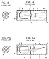
- a conventional streak tube has a structure as shown in FIGS. 1A, 1B, 2A and 2B of the accompanying drawings.
- FIG. 1A is a cross-sectional view showing the streak tube, taken along a plane parallel to deflection electrodes
- FIG. 1B is a diagram showing the relationship between a photocathode and an optical image formed thereon in the streak tube shown in FIG. 1A
- FIG. 2A is a cross-sectional view showing the streak tube, taken along a plane including the axis of the streak tube and perpendicular to the deflection electrodes
- FIG. 2B is a diagram view showing the relationship between a photocathode and an optical image formed thereon in FIG. 2A.
- FIGS. 1A is a cross-sectional view showing the streak tube, taken along a plane parallel to deflection electrodes
- FIG. 1B is a diagram showing the relationship between a photocathode and an optical image formed thereon in the streak tube shown in FIG. 1A
- FIG. 2A is a cross-sectional view showing the streak tube, taken along a plane including the axis of the streak tube and perpendic
- the streak tube generally denoted by reference numeral 1
- the streak tube includes a hermetic vacuum casing 2 which has an input window 3 on one end of the casing 2, for focusing thereon an optical image to be analyzed, and an output window 4 on the other end of the casing 2, for emitting the processed optical image out of the casing 2.
- a photocathode 5 Between the input and output windows 3, 4, there are successively disposed, along the axis of the streak tube 1, a photocathode 5, an acceleration mesh electrode 6, a focusing electrode 7, an aperture electrode 8, deflection electrodes 9, and a phosphor screen 10. Progressively higher voltages are applied to the focusing electrode 7, the mesh electrode 6, and the aperture electrode 8 in the stated order with respect to the photocathode 5. The same potential as that of the aperture electrode 8 is applied to the phosphor screen 10.
- An optical image 11 is projected from a device (not shown) onto the photocathode 5 through the input window 3 on a line passing through the center of the photocathode 5.
- the photocathode 5 then emits an image of electrons corresponding to the optical image.
- the emitted electrons are accelerated by the mesh electrode 6, focused by the focusing electrode 7, pass through the aperture electrode 8, and enter the gap between the deflection electrodes 9.
- a ramp deflection voltage is applied between the deflection electrodes 9 to produce a deflection electric field that deflects the electron image.
- the deflected electron image is applied to the phosphor screen 10.
- the electric field generated by the deflection voltage is directed perpendicularly to both the tube axis and the linear electron image, i.e., perpendicularly to the sheet of drawing in the case of FIG. 1A, and parallel to the sheet of drawing in the case of FIG. 2A.
- the intensity of the electric field is proportional to the deflection voltage.
- the linear electron beam is scanned in a direction perpendicular to the longitudinal direction of the linear electron beam and an optical image, referred to as a streaked image, is formed on the phosphor screen 10.
- the streaked image is an array of images that are in the time domain of the linear optical image on the photocathode 5 and are arranged in the direction perpendicular to the linear optical image. Therefore, any change in the brightness of the streaked image along its image array, i.e., in the direction in which it is swept, is representative of a time-dependent change in the intensity of the optical image 11.
- the photoelectrons emitted from the photocathode have various energies. Therefore, the photoelectrons that have simultaneously been emitted from the photocathode 5 reach the deflection electrodes 9 at different times, resulting in a travel time spread of the photoelectrons.
- the travel time spread is partly responsible for a limited time resolution of the streak tube 1.
- the energy distribution of the photoelectrons emitted from the photocathode is determined by the type of the photocathode and the wavelength of the light to be measured, and the acceleration of the photoelectrons is determined by a distribution of potentials along the tube axis from the photocathode to the deflection electrodes. Consequently, the travel time spread is determined by the type of the photocathode, the wavelength of the light to be measured, and the potential distribution along the axis of the streak tube.
- the acceleration mesh electrode is disposed in proximity with the photocathode to accelerate the photoelectrons quickly for thereby minimizing a region in which the photoelectrons travel at low speed in the vicinity of the photocathode.
- the travel time spread between the photocathode and the mesh electrode is determined by only the electric field therebetween once the type of the photocathode used and the wavelength of the light to be measured are given.
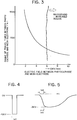
- FIG. 3 shows the relationship between the electric field and the travel time spread when the wavelength of the light to be measured is 500 nm with the use of a photocathode S-20 according to the standards of Electronic Mechanical Industrial Association of the United States. Study of FIG. 3 indicates that theoretically, the travel time spread can be reduced to any desired level if the electric field is increased. Actually, however, when the surface of the photocathode is in a potential of 6 kV/mm or higher, the photocathode emits a dark current due to the field emission effect even if no incident light is applied to the photocathode, thereby increasing noise-induced background emission on the output phosphor screen and thus degrading a signal-to-noise ratio.
- the photocathode has a minute surface projection thereon, then there is developed a very strong electric field on the surface of the photocathode.
- the photocathode produces a very large dark current due to the tunnel effect, and the dark current induces a white spot on the output phosphor screen.
- the background emission on the output phosphor screen may be reduced by applying a voltage between the photocathode and the mesh electrode for a very short period of time, thereby reducing the time in which any dark current is generated.
- a short pulse voltage as shown in FIG. 4 may be applied to the photocathode through flange electrodes which support the input window on which the photocathode is mounted.
- the distance between the photocathode and the acceleration electrode in the conventional streak tube cannot be reduced to 0.5 mm or less.
- the distance therebetween is set in such a manner that upon interposing a spacer of a predetermined thickness between the photocathode and the acceleration electrode, the latter is welded to supporting portions extending from the outer wall of the streak tube. With such a setting, a high assembling accuracy cannot be attained due to the deformation of the electrode resulting from the presence of the spacer and the welding.
- a streak tube comprising an elongate glass bulb having a longitudinal axis and having two open ends opposite to each other; an input window attached to one open end of said glass bulb, said input window having a first surface to which light is applied and which is directed outwardly of said glass bulb and a second surface directed inwardly of said glass bulb; an output window attached to another open end of said glass bulb, said output window having a surface directed inwardly of said glass bulb, said glass bulb, said input window, and said output window defining an hermetic vacuum casing; a phosphor screen formed on the surface of said output window; a photocathode disposed inside the vacuum casing for emitting a photoelectron beam in response to the light applied to the first surface of said input window; a first acceleration electrode disposed in confronting relation to said photocathode for accelerating the photoelectron beam emitted from said photocathode, deflection means for deflecting the photoelectron beam to form a streaked image
- An advantage of the present invention is the provision of a streak tube which allows a pulse voltage having a very short pulse duration to be applied between a photocathode and an acceleration electrode while preventing the pulse voltage from becoming less sharp in waveform and also from dropping.
- a process for manufacturing a streak tube having an input window with a second inner surface and an acceleration electrode contained with a glass bulb includes the steps of: placing the second surface of said input window spaced apart from said acceleration electrode by a distance ranging from 10 to 20 mm; forming said photocathode on the second surface of said input window; finely adjusting a position of the interactive region of said photocathode relative to the interactive region of said acceleration electrode to be spaced apart by a distance equal to or less than 0.5 mm; and, bonding said input window and the one open end of said glass bulb.
- An advantage of the second aspect of this invention is that the photocathode and the acceleration electrode are spaced from each other by a distance which is much smaller than heretofore and are assembled with high accuracy, so that a required electric field can be produced between the photocathode and the acceleration electrode without having to applying a high pulse voltage.
- the streak tube according to the present invention can generate a streaked image with a very high time resolution without an increase in the background emission on an output phosphor screen.
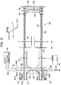
- a photocathode 22 in a streak tube 20 is formed on a strip transmission line 24.
- the streak tube 20 has an input window 26 comprising a glass panel that is convex into one end of a glass bulb 32 of the streak tube 20.
- the photocathode 22 is disposed on an inner end surface 27 of the glass panel that projects into the glass bulb 32.
- the strip transmission line 24 is in the form of an evaporated film of gold deposited on the inner end surface of the input window 26, the evaporated film of gold having a width of 5 mm.
- the strip transmission line 24 includes a gold-film-free area 25 at the center of the input window 26, the gold-film-free area 25 having a size of 0.5 mm ⁇ 0.5 mm.
- a semitransparent tungsten base layer 28 in the pattern of a square having a size greater than the size of 0.5 mm ⁇ 0.5 mm, with peripheral edges overlapping the surrounding evaporated film of gold.
- the photocathode 22 is disposed on the tungsten base layer 28.
- the strip transmission line 24 extends diametrically across the inner end surface 27 of the input window 26.
- Sealed leads 30A, 30B are connected respectively to the opposite ends of the strip transmission line 24.
- the sealed leads 30A, 30B have ends projecting radially outwardly from a glass bulb 32 of the streak tube 20 and connected respectively to cores 34A of coaxial cables 34 which have an impedance of 50 ⁇ .
- One of the coaxial cables 34 is connected to the output terminal of a pulse voltage generator 36, while the other coaxial cable 34 is connected to a resistor of 50 ⁇ that is grounded.
- Each of the coaxial cables 34 has an outer shield 34B that is coupled to an acceleration electrode 38 in the glass bulb 32.
- the streak tube 20 has an output window 40 on the end of the glass bulb 32 remote from the input window 26. Between the acceleration electrode 38 and the output window 40, there are disposed a focusing electrode 42, an anode 44, deflection electrodes 46, and a microchannel plate (MCP) 48 in the glass bulb 32.
- the output window 40 has a phosphor screen 50 in its inner surface.
- a wall electrode 52 is disposed on the inner surface of the glass bulb 32 between the anode 44 and the microchannel plate 48.
- the microchannel plate 48 has an MCP input electrode 54 and an MCP output electrode 56.
- the input window 26 is supported by a support cylinder 58 having a peripheral flange 58A that is supported on the end of the glass bulb 32 by bellows 60.
- the end of the glass bulb 32 and the flange 58A are spaced from each other by a spacer 62.
- the inner end surface 27 of the input window 26 and the acceleration electrode 38 are spaced from each other by a distance ranging from 10 to 20 mm. Then, an evaporation source of antimony, from which the photocathode will be formed, is introduced into the glass bulb 32 through a photocathode fabrication tip 64. An antimony layer is evaporated on the tungsten base layer 28, and an alkaline metal vapor is also introduced into the glass bulb 32, thereby forming an S-20 photocathode 22 on the tungsten base layer 28.
- the bellows 60 is contracted and fine adjustments are made to keep the photocathode 22 and the acceleration electrode 38 spaced from each other by a distance equal to or less than 0.5 mm. If the distance is, for example, adjusted to 0.2 mm, then the spacer 62 is placed between the flange 58A and a flange 60A of the bellows 60 and bonded thereto by adhesive. The distance between the photocathode 22 and the acceleration electrode 38 is thus set to 0.2 mm.
- the acceleration electrode 38 is of a frustoconical shape projecting toward the photocathode 22 and has a hollow inner space.
- a circular mesh having a mesh size of 1000 mesh/inch (40 mesh/mm) is bonded to the tip end of the frustoconical acceleration electrode 38.
- a voltage of + 15 kV is applied to the focusing electrode 42, and a voltage of 0 V is applied to each of the acceleration electrode 38, the wall electrode 52, and the MCP electrode 54.
- a voltage of + 800 V is applied to the MCP output electrode 56, and a voltage of + 3.8 kV is applied to the phosphor screen 50.
- a pulse voltage is applied from the pulse voltage generator 36 to the photocathode 22 only during a period of streaking operation, and a voltage of 0 V is applied to the photocathode 22 when no streaking operation is effected (see FIG. 8).
- the pulse voltage generator 36 generates a pulse voltage as shown in FIG. 8, and the generated pulse voltage is applied to the photocathode 22 through the coaxial cable 34, the sealed lead 30A, and the strip transmission line 24. At this time, the pulse voltage is of - 3 kV and has a duration of 1 ns. The pulse voltage is drained to ground through the other sealed lead 30B and the resistor of 50 ⁇ .
- the pulse voltage Since the pulse voltage is applied through the strip transmission line 24 that is impedance-matched, the pulse voltage does not suffer any voltage loss which would otherwise be caused by waveform deformations and reflections.
- the photocathode 22 and the acceleration electrode 38 thus develop therebetween a high-speed pulsed electric field corresponding to the voltage generated by the pulse voltage generator 36.
- the distance between the photocathode 22 and the acceleration electrode 38 is set to 0.2 mm. Therefore, the intensity of the electric field produced by the pulse voltage of - 3 kV has a very large value of 15 kV/mm, thereby strongly accelerating photoelectrons emitted from the photocathode 22. Accordingly, any travel time spread of the photoelectrons due to an initial speed distribution in the emission from the photocathode 22 is minimized. Since the pulse voltage is applied to the photocathode 22 in a very short time of 1 ns, any dark current produced under the high electric field developed by the pulse voltage is negligibly small.
- the photoelectrons emitted from the photocathode 22 and accelerated by the acceleration electrode 38 are focused onto the input surface of the microchannel plate 48 by the focusing electrode 42 to which the voltage of 15 kV is applied. Inasmuch as the high positive voltage is applied to the focusing electrode 42, thus forming an electric focusing lens, the travel time spread of the photoelectrons is small in the focusing electrode 42.
- the photoelectron beam is swept by the deflection electrodes 46, multiplied by the microchannel plate 48, and applied to the output phosphor screen 50 on which a streaked image is formed.
- the streak tube 20 has 100 fs order time resolution. Since the distance between the photocathode 22 and the acceleration electrode 38 can be set to a value smaller than manufacturing errors using the bellows 60, a high electric field can be developed and emitted photoelectrons can be quickly accelerated without the application of a higher voltage.
- the photocathode 22 is formed on the impedance-matched strip transmission line 24, part of the pulse voltage wave applied through the strip transmission line 24 to the photocathode 22 is not reflected, and a desired ultrashort and very intensive pulsed electric field can be developed between the photocathode 22 and the acceleration electrode 38.
- the distance between the photocathode 22 and the acceleration electrode 38 is set to a value smaller than manufacturing errors through fine adjustments using the bellows 60 after the photocathode 22 is formed.
- the present invention is not limited to the above arrangement, but the distance between the photocathode 22 and the acceleration electrode 38 may be minimized by other means or with increased fabrication accuracy.
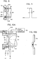
- indium may be employed as in a second embodiment shown in FIG. 9.
- the input window 26 of a streak tube 66 is affixed in position by a member 68 of indium. More specifically, a flange 70 is attached to an end face of a glass bulb 32 of a streak tube 66, and the indium member 68 is disposed in a radially inner recess 72 defined in the flange 70 at a lefthand end surface thereof as shown.
- the larger-diameter inner surface 26A of the input window 26 is brought into intimate contact with the inner top face 72B of the flange 70, wherein a distance between the photocathode 22 and the acceleration electrode 38 is set to be, for example, 0.15 mm.
- the indium member 68 Since the indium member 68 is soft in property, it can easily be deformed to allow the distance between the photocathode 22 and the acceleration electrode 38 to be set as described above. Accordingly, the distance between the photocathode 22 and the acceleration electrode 38 can be minutely reduced as desired with high accuracy.
- the inner flange portion serving as a stopper at the time of compression of the indium member may not be provided. In such a case, a tool or machine may stop performing the indium sealing when it is detected that the distance between the photocathode 22 and the acceleration electrode 38 is equal to a desired value.
- FIGS. 10A and 10B A third embodiment of the present invention will be described below with reference to FIGS. 10A and 10B.
- a streak tube 73 according to the third embodiment has an acceleration electrode 74 mounted on a strip transmission line 76, and the shields 34B of the coaxial cables 34 are connected to the photocathode 22.
- the acceleration electrode 74 is in the form of a mesh disposed in a hole, which has a size of 0.5 ⁇ 0.5 mm, for example, defined in a central region of the strip transmission line 76 which is of a trapezoidal cross section projecting toward the photocathode 22, the acceleration electrode 74 confronting the photocathode 22.
- a DC voltage of - 3 kV is applied to the photocathode 22.
- the pulse voltage generator 36 is biased by - 3 kV to generate a positive pulse voltage of 3 kV whose duration is 1 ns, as shown in FIG. 11.
- a streak tube 77 according to the fourth embodiment is of substantially the same structure as that of the first embodiment shown in FIG. 6, except for an additional second acceleration electrode 78.
- the second acceleration electrode 78 comprises a mesh that is spaced from the acceleration electrode 38 by 5 mm, for example, and a positive DC voltage of 20 kV is applied to the second acceleration electrode 78.
- the other structural details of the fourth embodiment are the same as those of the first embodiment, and those parts of the fourth embodiment which are identical to those of the first embodiment are denoted by identical reference numerals and thus the description thereof is omitted.
- the photoelectrons accelerated under the pulsed electric field developed between the photocathode 22 and the acceleration electrode 38 are further accelerated under the DC voltage of + 20 kV applied to the second acceleration electrode 78, to a speed corresponding to the high DC voltage of + 20 kV. Consequently, the travel time spread of the photoelectrons past the acceleration electrodes is reduced.
- the voltage of + 20 kV applied to the second acceleration electrode 78 is high, it can easily be generated as it is a DC voltage.
- the second acceleration electrode 78 is spaced from the acceleration electrode 38 by a relatively large distance.
- the electric field developed between the second acceleration electrode 78 and the acceleration electrode 38 is of a relatively low value of 4 kV/mm. Therefore, the background emission is not increased under the electric field developed between the second acceleration electrode 78 and the acceleration electrode 38.
- each of the acceleration electrodes is in the form of a mesh.
- an acceleration electrode may have a slit 80 parallel to the deflection electrodes 46, the slit 80 having a length of 1 mm and a width of about 30 ⁇ m, for example.
- an acceleration electrode may have an aperture having a diameter of 0.5 mm. If the acceleration electrode with a slit or an aperture is employed, the dark current that has been produced is blocked by the other region of the acceleration electrode than the slit or the aperture through which the photoelectrons pass, so that the background emission is prevented from increasing.
- the acceleration electrode 78 shown in FIG. 12 may also have a slit or aperture. If the acceleration electrode has only a slit or an aperture, then the electric potential tends to be disturbed. To avoid this, the acceleration electrode may have a fine mesh disposed in superposed relationship to the slit or the aperture.
- deflection electrodes 84 are disposed near the second acceleration electrode 78 in a streak tube 82.
- a focusing coil 86 is positioned behind the deflection electrodes 84.
- the distance between the photocathode 22 and the acceleration electrode 38 is 0.08 mm
- the distance between the acceleration electrode 38 and the second acceleration electrode 78 is 4 mm
- the distance between the second acceleration electrode 78 and the deflection electrodes 84 is 3 mm.
- the acceleration electrode 38 comprises a mesh
- the second electrode 78 has an aperture defined therein.
- the deflection electrodes are spaced from the photocathode by several tens mm or more, the travel time spread of the photoelectrons due to an initial speed distribution or a space charge effect is not negligible.
- a very intensive pulsed electric field is developed between the photocathode and the acceleration electrode to reduce the travel time spread during an initial period, and the deflection electrodes 84 are disposed immediately behind the second acceleration electrode 78 for more effectively reducing the travel time spread.
- a pulse voltage When a pulse voltage is applied to the photocathode 22 by the pulse voltage generator 36, a very intensive pulsed electric field of 37.5 kV/mm is developed between the photocathode 22 and the acceleration electrode 38 for 1 ns.
- the photoelectrons that have been accelerated by the pulsed electric field are further accelerated by the second acceleration electrode 37, and then immediately deflected by the deflection electrodes 84.
- a ramp voltage that varies from + 1.5 kV to - 1.5 kV for 200 ps is applied to one of the deflection electrodes 84, and a ramp voltage that varies from - 1.5 kV to + 1.5 kV for 200 ps is applied to the other deflection electrode 84.
- the photoelectrons After having been deflected by the deflection electrodes 84, the photoelectrons are focused as a streaked image on the phosphor screen 50 by the focusing coil 86.
- a time resolution of 50 fs is achieved when the photoelectrons are deflected by the deflection electrodes 84 immediately after they have been accelerated by the acceleration electrode 38 and the second acceleration electrode 78.
- the distance between the photocathode and the acceleration electrode is adjusted to a desired small value using the bellows or the indium member.
- the present invention is not limited to such an arrangement.
- the distance between the photocathode and the acceleration electrode may further be reduced by increased fabrication accuracy.
- the photocathode or the acceleration electrode is formed on the strip transmission line in the above embodiments.
- the photocathode or the acceleration electrode may be formed on a strip-like electrode which is impedance-matched and can generate a very short and very intensive pulsed electric field between the photocathode and the acceleration electrode with a relatively low pulse voltage.
- the strip transmission line or the strip-like electrode may vary in width in order to uniformize the impedance with respect to the acceleration electrode or the photocathode which confronts the strip transmission line or the strip-like electrode.
- both of the photocathode and the acceleration electrode may be formed on the strip transmission line or the strip-like electrode.
Landscapes
- Image-Pickup Tubes, Image-Amplification Tubes, And Storage Tubes (AREA)
- Photometry And Measurement Of Optical Pulse Characteristics (AREA)
Applications Claiming Priority (2)
| Application Number | Priority Date | Filing Date | Title |
|---|---|---|---|
| JP238457/90 | 1990-09-07 | ||
| JP2238457A JP3071809B2 (ja) | 1990-09-07 | 1990-09-07 | ストリーク管 |
Publications (2)
| Publication Number | Publication Date |
|---|---|
| EP0474502A1 true EP0474502A1 (de) | 1992-03-11 |
| EP0474502B1 EP0474502B1 (de) | 1995-05-10 |
Family
ID=17030512
Family Applications (1)
| Application Number | Title | Priority Date | Filing Date |
|---|---|---|---|
| EP91308161A Expired - Lifetime EP0474502B1 (de) | 1990-09-07 | 1991-09-06 | Streakkamera mit einer Einrichtung zur Unterdrückung der Laufzeitunterschiede von Photoelektronen |
Country Status (4)
| Country | Link |
|---|---|
| US (1) | US5221836A (de) |
| EP (1) | EP0474502B1 (de) |
| JP (1) | JP3071809B2 (de) |
| DE (1) | DE69109586T2 (de) |
Families Citing this family (10)
| Publication number | Priority date | Publication date | Assignee | Title |
|---|---|---|---|---|
| LU87882A1 (fr) * | 1991-01-30 | 1992-10-15 | Europ Communities | Camera ultrarapide pour visualiser le profil d'intensite d'une impulsion laser |
| US5278403A (en) * | 1991-04-29 | 1994-01-11 | Alfano Robert R | Femtosecond streak camera |
| USH1979H1 (en) | 1998-08-31 | 2001-08-07 | The United States Of America As Represented By The Secretary Of The Air Force | Electronic streak camera |
| US6642499B1 (en) | 1999-07-19 | 2003-11-04 | The University Of Rochester | System for photometric calibration of optoelectronic imaging devices especially streak cameras |
| JP4268461B2 (ja) * | 2003-06-24 | 2009-05-27 | 浜松ホトニクス株式会社 | 時間分解測定装置 |
| WO2008086439A1 (en) | 2007-01-09 | 2008-07-17 | Visa U.S.A. Inc. | Contactless transaction |
| FR2917836B1 (fr) * | 2007-06-20 | 2009-09-18 | Cnes Epic | Dispositif d'analyse de repartition de charges dans un element dielectrique |
| JP5824328B2 (ja) | 2011-10-31 | 2015-11-25 | 浜松ホトニクス株式会社 | ストリーク管及びそれを含むストリーク装置 |
| JP5824329B2 (ja) | 2011-10-31 | 2015-11-25 | 浜松ホトニクス株式会社 | ストリーク管 |
| JP6613466B2 (ja) * | 2014-10-28 | 2019-12-04 | 国立研究開発法人量子科学技術研究開発機構 | 荷電粒子ビーム照射装置 |
Citations (2)
| Publication number | Priority date | Publication date | Assignee | Title |
|---|---|---|---|---|
| EP0315435A2 (de) * | 1987-11-04 | 1989-05-10 | Imco Electro-Optics Limited | Bildwandlerröhre zur Aufnahme von mit hoher Geschwindigkeit ablaufenden Vorgängen |
| US4902927A (en) * | 1987-05-01 | 1990-02-20 | Hamamatsu Photonics Kabushiki Kaisha | Streak tube |
Family Cites Families (3)
| Publication number | Priority date | Publication date | Assignee | Title |
|---|---|---|---|---|
| US3863087A (en) * | 1973-09-20 | 1975-01-28 | Burroughs Corp | Display panel having an array of insulated strip electrodes |
| DE3884490T2 (de) * | 1987-07-14 | 1994-01-27 | Hamamatsu Photonics Kk | Einrichtung zum Abtasten, Analysieren und Anzeigen eines elektrischen Signals. |
| GB2226693B (en) * | 1988-12-28 | 1993-09-01 | Hamamatsu Photonics Kk | Optical waveform observing apparatus |
-
1990
- 1990-09-07 JP JP2238457A patent/JP3071809B2/ja not_active Expired - Fee Related
-
1991
- 1991-09-06 US US07/755,976 patent/US5221836A/en not_active Expired - Fee Related
- 1991-09-06 EP EP91308161A patent/EP0474502B1/de not_active Expired - Lifetime
- 1991-09-06 DE DE69109586T patent/DE69109586T2/de not_active Expired - Fee Related
Patent Citations (2)
| Publication number | Priority date | Publication date | Assignee | Title |
|---|---|---|---|---|
| US4902927A (en) * | 1987-05-01 | 1990-02-20 | Hamamatsu Photonics Kabushiki Kaisha | Streak tube |
| EP0315435A2 (de) * | 1987-11-04 | 1989-05-10 | Imco Electro-Optics Limited | Bildwandlerröhre zur Aufnahme von mit hoher Geschwindigkeit ablaufenden Vorgängen |
Non-Patent Citations (1)
| Title |
|---|
| REVIEW OF SCIENTIFIC INSTRU- MENTS, vol. 58, No. 6, June 1987 K. KINOSHITA et al. "Femtosecond streak tube" pages 932-938 * |
Also Published As
| Publication number | Publication date |
|---|---|
| EP0474502B1 (de) | 1995-05-10 |
| JPH04118530A (ja) | 1992-04-20 |
| JP3071809B2 (ja) | 2000-07-31 |
| DE69109586T2 (de) | 1995-09-07 |
| US5221836A (en) | 1993-06-22 |
| DE69109586D1 (de) | 1995-06-14 |
Similar Documents
| Publication | Publication Date | Title |
|---|---|---|
| US4955681A (en) | Image display apparatus having sheet like vertical and horizontal deflection electrodes | |
| US4120002A (en) | Streak camera tube | |
| EP0474502B1 (de) | Streakkamera mit einer Einrichtung zur Unterdrückung der Laufzeitunterschiede von Photoelektronen | |
| EP1253618B1 (de) | Streak vorrichtung | |
| EP0430718B1 (de) | Streakkamera | |
| JP2572388B2 (ja) | ストリ−ク管 | |
| US4595375A (en) | Imaging and streaking tubes, and methods for fabricating the imaging and streaking tubes | |
| US4677341A (en) | Synchronous scan streaking device | |
| JPS58145B2 (ja) | 電子ビ−ムシヤツタ装置 | |
| JPS5858007B2 (ja) | ストリ−ク管 | |
| EP0084915B1 (de) | Fernsehkameraröhre | |
| JPS61250946A (ja) | ストリーク管およびストリーク装置 | |
| JP2948621B2 (ja) | ストリーク管 | |
| JP2813010B2 (ja) | ストリーク管 | |
| JPH06241895A (ja) | ストリーク装置 | |
| JPS5858006B2 (ja) | ストリ−ク管 | |
| JP2527735B2 (ja) | ストリ−ク装置 | |
| JP3002221B2 (ja) | 走査プローブ型顕微鏡 | |
| JPS5858005B2 (ja) | ストリ−ク管 | |
| GB2116359A (en) | Streak tubes | |
| JPH0623669B2 (ja) | ストリ−ク装置 | |
| GB2149200A (en) | Imaging and streaking tubes | |
| JPH10134763A (ja) | 電子増倍器 | |
| GB2027983A (en) | Streak camera tubes | |
| JPS6276141A (ja) | X線イメ−ジインテンシフアイア |
Legal Events
| Date | Code | Title | Description |
|---|---|---|---|
| PUAI | Public reference made under article 153(3) epc to a published international application that has entered the european phase |
Free format text: ORIGINAL CODE: 0009012 |
|
| AK | Designated contracting states |
Kind code of ref document: A1 Designated state(s): DE FR GB |
|
| 17P | Request for examination filed |
Effective date: 19920909 |
|
| 17Q | First examination report despatched |
Effective date: 19940614 |
|
| GRAA | (expected) grant |
Free format text: ORIGINAL CODE: 0009210 |
|
| AK | Designated contracting states |
Kind code of ref document: B1 Designated state(s): DE FR GB |
|
| REF | Corresponds to: |
Ref document number: 69109586 Country of ref document: DE Date of ref document: 19950614 |
|
| ET | Fr: translation filed | ||
| PLBE | No opposition filed within time limit |
Free format text: ORIGINAL CODE: 0009261 |
|
| STAA | Information on the status of an ep patent application or granted ep patent |
Free format text: STATUS: NO OPPOSITION FILED WITHIN TIME LIMIT |
|
| 26N | No opposition filed | ||
| PGFP | Annual fee paid to national office [announced via postgrant information from national office to epo] |
Ref country code: DE Payment date: 20000828 Year of fee payment: 10 |
|
| PGFP | Annual fee paid to national office [announced via postgrant information from national office to epo] |
Ref country code: GB Payment date: 20000906 Year of fee payment: 10 |
|
| PG25 | Lapsed in a contracting state [announced via postgrant information from national office to epo] |
Ref country code: GB Free format text: LAPSE BECAUSE OF NON-PAYMENT OF DUE FEES Effective date: 20010906 |
|
| PG25 | Lapsed in a contracting state [announced via postgrant information from national office to epo] |
Ref country code: DE Free format text: LAPSE BECAUSE OF NON-PAYMENT OF DUE FEES Effective date: 20020501 |
|
| PGFP | Annual fee paid to national office [announced via postgrant information from national office to epo] |
Ref country code: FR Payment date: 20050823 Year of fee payment: 15 |
|
| REG | Reference to a national code |
Ref country code: FR Ref legal event code: ST Effective date: 20070531 |
|
| PG25 | Lapsed in a contracting state [announced via postgrant information from national office to epo] |
Ref country code: FR Free format text: LAPSE BECAUSE OF NON-PAYMENT OF DUE FEES Effective date: 20061002 |