EP0474007A2 - Dispositif accélérateur pour turboprocesseur de moteur diesel - Google Patents
Dispositif accélérateur pour turboprocesseur de moteur diesel Download PDFInfo
- Publication number
- EP0474007A2 EP0474007A2 EP91113836A EP91113836A EP0474007A2 EP 0474007 A2 EP0474007 A2 EP 0474007A2 EP 91113836 A EP91113836 A EP 91113836A EP 91113836 A EP91113836 A EP 91113836A EP 0474007 A2 EP0474007 A2 EP 0474007A2
- Authority
- EP
- European Patent Office
- Prior art keywords
- run
- control slide
- exhaust gas
- turbine
- steam
- Prior art date
- Legal status (The legal status is an assumption and is not a legal conclusion. Google has not performed a legal analysis and makes no representation as to the accuracy of the status listed.)
- Withdrawn
Links
Images

Classifications
-
- F—MECHANICAL ENGINEERING; LIGHTING; HEATING; WEAPONS; BLASTING
- F02—COMBUSTION ENGINES; HOT-GAS OR COMBUSTION-PRODUCT ENGINE PLANTS
- F02B—INTERNAL-COMBUSTION PISTON ENGINES; COMBUSTION ENGINES IN GENERAL
- F02B37/00—Engines characterised by provision of pumps driven at least for part of the time by exhaust
- F02B37/04—Engines with exhaust drive and other drive of pumps, e.g. with exhaust-driven pump and mechanically-driven second pump
- F02B37/10—Engines with exhaust drive and other drive of pumps, e.g. with exhaust-driven pump and mechanically-driven second pump at least one pump being alternatively or simultaneously driven by exhaust and other drive, e.g. by pressurised fluid from a reservoir or an engine-driven pump
-
- F—MECHANICAL ENGINEERING; LIGHTING; HEATING; WEAPONS; BLASTING
- F01—MACHINES OR ENGINES IN GENERAL; ENGINE PLANTS IN GENERAL; STEAM ENGINES
- F01N—GAS-FLOW SILENCERS OR EXHAUST APPARATUS FOR MACHINES OR ENGINES IN GENERAL; GAS-FLOW SILENCERS OR EXHAUST APPARATUS FOR INTERNAL-COMBUSTION ENGINES
- F01N5/00—Exhaust or silencing apparatus combined or associated with devices profiting by exhaust energy
- F01N5/02—Exhaust or silencing apparatus combined or associated with devices profiting by exhaust energy the devices using heat
-
- F—MECHANICAL ENGINEERING; LIGHTING; HEATING; WEAPONS; BLASTING
- F02—COMBUSTION ENGINES; HOT-GAS OR COMBUSTION-PRODUCT ENGINE PLANTS
- F02B—INTERNAL-COMBUSTION PISTON ENGINES; COMBUSTION ENGINES IN GENERAL
- F02B33/00—Engines characterised by provision of pumps for charging or scavenging
- F02B33/44—Passages conducting the charge from the pump to the engine inlet, e.g. reservoirs
-
- F—MECHANICAL ENGINEERING; LIGHTING; HEATING; WEAPONS; BLASTING
- F02—COMBUSTION ENGINES; HOT-GAS OR COMBUSTION-PRODUCT ENGINE PLANTS
- F02B—INTERNAL-COMBUSTION PISTON ENGINES; COMBUSTION ENGINES IN GENERAL
- F02B37/00—Engines characterised by provision of pumps driven at least for part of the time by exhaust
- F02B37/02—Gas passages between engine outlet and pump drive, e.g. reservoirs
-
- F—MECHANICAL ENGINEERING; LIGHTING; HEATING; WEAPONS; BLASTING
- F02—COMBUSTION ENGINES; HOT-GAS OR COMBUSTION-PRODUCT ENGINE PLANTS
- F02B—INTERNAL-COMBUSTION PISTON ENGINES; COMBUSTION ENGINES IN GENERAL
- F02B37/00—Engines characterised by provision of pumps driven at least for part of the time by exhaust
- F02B37/04—Engines with exhaust drive and other drive of pumps, e.g. with exhaust-driven pump and mechanically-driven second pump
-
- F—MECHANICAL ENGINEERING; LIGHTING; HEATING; WEAPONS; BLASTING
- F02—COMBUSTION ENGINES; HOT-GAS OR COMBUSTION-PRODUCT ENGINE PLANTS
- F02B—INTERNAL-COMBUSTION PISTON ENGINES; COMBUSTION ENGINES IN GENERAL
- F02B3/00—Engines characterised by air compression and subsequent fuel addition
- F02B3/06—Engines characterised by air compression and subsequent fuel addition with compression ignition
-
- Y—GENERAL TAGGING OF NEW TECHNOLOGICAL DEVELOPMENTS; GENERAL TAGGING OF CROSS-SECTIONAL TECHNOLOGIES SPANNING OVER SEVERAL SECTIONS OF THE IPC; TECHNICAL SUBJECTS COVERED BY FORMER USPC CROSS-REFERENCE ART COLLECTIONS [XRACs] AND DIGESTS
- Y02—TECHNOLOGIES OR APPLICATIONS FOR MITIGATION OR ADAPTATION AGAINST CLIMATE CHANGE
- Y02T—CLIMATE CHANGE MITIGATION TECHNOLOGIES RELATED TO TRANSPORTATION
- Y02T10/00—Road transport of goods or passengers
- Y02T10/10—Internal combustion engine [ICE] based vehicles
- Y02T10/12—Improving ICE efficiencies
Definitions
- the invention relates to a ramp-up device for an exhaust gas turbocharger of a diesel engine, with a supercharger turbine and an upstream tubular control slide, wherein a gas supply housing of the charger turbine is separated into an inner gas supply duct and an outer gas supply duct, which is gas-tightly separable from the control slide.
- Turbochargers for diesel engines which are operated with the exhaust gases of the engine which arise during combustion, for example depending on the load (DE-PS 37 15 729), in order to achieve an increase in the filling and thus an increase in engine performance. Furthermore, turbochargers have become known in which an increase in the boost pressure and the delivery rate is achieved by external charging, in that the compressor of the charger is driven by an auxiliary motor. Training of this type are relatively complex.
- turbochargers are either only to be operated with a complex auxiliary drive, which is additionally required for this purpose, or the energy required to drive the compressor is taken from the exhaust gases, provided that the engine can apply this energy, for example, when idling.
- auxiliary drive which is additionally required for this purpose
- the engine can apply this energy, for example, when idling.
- Auxiliary drives are driven by an additionally operated motor.
- the object of the invention is to provide a run-up device for a turbocharger of a diesel engine of the generic type which ensures a maximum speed of the turbine in a simple manner with an additional energy source when the engine is idling or at a standstill.
- control slide enables a separation from the exhaust system of the engine during the start-up phase. Furthermore, a small area of the supercharger turbine can be used to maintain the required back pressure and the arrangement does not make the compressor unstable.
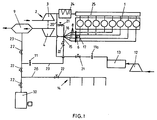
- the run-up device shown is provided for an arrangement which essentially consists of a turbocharger 2 with a compressor 3 and a turbine 4 arranged on the same shaft, which can be driven by exhaust gases from the diesel engine 1.
- a tubular control slide 6 with a controllable drive 17 is arranged downstream, which permits supply of the exhaust gases via an exhaust gas supply housing 5 to the turbine 4 in accordance with the desired charging requirements.
- the exhaust gas feed housing 5 to the turbine 4 is provided with an inner and outer feed channel 27, 28, the control slide 6 separating the inner feed channel 27 in one end position.
- the run-up device shown can preferably be used for ships, an exhaust gas boiler 9 being connected to an auxiliary boiler 10 via lines 23 and for driving the turbine 4 of the turbocharger 2, that a steam network 14 can be connected to the thermal energy supply device and steam is supplied via the lines 26, 23 becomes.
- a pressure reducer 11 and shut-off valves 22 are arranged in line 23.
- the turbocharger 2 can be ramped up in advance with the engine 1 at a standstill or with the engine idling so that when the engine is started the full charge is immediately processed and an engine torque is available.
- the control slide 6 closes the inner supply channel 27 in the exhaust gas supply housing 2, so that a separation from the exhaust system takes place.
- a charge air cooler 24 which is connected to a charge air receiver 25 of the engine 1, is arranged downstream in a line 20 of the compressor 3 of the turbocharger 2.
- a recirculating air line 20 connects the charge cooler 24 to a compressed air generator 12 and compressed air reservoir 13 to a pressure reducing valve 11a.
- the valves 21 can be used to supply the compressed air via a line 16 and are available for startup.
- a corresponding air / steam chamber 18 is formed, from which a connection to the inner feed channel 27 in the exhaust gas feed housing 2 is made via passage slots 19 in the control slide 6.
Landscapes
- Engineering & Computer Science (AREA)
- Chemical & Material Sciences (AREA)
- Combustion & Propulsion (AREA)
- Mechanical Engineering (AREA)
- General Engineering & Computer Science (AREA)
- Supercharger (AREA)
Applications Claiming Priority (2)
| Application Number | Priority Date | Filing Date | Title |
|---|---|---|---|
| DE4028263 | 1990-09-06 | ||
| DE4028263 | 1990-09-06 |
Publications (2)
| Publication Number | Publication Date |
|---|---|
| EP0474007A2 true EP0474007A2 (fr) | 1992-03-11 |
| EP0474007A3 EP0474007A3 (en) | 1993-04-14 |
Family
ID=6413710
Family Applications (1)
| Application Number | Title | Priority Date | Filing Date |
|---|---|---|---|
| EP19910113836 Withdrawn EP0474007A3 (en) | 1990-09-06 | 1991-08-19 | Running up device for diesel engine turbo charges |
Country Status (1)
| Country | Link |
|---|---|
| EP (1) | EP0474007A3 (fr) |
Cited By (5)
| Publication number | Priority date | Publication date | Assignee | Title |
|---|---|---|---|---|
| WO1997022789A1 (fr) * | 1995-12-19 | 1997-06-26 | Ab Volvo | Dispositif de regulation de la force de frein-moteur dans un moteur a combustion interne |
| WO2005059332A1 (fr) * | 2003-12-18 | 2005-06-30 | Daimlerchrysler Ag | Moteur a combustion interne suralimente |
| US7043913B2 (en) * | 2003-06-23 | 2006-05-16 | Komatsu Ltd. | Turbocharger |
| DE102007025282A1 (de) * | 2007-05-30 | 2008-12-04 | Voith Patent Gmbh | Abgasturbolader |
| US20120279218A1 (en) * | 2009-10-16 | 2012-11-08 | Michiyasu Ishida | Miller cycle engine |
Family Cites Families (4)
| Publication number | Priority date | Publication date | Assignee | Title |
|---|---|---|---|---|
| FR2222537A2 (en) * | 1973-03-21 | 1974-10-18 | France Etat | Throttle control of super-charged diesel engine - regulates air to super-charger combustion chamber and exhaust |
| FR2265979B1 (fr) * | 1974-03-29 | 1977-10-14 | France Etat | |
| DE2840201A1 (de) * | 1978-09-15 | 1980-03-27 | Maschf Augsburg Nuernberg Ag | Vorrichtung zur veraenderung der zustroemquerschnittsflaeche der turbine eines abgasturboladers |
| DE3715729C1 (de) * | 1987-05-12 | 1988-09-08 | Krupp Mak Maschb Gmbh | Turbinengehaeuse fuer einen Abgasturbolader einer Brennkraftmaschine |
-
1991
- 1991-08-19 EP EP19910113836 patent/EP0474007A3/de not_active Withdrawn
Cited By (7)
| Publication number | Priority date | Publication date | Assignee | Title |
|---|---|---|---|---|
| WO1997022789A1 (fr) * | 1995-12-19 | 1997-06-26 | Ab Volvo | Dispositif de regulation de la force de frein-moteur dans un moteur a combustion interne |
| US6085524A (en) * | 1995-12-19 | 2000-07-11 | Ab Volvo | Device for regulating the engine braking power of an internal combustion engine |
| US7043913B2 (en) * | 2003-06-23 | 2006-05-16 | Komatsu Ltd. | Turbocharger |
| CN100374697C (zh) * | 2003-06-23 | 2008-03-12 | 株式会社小松制作所 | 涡轮增压器 |
| WO2005059332A1 (fr) * | 2003-12-18 | 2005-06-30 | Daimlerchrysler Ag | Moteur a combustion interne suralimente |
| DE102007025282A1 (de) * | 2007-05-30 | 2008-12-04 | Voith Patent Gmbh | Abgasturbolader |
| US20120279218A1 (en) * | 2009-10-16 | 2012-11-08 | Michiyasu Ishida | Miller cycle engine |
Also Published As
| Publication number | Publication date |
|---|---|
| EP0474007A3 (en) | 1993-04-14 |
Similar Documents
| Publication | Publication Date | Title |
|---|---|---|
| EP0531277B1 (fr) | Moteur à combustion interne comprenant un système d'admission et d'échappement, un turbocompresseur et un accumutateur de pression | |
| EP1071871B1 (fr) | Turbine de turbosoufflante a gaz d'echappement | |
| DE2503806A1 (de) | Verfahren zum betrieb eines aufgeladenen viertakt-dieselmotors sowie mit dem verfahren betriebener motor | |
| EP2151569B1 (fr) | Dispositif d'extraction d'un flux partiel de gaz d'échappement et moteur à combustion interne en étant équipé | |
| DE19924228A1 (de) | Mehrflutiger, regelbarer Abgasturbolader | |
| DE3133952A1 (de) | Turboladeeinrichtung fuer eine verbrennungskraftmaschine | |
| DE19824766A1 (de) | Gasturbine sowie Verfahren zur Kühlung einer Turbinenstufe | |
| DE102010021449B4 (de) | Verfahren zum Betreiben eines Verbrennungsmotors und Verbrennungsmotor | |
| DE1601624B2 (de) | Durch Verbrennungsgas betriebene Gasturbinenanlage zum Andrehen von Triebwerken | |
| EP1639245A1 (fr) | Moteur a combustion interne comportant un compresseur dans la pipe d'admission et procede correspondant | |
| DE102009050975A1 (de) | Leitvorrichtung für einen Abgasturbolader mit verstellbarer Turbinengeometrie sowie Abgasturbolader für eine Brennkraftmaschine | |
| DE102007060218A1 (de) | Verfahren zum Betreiben eines Verdichters | |
| DE102014221333A1 (de) | Zwillingsturbo-System mit elektrisch antreibbaren Verdichtern | |
| DE3711863C2 (fr) | ||
| DE2818447C2 (de) | Aufladesystem für Brennkraftmaschinen | |
| DE3330315A1 (de) | Antriebsanordnung von nebenaggregaten an einer brennkraftmaschine | |
| DE3224006A1 (de) | Turboaufladegruppe fuer brennkraftmaschinen | |
| DE2435004B2 (de) | Aufgeladene Viertaktbrennkraftmaschine | |
| DE102015214404A1 (de) | Antriebsvorrichtung für ein Kraftfahrzeug, Verfahren zum Betreiben einer Antriebsvorrichtung | |
| DE915635C (de) | Andrehvorrichtung fuer eine Brennkraftmaschine mit einem Abgasturboladegeblaese | |
| DE4215301A1 (de) | Abgasturbolader mit einer Radialturbine | |
| DE3335856C2 (de) | Abgasturboladersystem an einem aufgeladenem Verbrennungsmotor | |
| DE3620682C2 (fr) | ||
| EP0814235B1 (fr) | Turbine radiale pour une turbosoufflante | |
| DE1071412B (de) | Verfahren zum Spülen und Aufladen der Zylinder von Zweitaktbrennkraftmaschinen, insbesondere Zweitaktdieselmotoren, und Einrichtung zur Durchführung dieses Verfahrens |
Legal Events
| Date | Code | Title | Description |
|---|---|---|---|
| PUAI | Public reference made under article 153(3) epc to a published international application that has entered the european phase |
Free format text: ORIGINAL CODE: 0009012 |
|
| AK | Designated contracting states |
Kind code of ref document: A2 Designated state(s): DE DK FR GB IT NL |
|
| PUAL | Search report despatched |
Free format text: ORIGINAL CODE: 0009013 |
|
| AK | Designated contracting states |
Kind code of ref document: A3 Designated state(s): DE DK FR GB IT NL |
|
| 17P | Request for examination filed |
Effective date: 19930503 |
|
| 17Q | First examination report despatched |
Effective date: 19940216 |
|
| STAA | Information on the status of an ep patent application or granted ep patent |
Free format text: STATUS: THE APPLICATION HAS BEEN WITHDRAWN |
|
| 18W | Application withdrawn |
Withdrawal date: 19940819 |