EP0473790B1 - Fil destine a ouvrir une partie obstruee de vaisseau sanguin - Google Patents
Fil destine a ouvrir une partie obstruee de vaisseau sanguin Download PDFInfo
- Publication number
- EP0473790B1 EP0473790B1 EP91904799A EP91904799A EP0473790B1 EP 0473790 B1 EP0473790 B1 EP 0473790B1 EP 91904799 A EP91904799 A EP 91904799A EP 91904799 A EP91904799 A EP 91904799A EP 0473790 B1 EP0473790 B1 EP 0473790B1
- Authority
- EP
- European Patent Office
- Prior art keywords
- wire
- wire body
- distal end
- opening
- spiral element
- Prior art date
- Legal status (The legal status is an assumption and is not a legal conclusion. Google has not performed a legal analysis and makes no representation as to the accuracy of the status listed.)
- Expired - Lifetime
Links
Images

Classifications
-
- A—HUMAN NECESSITIES
- A61—MEDICAL OR VETERINARY SCIENCE; HYGIENE
- A61B—DIAGNOSIS; SURGERY; IDENTIFICATION
- A61B18/00—Surgical instruments, devices or methods for transferring non-mechanical forms of energy to or from the body
- A61B18/18—Surgical instruments, devices or methods for transferring non-mechanical forms of energy to or from the body by applying electromagnetic radiation, e.g. microwaves
- A61B18/20—Surgical instruments, devices or methods for transferring non-mechanical forms of energy to or from the body by applying electromagnetic radiation, e.g. microwaves using laser
- A61B18/22—Surgical instruments, devices or methods for transferring non-mechanical forms of energy to or from the body by applying electromagnetic radiation, e.g. microwaves using laser the beam being directed along or through a flexible conduit, e.g. an optical fibre; Couplings or hand-pieces therefor
- A61B18/24—Surgical instruments, devices or methods for transferring non-mechanical forms of energy to or from the body by applying electromagnetic radiation, e.g. microwaves using laser the beam being directed along or through a flexible conduit, e.g. an optical fibre; Couplings or hand-pieces therefor with a catheter
- A61B18/245—Surgical instruments, devices or methods for transferring non-mechanical forms of energy to or from the body by applying electromagnetic radiation, e.g. microwaves using laser the beam being directed along or through a flexible conduit, e.g. an optical fibre; Couplings or hand-pieces therefor with a catheter for removing obstructions in blood vessels or calculi
-
- A—HUMAN NECESSITIES
- A61—MEDICAL OR VETERINARY SCIENCE; HYGIENE
- A61B—DIAGNOSIS; SURGERY; IDENTIFICATION
- A61B17/00—Surgical instruments, devices or methods, e.g. tourniquets
- A61B17/22—Implements for squeezing-off ulcers or the like on the inside of inner organs of the body; Implements for scraping-out cavities of body organs, e.g. bones; Calculus removers; Calculus smashing apparatus; Apparatus for removing obstructions in blood vessels, not otherwise provided for
- A61B17/221—Gripping devices in the form of loops or baskets for gripping calculi or similar types of obstructions
-
- A—HUMAN NECESSITIES
- A61—MEDICAL OR VETERINARY SCIENCE; HYGIENE
- A61B—DIAGNOSIS; SURGERY; IDENTIFICATION
- A61B18/00—Surgical instruments, devices or methods for transferring non-mechanical forms of energy to or from the body
- A61B18/04—Surgical instruments, devices or methods for transferring non-mechanical forms of energy to or from the body by heating
- A61B18/08—Surgical instruments, devices or methods for transferring non-mechanical forms of energy to or from the body by heating by means of electrically-heated probes
-
- A—HUMAN NECESSITIES
- A61—MEDICAL OR VETERINARY SCIENCE; HYGIENE
- A61B—DIAGNOSIS; SURGERY; IDENTIFICATION
- A61B18/00—Surgical instruments, devices or methods for transferring non-mechanical forms of energy to or from the body
- A61B18/18—Surgical instruments, devices or methods for transferring non-mechanical forms of energy to or from the body by applying electromagnetic radiation, e.g. microwaves
-
- A—HUMAN NECESSITIES
- A61—MEDICAL OR VETERINARY SCIENCE; HYGIENE
- A61B—DIAGNOSIS; SURGERY; IDENTIFICATION
- A61B17/00—Surgical instruments, devices or methods, e.g. tourniquets
- A61B17/22—Implements for squeezing-off ulcers or the like on the inside of inner organs of the body; Implements for scraping-out cavities of body organs, e.g. bones; Calculus removers; Calculus smashing apparatus; Apparatus for removing obstructions in blood vessels, not otherwise provided for
- A61B17/22031—Gripping instruments, e.g. forceps, for removing or smashing calculi
- A61B2017/22034—Gripping instruments, e.g. forceps, for removing or smashing calculi for gripping the obstruction or the tissue part from inside
-
- A—HUMAN NECESSITIES
- A61—MEDICAL OR VETERINARY SCIENCE; HYGIENE
- A61B—DIAGNOSIS; SURGERY; IDENTIFICATION
- A61B2217/00—General characteristics of surgical instruments
- A61B2217/002—Auxiliary appliance
- A61B2217/007—Auxiliary appliance with irrigation system
-
- A—HUMAN NECESSITIES
- A61—MEDICAL OR VETERINARY SCIENCE; HYGIENE
- A61M—DEVICES FOR INTRODUCING MEDIA INTO, OR ONTO, THE BODY; DEVICES FOR TRANSDUCING BODY MEDIA OR FOR TAKING MEDIA FROM THE BODY; DEVICES FOR PRODUCING OR ENDING SLEEP OR STUPOR
- A61M3/00—Medical syringes, e.g. enemata; Irrigators
- A61M3/02—Enemata; Irrigators
- A61M3/0279—Cannula; Nozzles; Tips; their connection means
Definitions
- the invention relates to a device for opening (or enlarging) a blood vessel, particularly, an obstructive or stenosed region in a coronary artery, to pass blood flow (or pass much blood flow).
- the balloon catheter is provided with an inflatable balloon at the distal end of a catheter body (refer to JP-U1-61-130240 and JP-U1-61-171941).
- the balloon catheter is inserted into a vascular stenosed region under the condition that the balloon is constricted, and then fluid such as physiological saline, carbonic acid gas, a contrast medium or the like is injected into the balloon through a passage in the catheter body to inflate the balloon.
- fluid such as physiological saline, carbonic acid gas, a contrast medium or the like is injected into the balloon through a passage in the catheter body to inflate the balloon.
- the stenosed region is enlarged, therby opening the stenosed region.
- thrombolytic drug there are known Streptokinase, Urokinase or the like.
- the thrombolytic drug is directly administrated into the coronary artery, dissolves a thrombus within the artery, and opens the same.
- the method using the balloon catheter only enlarges tissues of the artery, but does not remove the stenosed region. Accordingly, the balloon catheter method has the disadvantage that restenosis occurs in a relatively short period of time and with a high probability (for example, with a probability of 44% within three (3) months). Further, the method has also the disadvantage that a complication such as a myocardial infarction, cardiogenic shock or injury to the artery or the like occurs.
- the method using the thrombolytic drug has a tendency of hemorrhage, gastrointestinal bleeding, intracerebral bleeding or the like as a side effect, and has also a low percentage of success such as about 50%.
- JP-A-62 231 675 defines a device for coronary revascularization comprising a catheter and a wire within the catheter according to the preamble of claims 1 and 2.
- JP-A-62 231 675 For guiding a catheter to be introduced into a blood vessel it is known (JP-A-62 231 675) to provide a flexible wire inserted in the catheter to guide the catheter within the blood vessel.
- the flexible wire is provided at its surface with concaves in order to decrease the contact area between the flexible wire and the inner surface of the catheter so that the wire can be easily inserted into the catheter and thus pain to the patient is relieved.
- the flexible wire is made of X-ray non-transmittable material so that it can be easily located by X-rays.
- an instrument for performing enderterectomy an instrument is known (CA-A-1 124 155) having a reaming head at the distal end of a resiliant wire.
- the reaming head includes a straight rod-like shaft which is arounded at its forward end, an integral helical thread encircling a portion of the shaft of the reaming head.
- the invention provides a device having the features of claim 1 or claim 2, respectively. Improvements of this device are subject matter of the respective dependent subclaims.
- the aforesaid object is achieved by the arrangement that a plurality of projections or grooves are formed within a range of the distal end of a flexible or elastic wire body, or the arrangement that a spiral body is provided in spaced relation to the distal end of a flexible or elastic wire body, a portion of the wire body within a range of the spiral body being resected.
- the distal end of the wire body, the projections or the spiral body may be made of a high-electricity resistive material or a high magnetic material.
- an elastic core may be embedded in the wire body.
- the wire body may be bent at a location between the distal end of the wire body and the projections, the grooves or the spiral body.
- the arrangement may be such that a passage is formed in the wire body, and the passage is open to a surface of the wire body within a range of the distal end of the wire body so that a drug is supplied into the passage. Further, the arrangement may also be such that a glass fiber is inserted through the passage, and a laser is supplied through the wire from the outside.
- each of the projections at a formed section is, for example, a spherical shape, a circular cylinder shape, a spiral shape, a circular truncated cone shape, or the like
- the configuration of each of the grooves is, for example, a ring-like shape, a spiral shape, a semicircular shape or the like.
- the number of the projections and the grooves at the formed section is optional.
- the wire body is made of, for example, a plastic material
- the projections are made of a material identical with that of the wire body, or are made of another material such as, for example, a plastic material different from the first-mentioned plastic material, or are made of a high-electricity resistive material or a high magnetic material
- the core consists of a metal wire, for example, which functions to supply high-frequency current, functions to reinforce the wire body, or functions to raise elasticity of the wire body.
- the term "opening the stenosed region of the artery” includes enlargement of a stricture section in a blood vessel.
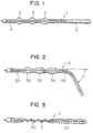
- Fig. 1 shows the distal end of an elongated wire 1 for opening an obstructive or stenosed region of a coronary artery, a wire body 2, projections 3 formed on the wire body 2, and a core 4 embedded in the wire body 2.
- the wire body 2 is made of a material (flexible material) which is deformed by an external force, and is not restored to its original configuration by itself, or a material (resilient or elastic material) which, after having been deformed, is restored to its original configuration, at the time of the use of the wire 1 for opening the stenosed region of a coronary artery (at the time of insertion into an artery).
- the wire body 2 is made of a plastic material such as enamel, Teflon (trade name) or the like.
- the wire body may have a coating layer such as hydrophilic polymer or the like, on the distal end portion of the wire body.
- the wire body may have a coating layer such as tungsten-mixed polyurethane elastomer or the like, on a portion of the wire body except for the distal end portion thereof.
- the wire body 2 is circular in transverse cross-section, and has a diameter such as 0.5 to 1.2 mm. The wire body 2 has a distal end which is so rounded as not to injure the coronary artery or the like.
- Each of the projections 3 is formed substantially into a spherical shape. In the illustrated embodiment, three projections are provided. However, the number of the projections is optional.
- the outer diameter of each projection 3 is about 0.1 to 2.0 mm larger than the diameter of the wire body 2.
- the interval or spacing between the adjacent projections 3 is e.g. 0.5 to 5.5 mm.
- Each projection 3 has an entire length of 5 to 40 mm.
- the spacing between the projection 3 adjacent to the distal end of the wire body 2 and the distal end thereof is e.g. 10 to 50 mm, preferably, 10 to 20 mm.
- the core 4 is made of a material (elastic material) which is restored to its original configuration after having been subjected to an external force and been deformed.
- a material for example, it is made of stainless steel, an alloy (nickel - titanium alloy or the like), a piano wire material, an amorphous metal, gold, a plastic material, or the like.
- the core 4 has the function of reinforcing the wire body 2, or the function of increasing the elasticity of the wire body 2.
- the core 4 does not reach the distal end of the wire body 2, but terminates at a location between the distal end and the projection 3.
- the core 4 has a diameter such as 0.1 to 1 mm.
- Fig. 2 shows a wire 1A which has a plurality of projections 3A each of which is formed into a circular cylinder shape.
- a portion of the wire 1A between the distal end thereof and the projection 3A is bent through an angle ⁇ .
- a wire body 2A is made of a material (flexible material) which is deformed by on external force, and is not restored to its original configuration by itself, or a material (resilient or elastic material) which, after having been deformed, is restored to its original configuration, at the time of the use of the wire 1A for opening the stenosed region of a coronary artery.
- a core 4A is made of a material (elastic material) which, after having been subjected to an external force, is deformed, and thereafter restored to its original configuration, at the use of the wire 1A for opening the stenosed region of a coronary artery. Further, it is convenient if the core 4A is made of a material which, when an operator applies an external force larger than the elastic limit to the material, can plastically be deformed into an appropriate angle ⁇ (the angle ⁇ is an optional angle equal to or less than 90°), or can be deformed into an appropriate configuration. The reason is as follows.
- the operator can deform the portion of the distal end of the wire 1A for opening the stenosed region of the coronary artery, in accordance with parts of the stenosed region.
- the core 4A reaches a location adjacent to the distal end of the wire body 2A.
- Fig. 3 illustrates a wire 1C which is arranged such that a spiral element 5 instead of the projections is provided in concentric relation to a core 4C, and a portion of the wire body 2C, which is within a range of the spiral element 5, is resected.
- the spiral element 5 is made of metal wire (the spiral element may be the core) having an affinity to the human body, a metal wire having high resistance to electricity, a metal wire having high or strong magnetism, or a plastic wire.
- the spiral element 5 has an outer diameter which may be larger than that of the wire body 2C, or may be smaller than the latter.
- a blank wire of the spiral element 5 has a diameter of 0.1 to 1 mm, and a pitch of 0.5 to 5 mm.
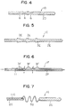
- Fig. 4 illustrates a wire 1D which is arranged such that the wire body 2D is made of a resilient or elastic material, and the wire 1D is provided with a plurality of ring-like grooves 6 in substitution for the projections or projection.
- Fig. 5 illustrates a wire 1E which is arranged such that each of a plurality of projections 3E is in the form of a circular truncated cone. Also in this case, the wire body 2E is made of a resilient or elastic material, similarly to the embodiment shown in Fig. 4.
- Fig. 6 illustrates a wire 1F, a plurality of projections 3F being arranged only on one side of the wire body 2F, and a passage 11 through which a drug (a vascodilation drug, a thrombolytic drug or the like) is supplied, is formed in the wire body 2F.
- the passage 11 opens to the wire surface within the range of the projections 3F and at the distal end of the wire.
- the flow direction of the drug is indicated by arrows.
- Fig. 7 illustrates a wire 1G which is provided with a spiral element 5G, similar to the embodiment shown in Fig. 4.
- the wire 1G is not provided with a core, but is formed with a passage 11G.
- the passage 11G opens to the surface of the wire body 2G at a location in short of the spiral element 5G.
- the arrangement can be such that a glass fiber is inserted through the passage, and a laser beam is capable of being applied from outside.
- a method of opening an obstructive or stenosed region of a coronary artery, by the use of the brushing wire 1 for opening the coronary revascularization, will next be described with reference to Figs. 8 and 9.
- the revascularization is effected in the following order:
- the projections 3 on the wire 1 for coronary revascularization are located at the stenosed region and are reciprocated, whereby it is possible to cut and remove a thrombus, a hypertrophied vascular endothelium, cholesterol and the like existing in the stenosed region, to reopen blood stream to the heart or the like. Further, application of high frequency current through the core, and application of a high frequency magnetic field through the core enable the above-described thrombus and the like to be cauterized and removed.
- the conventional balloon catheter is confined merely to enlarge such hypertrophied sections without removing the same. Accordingly, as time elapses, there is a very high probability that the lumen is depressed to cause restenosis.
- the wire 1 for coronary revascularization according to the invention, since the hypertrophied sections within the artery are removed, the probability that restenosis occurs becomes very low.
- the use of wires of various sizes it is possible to reopen a stenosed region of a coronary artery to enlarge the inner diameter of the coronary artery stepwise. Since the distal end of the wire is very rich in elasticity, a complication such as injury to a coronary artery, cardiogenic shock or the like is difficult to occur so that the wire exhibits effectiveness in any coronary arteries having a small diameter.
- the elastic portion between the distal end of the wire and the projections 3 serves as a guide, it is possible to easily insert the wire into the stenosed region of a coronary artery. Furthermore, since slippage of the surface of the wire body 2 is superior, there is no case the inner wall of the coronary artery injured. Moreover, as described above, since it is sufficient only that the wire 1 is inserted into the coronary artery and is reciprocated, operating manipulation or handling is simple and easy. Further, since the structure or construction of the wire 1 is simple, the manufacturing cost therefor is low.
- the wires 1, 1B or 1C do not necessarily require a core.
- the core may reach the distal end of the wire body, or may reach a location slightly in short of the distal end of the wire body.
- the wires 1, 1A, 1C and 1D it is possible to provide a passage 11 or 11G.
- the arrangement may be such that the core and the passage are provided in the wire body in parallel relation to each other, and the passage larger than the core is formed so that the core is arranged within the passage.
- the opening location of each of the passages 11 and 11G can be anywhere within the range of the distal end of the wire, and the number of the openings (outlets) is optional.
- the projections 3, 3A, 3E and 3F and the grooves 6 into any various configurations or shapes, and both the projections and the grooves can be provided.
- the number of the projections and the grooves is optional, and the arranging locations thereof can be anywhere if the arranging locations are within the range of the distal end of the wire.
- the wire for coronary revascularization has a very low probability that restenosis after operation occurs, and a complication such as a myocardial infarction, cardiogenic shock, coronary-artery injury or the like is difficult to occur. Moreover, the tendency of hemorrhage is low, and the percentage of success is very high. Further, there are the advantages that the manufacturing cost is low, and operating manipulation or handling is simple and easy.
Abstract
Claims (10)
- Dispositif destiné à la revascularisation coronaire et, en particulier, à ouvrir ou élargir des vaisseaux sanguins tels que des régions obstruées ou sténosées dans des artères coronaires pour laisser passer un grand débit sanguin, comprenant un cathéter (7) destiné à être inséré dans une artère coronaire et un fil (1) logé dans le cathéter (7) et qui possède, pour élargir et par conséquent ouvrir la région vasculaire sténosée, des saillies (3) ou gorges (6) formées dans la région de l'extrémité distale du corps (2) du fil flexible ou élastique, le fil (1) ayant une partie de guidage à son extrémité distale, ladite partie de guidage étant circulaire en section transversale et ne possédant pas de saillies ni de gorges,
caractérisé en ce que
le fil (1) possède une pluralité de saillies sphériques (3) ou de gorges annulaires (6), les saillies (3) ou gorges (6) étant isolées ou séparées les unes des autres, et en ce que la partie de guidage du corps (2) du fil a une longueur de 10 à 50 mm à partir de son extrémité distale. - Dispositif destiné à la revascularisation coronaire et, en particulier, à ouvrir ou élargir des vaisseaux sanguins tels que des régions obstruées ou sténosées dans des artères coronaires pour laisser passer un grand débit sanguin, comprenant un cathéter (7) destiné à être inséré dans une artère coronaire et un fil (1) logé dans le cathéter (7) et qui possède, pour élargir et par conséquent ouvrir la région vasculaire sténosée, un élément hélicoïdal (5) prévu à distance de l'extrémité distale du corps (2) du fil flexible ou élastique, de manière à former à l'extrémité distale du corps du fil une partie de guidage, circulaire en section transversale et démunie d'élément hélicoïdal,
caractérisé en ce que
une partie du corps (2) du fil comprise dans la région de l'élément hélicoïdal (5) est enlevée et en ce que la partie de guidage du corps (2) du fil a une longueur de 10 à 50 mm à partir de son extrémité distale extrême. - Dispositif selon la revendication 1, caractérisé en ce que chaque saillie sphérique (3) est faite d'une matière choisie dans le groupe constitué par une matière plastique, une matière à haute résistivité électrique et une matière fortement magnétique.
- Dispositif selon la revendication 2, caractérisé en ce que l'élément hélicoïdal (5) est fait d'une matière choisie dans le groupe constitué par une matière à haute résistivité électrique et une matière fortement magnétique.
- Dispositif selon une quelconque des revendications 1 à 4, caractérisé en ce que l'âme élastique (4) est noyée dans le corps (2) du fil.
- Dispositif selon une quelconque des revendications 1 à 5, caractérisé en ce que le corps (2) du fil est coudé en un emplacement entre l'extrémité distale du corps du fil et les saillies sphériques (3), les gorges annulaires (6) ou l'élément hélicoïdal (5).
- Dispositif selon une quelconque des revendications 1 à 4, caractérisé en ce qu'un passage (11) servant à acheminer un médicament est formé dans le corps (2) du fil et débouche à la surface du corps du fil dans la région de l'extrémité distale du corps du fil.
- Dispositif selon une quelconque des revendications 1 à 6, caractérisé en ce qu'il est prévu un passage (11) formé dans le corps (2) du fil et dans lequel est insérée une fibre de verre, et en ce qu'un rayon laser peut être appliqué à travers la fibre de verre.
- Dispositif selon une quelconque des revendications 2 ou 4 à 8, caractérisé en ce qu'une âme (4C) est prévue dans le corps (2) du fil flexible ou élastique, en ce que l'élément hélicoïdal (5) fait d'une matière à haute résistivité électrique et agencé à distance de l'extrémité distale du corps du fil est relié à ladite âme, et en ce qu'un courant à haute fréquence est appliqué à l'élément hélicoïdal de manière à pouvoir le chauffer.
- Dispositif selon une quelconque des revendications 1 à 9, caractérisé en ce que l'extrémité distale du corps (2) du fil flexible ou élastique est faite d'une matière fortement magnétique et peut être chauffée par un champ magnétique à haute fréquence.
Applications Claiming Priority (3)
| Application Number | Priority Date | Filing Date | Title |
|---|---|---|---|
| JP4865790 | 1990-02-28 | ||
| JP48657/90 | 1990-02-28 | ||
| PCT/JP1991/000272 WO1991012770A1 (fr) | 1990-02-28 | 1991-02-28 | Fil destine a ouvrir une partie obstruee de vaisseau sanguin |
Publications (3)
| Publication Number | Publication Date |
|---|---|
| EP0473790A1 EP0473790A1 (fr) | 1992-03-11 |
| EP0473790A4 EP0473790A4 (en) | 1992-08-12 |
| EP0473790B1 true EP0473790B1 (fr) | 1996-05-15 |
Family
ID=12809421
Family Applications (1)
| Application Number | Title | Priority Date | Filing Date |
|---|---|---|---|
| EP91904799A Expired - Lifetime EP0473790B1 (fr) | 1990-02-28 | 1991-02-28 | Fil destine a ouvrir une partie obstruee de vaisseau sanguin |
Country Status (5)
| Country | Link |
|---|---|
| EP (1) | EP0473790B1 (fr) |
| AU (1) | AU655920B2 (fr) |
| CA (1) | CA2053853A1 (fr) |
| DE (1) | DE69119515T2 (fr) |
| WO (1) | WO1991012770A1 (fr) |
Cited By (1)
| Publication number | Priority date | Publication date | Assignee | Title |
|---|---|---|---|---|
| US8608754B2 (en) | 1996-02-02 | 2013-12-17 | The Regents Of The University Of California | Clot capture coil |
Families Citing this family (9)
| Publication number | Priority date | Publication date | Assignee | Title |
|---|---|---|---|---|
| US5129910A (en) * | 1991-07-26 | 1992-07-14 | The Regents Of The University Of California | Stone expulsion stent |
| US5370653A (en) * | 1993-07-22 | 1994-12-06 | Micro Therapeutics, Inc. | Thrombectomy method and apparatus |
| DE60138360D1 (de) * | 2000-01-04 | 2009-05-28 | Medtronic Vascular Inc | Vorrichtung zur einstellung eines kanals zwischen angrenzenden körperlumen |
| JP4138582B2 (ja) | 2002-08-23 | 2008-08-27 | テルモ株式会社 | ガイドワイヤ |
| US8052694B2 (en) * | 2003-03-19 | 2011-11-08 | Boston Scientific Scimed, Inc. | Device for manipulating material in a tissue |
| CN100558423C (zh) | 2003-12-18 | 2009-11-11 | 泰尔茂株式会社 | 导向线 |
| JP5139184B2 (ja) * | 2008-07-16 | 2013-02-06 | オリンパス株式会社 | 医療用器具の製造方法および医療用器具 |
| DE102012106626B3 (de) | 2012-07-20 | 2013-09-26 | Krauss-Maffei Wegmann Gmbh & Co. Kg | Waffenplattform, militärisches Fahrzeug mit einer Waffenplattform und Verfahren zum Betrieb einer Waffenplattform |
| JP6883986B2 (ja) * | 2013-11-18 | 2021-06-09 | コーニンクレッカ フィリップス エヌ ヴェKoninklijke Philips N.V. | 治療用エネルギ送達を含む治療カテーテル |
Citations (1)
| Publication number | Priority date | Publication date | Assignee | Title |
|---|---|---|---|---|
| JPH0675064A (ja) * | 1990-12-11 | 1994-03-18 | Sounds Fun Inc | 動物時計 |
Family Cites Families (15)
| Publication number | Priority date | Publication date | Assignee | Title |
|---|---|---|---|---|
| US2756752A (en) * | 1953-12-23 | 1956-07-31 | Scherlis Irving | Surgical instrument |
| US3635223A (en) * | 1969-12-02 | 1972-01-18 | Us Catheter & Instr Corp | Embolectomy catheter |
| US4030503A (en) * | 1975-11-05 | 1977-06-21 | Clark Iii William T | Embolectomy catheter |
| JPS52141092A (en) * | 1976-05-20 | 1977-11-25 | Nippon Zeon Co | Blood bessel catheter |
| CA1124155A (fr) * | 1979-08-16 | 1982-05-25 | Robert C. White | Instrument pour effectuer une endarteriectomie |
| US4548206A (en) * | 1983-07-21 | 1985-10-22 | Cook, Incorporated | Catheter wire guide with movable mandril |
| CA1266412A (fr) * | 1984-10-24 | 1990-03-06 | J. Richard Spears | Methode et appareil pour effectuer des angioplasties |
| US4654024A (en) * | 1985-09-04 | 1987-03-31 | C.R. Bard, Inc. | Thermorecanalization catheter and method for use |
| DE3533452A1 (de) * | 1985-09-19 | 1987-03-26 | Messerschmitt Boelkow Blohm | Fuehrungssonde |
| CA1293663C (fr) * | 1986-01-06 | 1991-12-31 | David Christopher Auth | Appareil de micro-dissection intravasculaire |
| AU607692B2 (en) * | 1986-01-06 | 1991-03-14 | Boston Scientific Corporation Northwest Technology Center, Inc. | Transluminal microdissection device |
| JPH0243397Y2 (fr) * | 1986-03-27 | 1990-11-19 | ||
| JPS62231675A (ja) * | 1986-03-31 | 1987-10-12 | 加藤発条株式会社 | 医療用ガイドワイヤ |
| DE8714529U1 (fr) * | 1987-10-31 | 1988-12-08 | Schnepp-Pesch, Wolfram, 7505 Ettlingen, De | |
| EP0415997A4 (en) * | 1988-05-18 | 1992-04-08 | Kasevich Associates, Inc. | Microwave balloon angioplasty |
-
1991
- 1991-02-28 AU AU73308/91A patent/AU655920B2/en not_active Ceased
- 1991-02-28 DE DE69119515T patent/DE69119515T2/de not_active Expired - Fee Related
- 1991-02-28 EP EP91904799A patent/EP0473790B1/fr not_active Expired - Lifetime
- 1991-02-28 CA CA002053853A patent/CA2053853A1/fr not_active Abandoned
- 1991-02-28 WO PCT/JP1991/000272 patent/WO1991012770A1/fr active IP Right Grant
Patent Citations (1)
| Publication number | Priority date | Publication date | Assignee | Title |
|---|---|---|---|---|
| JPH0675064A (ja) * | 1990-12-11 | 1994-03-18 | Sounds Fun Inc | 動物時計 |
Cited By (1)
| Publication number | Priority date | Publication date | Assignee | Title |
|---|---|---|---|---|
| US8608754B2 (en) | 1996-02-02 | 2013-12-17 | The Regents Of The University Of California | Clot capture coil |
Also Published As
| Publication number | Publication date |
|---|---|
| WO1991012770A1 (fr) | 1991-09-05 |
| EP0473790A1 (fr) | 1992-03-11 |
| AU655920B2 (en) | 1995-01-19 |
| DE69119515T2 (de) | 1996-11-21 |
| DE69119515D1 (de) | 1996-06-20 |
| EP0473790A4 (en) | 1992-08-12 |
| AU7330891A (en) | 1991-09-18 |
| CA2053853A1 (fr) | 1991-08-29 |
Similar Documents
| Publication | Publication Date | Title |
|---|---|---|
| US8968350B2 (en) | Total occlusion guidewire device | |
| EP2482913B1 (fr) | Ensemble ballonnet de coupe et son procédé de fabrication | |
| EP1092449A1 (fr) | Catheter a fil-guide | |
| AU2002248543A1 (en) | Total occlusion guidewire device | |
| US20050101836A1 (en) | Medical guide wire | |
| JPH06502333A (ja) | 仮ステント及びその使用法と製造方法 | |
| WO1987004935A1 (fr) | Distendeur intravasculaire et systeme d'introduction percutanee | |
| JP2005500079A (ja) | 交換可能バルーンを有するカテーテル | |
| JPH0653125B2 (ja) | 括約筋切開法ならびに制御された曲げおよび向きを備えた器具 | |
| JP5153767B2 (ja) | ガイドワイヤ配置装置 | |
| US6485458B1 (en) | Surgical insertion instrument body having a distending portion | |
| EP0473790B1 (fr) | Fil destine a ouvrir une partie obstruee de vaisseau sanguin | |
| JP2022518108A (ja) | ガイド延長カテーテル | |
| JP2644921B2 (ja) | 血管閉塞部開通用ワイヤ | |
| JPH06197899A (ja) | 細胞診用細胞採取または血管内閉塞部位貫通医療処置器具 | |
| JP4188431B2 (ja) | ステント | |
| JP3815828B2 (ja) | 管状器官の治療具 | |
| WO2023286637A1 (fr) | Dispositif de chauffage, système de chauffage, et procédé de fonctionnement du dispositif de chauffage de veine | |
| JPS63262160A (ja) | カテ−テル | |
| JP5618421B2 (ja) | バルーンカテーテル | |
| JP4954571B2 (ja) | 長尺状医療用具保持システムおよびその方法 | |
| JPS6118464B2 (fr) |
Legal Events
| Date | Code | Title | Description |
|---|---|---|---|
| PUAI | Public reference made under article 153(3) epc to a published international application that has entered the european phase |
Free format text: ORIGINAL CODE: 0009012 |
|
| AK | Designated contracting states |
Kind code of ref document: A1 Designated state(s): BE CH DE DK FR GB IT LI NL |
|
| 17P | Request for examination filed |
Effective date: 19920226 |
|
| A4 | Supplementary search report drawn up and despatched |
Effective date: 19920619 |
|
| AK | Designated contracting states |
Kind code of ref document: A4 Designated state(s): BE CH DE DK FR GB IT LI NL |
|
| 17Q | First examination report despatched |
Effective date: 19930924 |
|
| GRAH | Despatch of communication of intention to grant a patent |
Free format text: ORIGINAL CODE: EPIDOS IGRA |
|
| GRAA | (expected) grant |
Free format text: ORIGINAL CODE: 0009210 |
|
| AK | Designated contracting states |
Kind code of ref document: B1 Designated state(s): DE FR GB |
|
| REF | Corresponds to: |
Ref document number: 69119515 Country of ref document: DE Date of ref document: 19960620 |
|
| ET | Fr: translation filed | ||
| PLBE | No opposition filed within time limit |
Free format text: ORIGINAL CODE: 0009261 |
|
| STAA | Information on the status of an ep patent application or granted ep patent |
Free format text: STATUS: NO OPPOSITION FILED WITHIN TIME LIMIT |
|
| 26N | No opposition filed | ||
| PGFP | Annual fee paid to national office [announced via postgrant information from national office to epo] |
Ref country code: GB Payment date: 19980128 Year of fee payment: 8 |
|
| PGFP | Annual fee paid to national office [announced via postgrant information from national office to epo] |
Ref country code: FR Payment date: 19980219 Year of fee payment: 8 |
|
| PGFP | Annual fee paid to national office [announced via postgrant information from national office to epo] |
Ref country code: DE Payment date: 19980406 Year of fee payment: 8 |
|
| PG25 | Lapsed in a contracting state [announced via postgrant information from national office to epo] |
Ref country code: GB Free format text: LAPSE BECAUSE OF NON-PAYMENT OF DUE FEES Effective date: 19990228 |
|
| GBPC | Gb: european patent ceased through non-payment of renewal fee |
Effective date: 19990228 |
|
| PG25 | Lapsed in a contracting state [announced via postgrant information from national office to epo] |
Ref country code: FR Free format text: LAPSE BECAUSE OF NON-PAYMENT OF DUE FEES Effective date: 19991029 |
|
| PG25 | Lapsed in a contracting state [announced via postgrant information from national office to epo] |
Ref country code: DE Free format text: LAPSE BECAUSE OF NON-PAYMENT OF DUE FEES Effective date: 19991201 |
|
| REG | Reference to a national code |
Ref country code: FR Ref legal event code: ST |