EP0473046A2 - Mehrpoliger Steckverbinder mit gebogenen Kontaktfüssen - Google Patents
Mehrpoliger Steckverbinder mit gebogenen Kontaktfüssen Download PDFInfo
- Publication number
- EP0473046A2 EP0473046A2 EP91113936A EP91113936A EP0473046A2 EP 0473046 A2 EP0473046 A2 EP 0473046A2 EP 91113936 A EP91113936 A EP 91113936A EP 91113936 A EP91113936 A EP 91113936A EP 0473046 A2 EP0473046 A2 EP 0473046A2
- Authority
- EP
- European Patent Office
- Prior art keywords
- connector
- plug
- legs
- connector legs
- multipole
- Prior art date
- Legal status (The legal status is an assumption and is not a legal conclusion. Google has not performed a legal analysis and makes no representation as to the accuracy of the status listed.)
- Granted
Links
- 230000005405 multipole Effects 0.000 title claims abstract description 18
- 238000005452 bending Methods 0.000 abstract description 2
- 230000004075 alteration Effects 0.000 description 1
- 230000008878 coupling Effects 0.000 description 1
- 238000010168 coupling process Methods 0.000 description 1
- 238000005859 coupling reaction Methods 0.000 description 1
Images
Classifications
-
- H—ELECTRICITY
- H01—ELECTRIC ELEMENTS
- H01R—ELECTRICALLY-CONDUCTIVE CONNECTIONS; STRUCTURAL ASSOCIATIONS OF A PLURALITY OF MUTUALLY-INSULATED ELECTRICAL CONNECTING ELEMENTS; COUPLING DEVICES; CURRENT COLLECTORS
- H01R12/00—Structural associations of a plurality of mutually-insulated electrical connecting elements, specially adapted for printed circuits, e.g. printed circuit boards [PCB], flat or ribbon cables, or like generally planar structures, e.g. terminal strips, terminal blocks; Coupling devices specially adapted for printed circuits, flat or ribbon cables, or like generally planar structures; Terminals specially adapted for contact with, or insertion into, printed circuits, flat or ribbon cables, or like generally planar structures
- H01R12/70—Coupling devices
- H01R12/71—Coupling devices for rigid printing circuits or like structures
- H01R12/72—Coupling devices for rigid printing circuits or like structures coupling with the edge of the rigid printed circuits or like structures
- H01R12/722—Coupling devices for rigid printing circuits or like structures coupling with the edge of the rigid printed circuits or like structures coupling devices mounted on the edge of the printed circuits
- H01R12/724—Coupling devices for rigid printing circuits or like structures coupling with the edge of the rigid printed circuits or like structures coupling devices mounted on the edge of the printed circuits containing contact members forming a right angle
Definitions
- the invention relates to a multipole plug-in connector for the plugable connection of a multipole, planar connection region of a circuit board or the like which is equipped with individual connections arranged in matrix-like distribution at a given grid spacing, in which connector a plug part to be connected to the multipole connection region is provided with a plurality of mutually offset rows of connector legs, bent approximately at right angles, of the individual contacts held in the plug part.
- Multipole plug-in connectors preferably for a connection region of a circuit board running along one edge, in which the contacts in the housing of the plug-in connector are arranged running in a plurality of rows parallel one above the other and substantially parallel to the circuit board, are known.
- Owing to the advancing and retracting direction parallel to the circuit board for the removable plug part it is necessary to provide the plug part fixed to the circuit board with bent connector legs on the rear side, i.e. on the side facing the connection region of the circuit board. Since the connector legs have to be matched to the grid spacing of the contact holes in the connection region of the circuit board, it is unavoidable that the connector legs of the various rows of contacts arranged one above or next to the other of the plug part fixed to the circuit board are of varying length.
- the arrangement is generally such that the row of contacts lying closest to the connection region of the circuit board is provided with the shortest bent connector legs and the rows of contacts lying above are provided with respectively overreaching, longer connector legs.
- the invention is consequently based on the object of improving a multipole plug-in connector of said type having bent connector legs in such a way that equally long signal delay times can be ensured for the individual contacts.
- the technical object presented is achieved for a multipole plug-in connector of the generic type mentioned at the beginning by a special manner of bending the connector legs, which ensures that the respective overall geometrical length of the individual connector legs is approximately equal for all the contacts.
- the way in which this is achieved according to the invention is that the length of the limbs close to the plug of the row of connector legs furthest away from the connection region on the circuit board is the shortest and the length of the bent limbs of these connector legs is the longest, whereas the limbs close to the plug part of the lowermost row of connector legs, lying closest to the circuit board, are the longest and the bent limbs of these connector legs, leading to the contact region on the circuit board, are the shortest, avoidance of a contact-making overlap of the higher-lying rows of connector legs with the rows of connector legs underneath being accomplished by a lateral angling-off of the individual connector legs.
- the length of the limbs close to the plug of the connector legs of the row remote from the circuit board and the row close to the circuit board, as well as any further rows of contacts lying in between is chosen approximately in inverse ratio to the length of the limbs of the respective connector legs bent toward the respective connection region on the circuit board, based on the grid spacing of the contact holes on the circuit board on the one hand and based on the corresponding grid spacing of the individual contacts of the multipole plug-in connector on the other hand, approximately equal lengths of all the connector legs are inevitably obtained.
- the arrangement of the various rows of connector legs is thus precisely the inverse of that in the hitherto known prior art, in which the rows of connector legs closest to the circuit board were always led onto the row of contact holes on the circuit board closest to the plug housing, whereas conversely the rows of connector legs most remote from the circuit board were intended to reach over all the other circuit board rows for contacting the row of contact holes on the circuit board most remote from the plug housing and accordingly had to be of a greater geometrical length.
- the particular advantage of the invention is that, with a completely unchanged grid spacing both of the contact arrangement in the plug housing and of the contact holes of the connection region, for example of a circuit board, virtually exactly equally long connector legs and consequently equal signal delay times have been achieved for all the contacts.
- the entire connecting panel (hole panel) on the circuit board is simply shifted by preferably 1/2 of a grid parallel to the edge of the circuit board.
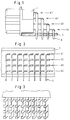
- the uppermost, first row A1 of the contact legs is led onto the row of contact holes lying closest to the plug part 1 in the connection region of the circuit board 2.
- the second row A2 of the contact legs is led onto a next row of contact holes of the connection region of the circuit board, spaced somewhat further away from the plug part 1, and so on in such a way that finally the lowermost row A4 of the contact legs is connected to a row of contact holes which is furthest away from the plug part 1.
- the limb close to the plug part of the row of contact legs A1 is in each case the shortest and the bent limb, leading to the contact region on the circuit board, of the row A1 is in each case the longest.
- the limb respectively leading away from the plug part 1 is the longest
- the bent limb, leading towards the circuit board 2 is the shortest.
- the length of the limbs close to the plug of the connector legs of the first, second, third and fourth rows A1, A2, A3 and A4, respectively is chosen approximately in inverse ratio to the length of the limbs of the respective connector legs bent toward the connection region.
- the connector legs of the individual rows are laterally bent or angled-off, so that a contact-making in the region of the limbs close to the plug of the respectively lower rows of the connector legs is avoided.
Landscapes
- Coupling Device And Connection With Printed Circuit (AREA)
Applications Claiming Priority (2)
| Application Number | Priority Date | Filing Date | Title |
|---|---|---|---|
| DE4027509A DE4027509C2 (de) | 1990-08-30 | 1990-08-30 | Vielpoliger Steckverbinder mit abgewinkelten Anschlußbeinen |
| DE4027509 | 1990-08-30 |
Publications (3)
| Publication Number | Publication Date |
|---|---|
| EP0473046A2 true EP0473046A2 (de) | 1992-03-04 |
| EP0473046A3 EP0473046A3 (en) | 1992-09-16 |
| EP0473046B1 EP0473046B1 (de) | 1996-04-10 |
Family
ID=6413269
Family Applications (1)
| Application Number | Title | Priority Date | Filing Date |
|---|---|---|---|
| EP91113936A Expired - Lifetime EP0473046B1 (de) | 1990-08-30 | 1991-08-20 | Mehrpoliger Steckverbinder mit gebogenen Kontaktfüssen |
Country Status (4)
| Country | Link |
|---|---|
| US (1) | US5173056A (de) |
| EP (1) | EP0473046B1 (de) |
| DE (1) | DE4027509C2 (de) |
| SG (1) | SG85574A1 (de) |
Cited By (2)
| Publication number | Priority date | Publication date | Assignee | Title |
|---|---|---|---|---|
| DE10301278A1 (de) * | 2003-01-15 | 2004-07-29 | Siemens Ag | Vorrichtung zur Verbindung von Leitern von Datenkabeln sowie Kabelmuffe mit einer derartigen Vorrichtung |
| WO2017106169A3 (en) * | 2015-12-15 | 2017-08-24 | Panduit Corp. | Field terminable rj45 plug assembly |
Families Citing this family (13)
| Publication number | Priority date | Publication date | Assignee | Title |
|---|---|---|---|---|
| US5201662A (en) * | 1991-08-23 | 1993-04-13 | Molex Incorporated | Electrical connector for mounting on a printed circuit board |
| JP2575617Y2 (ja) * | 1993-01-14 | 1998-07-02 | 矢崎総業株式会社 | 回路基板用コネクタ |
| JP2623435B2 (ja) * | 1993-09-17 | 1997-06-25 | 日本航空電子工業株式会社 | 等長ライトアングルコネクタ |
| US5516297A (en) * | 1993-09-28 | 1996-05-14 | Kel Corporation | Surface mount electrical devices |
| US5591035A (en) * | 1994-10-06 | 1997-01-07 | The Whitaker Corporation | Electrical connector with shortened contact |
| DE19541476A1 (de) * | 1995-11-07 | 1997-06-19 | Siemens Ag | Kontaktanordnung für eine Leiterplattensteckbuchse |
| US6066815A (en) * | 1998-08-24 | 2000-05-23 | Illinois Tool Works Inc. | Electrical connector-power switch module |
| US6491545B1 (en) | 2000-05-05 | 2002-12-10 | Molex Incorporated | Modular shielded coaxial cable connector |
| US6492603B1 (en) | 2001-08-14 | 2002-12-10 | Illinois Tool Works Inc. | Power switch module |
| US6729891B2 (en) * | 2002-06-06 | 2004-05-04 | International Business Machines Corporation | Right angle board-to-board connector with balanced impedance |
| US20040242062A1 (en) * | 2003-06-02 | 2004-12-02 | Hughes Karin R. | Methods and apparatus for managing cables and cable connectors |
| US8715004B2 (en) | 2010-07-27 | 2014-05-06 | Fci Americas Technology Llc | Backplane connector with reduced circuit board overhang |
| DE102011089020B4 (de) * | 2011-12-19 | 2023-11-16 | Zf Friedrichshafen Ag | Kontaktverbinder und Verfahren zur Herstellung eines Kontaktverbinders |
Citations (2)
| Publication number | Priority date | Publication date | Assignee | Title |
|---|---|---|---|---|
| US3493916A (en) * | 1967-07-24 | 1970-02-03 | Molex Products Co | Printed circuit board terminal and connector |
| US4898546A (en) * | 1988-12-16 | 1990-02-06 | E. I. Du Pont De Nemours And Company | Ground plane shield device for right angle connectors |
Family Cites Families (3)
| Publication number | Priority date | Publication date | Assignee | Title |
|---|---|---|---|---|
| US3384864A (en) * | 1965-11-15 | 1968-05-21 | Sperry Rand Corp | Electrical connector assembly |
| DE3032585A1 (de) * | 1980-08-29 | 1982-05-13 | Bunker Ramo Corp., 60521 Oak Brook, Ill. | Elektrischer steckverbinder fuer flachkabel |
| DE8107135U1 (de) * | 1981-03-12 | 1981-08-06 | Siemens AG, 1000 Berlin und 8000 München | Bandkabel-Anschlußvorrichtung |
-
1990
- 1990-08-30 DE DE4027509A patent/DE4027509C2/de not_active Expired - Fee Related
-
1991
- 1991-08-20 EP EP91113936A patent/EP0473046B1/de not_active Expired - Lifetime
- 1991-08-20 SG SG9604063A patent/SG85574A1/en unknown
- 1991-08-29 US US07/751,496 patent/US5173056A/en not_active Expired - Fee Related
Patent Citations (2)
| Publication number | Priority date | Publication date | Assignee | Title |
|---|---|---|---|---|
| US3493916A (en) * | 1967-07-24 | 1970-02-03 | Molex Products Co | Printed circuit board terminal and connector |
| US4898546A (en) * | 1988-12-16 | 1990-02-06 | E. I. Du Pont De Nemours And Company | Ground plane shield device for right angle connectors |
Cited By (5)
| Publication number | Priority date | Publication date | Assignee | Title |
|---|---|---|---|---|
| DE10301278A1 (de) * | 2003-01-15 | 2004-07-29 | Siemens Ag | Vorrichtung zur Verbindung von Leitern von Datenkabeln sowie Kabelmuffe mit einer derartigen Vorrichtung |
| DE10301278B4 (de) * | 2003-01-15 | 2005-05-19 | Siemens Ag | Vorrichtung zur Verbindung von Leitern von Datenkabeln sowie Kabelmuffe mit einer derartigen Vorrichtung |
| WO2017106169A3 (en) * | 2015-12-15 | 2017-08-24 | Panduit Corp. | Field terminable rj45 plug assembly |
| CN108370119A (zh) * | 2015-12-15 | 2018-08-03 | 泛达公司 | 可现场端接rj45插头组件 |
| US11677198B2 (en) | 2015-12-15 | 2023-06-13 | Panduit Corp. | Field terminable RJ45 plug assembly |
Also Published As
| Publication number | Publication date |
|---|---|
| DE4027509A1 (de) | 1992-03-05 |
| SG85574A1 (en) | 2002-01-15 |
| EP0473046A3 (en) | 1992-09-16 |
| US5173056A (en) | 1992-12-22 |
| DE4027509C2 (de) | 1996-12-19 |
| EP0473046B1 (de) | 1996-04-10 |
Similar Documents
| Publication | Publication Date | Title |
|---|---|---|
| EP0473046B1 (de) | Mehrpoliger Steckverbinder mit gebogenen Kontaktfüssen | |
| US5893761A (en) | Printed circuit board connector | |
| EP0757851B1 (de) | Leitende hülle für elektrische verbinder | |
| US5904594A (en) | Electrical connector with shielding | |
| US5224867A (en) | Electrical connector for coaxial flat cable | |
| US4940431A (en) | Series terminal for two-wire power supply to electrical or electronic components, especially initiators | |
| US6764315B2 (en) | Electrical connector | |
| EP0002890B1 (de) | Abgeschirmter elektrischer Verbinder | |
| SE466126B (sv) | Flerpoligt skaermat kontaktdon med gemensam jord | |
| US8128433B2 (en) | Modular jack having a cross talk compensation circuit and robust receptacle terminals | |
| EP0620616A1 (de) | Verbinder für koaxiales und/oder zweiadriges Kabel | |
| US6270358B1 (en) | Low-voltage male connector | |
| US9401558B1 (en) | Power connector | |
| EP0422807A2 (de) | Leiterplattensteckverbinder | |
| AU7736691A (en) | Connectors with ground structure | |
| EP1427061A3 (de) | Elektrischer Verbinder für Differenz-Signale | |
| CN103548215B (zh) | 电连接器组件、与其配合的工具以及组装连接器的方法 | |
| US8684770B2 (en) | Cable end connector and cable connector assembly having the same | |
| ATE415002T1 (de) | Schneller, dichter elektrischer verbinder | |
| CA2085270A1 (en) | High frequency electrical connector | |
| JPH0636382B2 (ja) | 電気コネクター | |
| CN101351932B (zh) | 差分传输连接器和与其嵌合的基板安装用差分传输连接器 | |
| EP0395609B1 (de) | Oberflächenverbinder für Radiofrequenzsignale | |
| US10925159B2 (en) | Circuit device | |
| TW200841540A (en) | Electrical plug-in connector |
Legal Events
| Date | Code | Title | Description |
|---|---|---|---|
| PUAI | Public reference made under article 153(3) epc to a published international application that has entered the european phase |
Free format text: ORIGINAL CODE: 0009012 |
|
| AK | Designated contracting states |
Kind code of ref document: A2 Designated state(s): FR GB IT |
|
| PUAL | Search report despatched |
Free format text: ORIGINAL CODE: 0009013 |
|
| AK | Designated contracting states |
Kind code of ref document: A3 Designated state(s): FR GB IT |
|
| 17P | Request for examination filed |
Effective date: 19930208 |
|
| 17Q | First examination report despatched |
Effective date: 19940613 |
|
| GRAH | Despatch of communication of intention to grant a patent |
Free format text: ORIGINAL CODE: EPIDOS IGRA |
|
| GRAA | (expected) grant |
Free format text: ORIGINAL CODE: 0009210 |
|
| AK | Designated contracting states |
Kind code of ref document: B1 Designated state(s): FR GB IT |
|
| ITF | It: translation for a ep patent filed |
Owner name: ING. C. GREGORJ S.P.A. |
|
| ET | Fr: translation filed | ||
| PLBE | No opposition filed within time limit |
Free format text: ORIGINAL CODE: 0009261 |
|
| STAA | Information on the status of an ep patent application or granted ep patent |
Free format text: STATUS: NO OPPOSITION FILED WITHIN TIME LIMIT |
|
| 26N | No opposition filed | ||
| PGFP | Annual fee paid to national office [announced via postgrant information from national office to epo] |
Ref country code: FR Payment date: 20010802 Year of fee payment: 11 |
|
| REG | Reference to a national code |
Ref country code: GB Ref legal event code: IF02 |
|
| PG25 | Lapsed in a contracting state [announced via postgrant information from national office to epo] |
Ref country code: FR Free format text: LAPSE BECAUSE OF NON-PAYMENT OF DUE FEES Effective date: 20030430 |
|
| REG | Reference to a national code |
Ref country code: FR Ref legal event code: ST |
|
| PGFP | Annual fee paid to national office [announced via postgrant information from national office to epo] |
Ref country code: GB Payment date: 20030702 Year of fee payment: 13 |
|
| PG25 | Lapsed in a contracting state [announced via postgrant information from national office to epo] |
Ref country code: GB Free format text: LAPSE BECAUSE OF NON-PAYMENT OF DUE FEES Effective date: 20040820 |
|
| GBPC | Gb: european patent ceased through non-payment of renewal fee |
Effective date: 20040820 |
|
| PG25 | Lapsed in a contracting state [announced via postgrant information from national office to epo] |
Ref country code: IT Free format text: LAPSE BECAUSE OF NON-PAYMENT OF DUE FEES;WARNING: LAPSES OF ITALIAN PATENTS WITH EFFECTIVE DATE BEFORE 2007 MAY HAVE OCCURRED AT ANY TIME BEFORE 2007. THE CORRECT EFFECTIVE DATE MAY BE DIFFERENT FROM THE ONE RECORDED. Effective date: 20050820 |