EP0471920B1 - Muzzle brake for large-caliber gun - Google Patents
Muzzle brake for large-caliber gun Download PDFInfo
- Publication number
- EP0471920B1 EP0471920B1 EP91105675A EP91105675A EP0471920B1 EP 0471920 B1 EP0471920 B1 EP 0471920B1 EP 91105675 A EP91105675 A EP 91105675A EP 91105675 A EP91105675 A EP 91105675A EP 0471920 B1 EP0471920 B1 EP 0471920B1
- Authority
- EP
- European Patent Office
- Prior art keywords
- muzzle brake
- barrel
- muzzle
- brake
- accordance
- Prior art date
- Legal status (The legal status is an assumption and is not a legal conclusion. Google has not performed a legal analysis and makes no representation as to the accuracy of the status listed.)
- Expired - Lifetime
Links
- 230000000694 effects Effects 0.000 claims description 5
- 238000007789 sealing Methods 0.000 claims description 5
- 239000000463 material Substances 0.000 claims description 3
- 239000004429 Calibre Substances 0.000 claims 1
- 239000007789 gas Substances 0.000 description 27
- 238000005260 corrosion Methods 0.000 description 4
- 230000007797 corrosion Effects 0.000 description 4
- 239000000843 powder Substances 0.000 description 4
- 229920001971 elastomer Polymers 0.000 description 2
- 239000000806 elastomer Substances 0.000 description 2
- 238000010304 firing Methods 0.000 description 2
- 230000007704 transition Effects 0.000 description 2
- XLYOFNOQVPJJNP-UHFFFAOYSA-N water Substances O XLYOFNOQVPJJNP-UHFFFAOYSA-N 0.000 description 2
- 229910000831 Steel Inorganic materials 0.000 description 1
- 238000009825 accumulation Methods 0.000 description 1
- 238000010276 construction Methods 0.000 description 1
- 238000005516 engineering process Methods 0.000 description 1
- 230000002349 favourable effect Effects 0.000 description 1
- 238000000034 method Methods 0.000 description 1
- 230000035515 penetration Effects 0.000 description 1
- 230000008092 positive effect Effects 0.000 description 1
- 239000010959 steel Substances 0.000 description 1
Images
Classifications
-
- F—MECHANICAL ENGINEERING; LIGHTING; HEATING; WEAPONS; BLASTING
- F41—WEAPONS
- F41A—FUNCTIONAL FEATURES OR DETAILS COMMON TO BOTH SMALLARMS AND ORDNANCE, e.g. CANNONS; MOUNTINGS FOR SMALLARMS OR ORDNANCE
- F41A21/00—Barrels; Gun tubes; Muzzle attachments; Barrel mounting means
- F41A21/30—Silencers
-
- F—MECHANICAL ENGINEERING; LIGHTING; HEATING; WEAPONS; BLASTING
- F41—WEAPONS
- F41A—FUNCTIONAL FEATURES OR DETAILS COMMON TO BOTH SMALLARMS AND ORDNANCE, e.g. CANNONS; MOUNTINGS FOR SMALLARMS OR ORDNANCE
- F41A21/00—Barrels; Gun tubes; Muzzle attachments; Barrel mounting means
- F41A21/32—Muzzle attachments or glands
- F41A21/36—Muzzle attachments or glands for recoil reduction ; Stabilisators; Compensators, e.g. for muzzle climb prevention
Definitions
- the invention relates to a muzzle brake according to the features specified in the preamble of claim 1.
- Such a muzzle brake can be seen as known from "Military Technology" 6/74, page 250, Figures 4 and 5.
- gas outlet openings are known, the front impact surface and rear sliding surface of which are directed obliquely and parallel to the rear at an undetermined angle. There is no indication of the angular range of the impact surface in which a maximum reduction in the return energy of a weapon barrel can be achieved during the firing of a spin-stabilized projectile.
- this muzzle brake does not contain a continuous inner bore, but rather extensions in the area of the outlet openings that go beyond the pipe inner diameter.
- the existing gas pressure in the weapon barrel is quickly reduced in the area of the extensions, so that no further or possibly only a slight increase in the speed of the projectile can be achieved in the area of the muzzle brake.
- FR-A-1597401 and US-A-4 545 285 disclose separate, e.g. H. muzzle brakes which can be screwed onto the gun barrel are known, the inside diameter of which corresponds exactly to the inside diameter of the gun barrel and thus the caliber diameter of the ammunition. From document US-A 4 545 285 it can also be seen that there are difficulties for gun barrels with a towing profile to separate the muzzle brake. FIGS. 7 to 9 therefore only show muzzle brakes with a tension profile that are connected in one piece to the weapon barrel. In the case of the problem of connecting a separate muzzle brake to a weapon barrel provided with trains, particular difficulties have to be overcome, the solution of which is also not disclosed from the aforementioned prior art.
- the trains located in the area of the muzzle brake generate a comparatively high torque when passing through the storey on a separate muzzle brake, which can cause the material to set in the connecting elements to the weapon barrel and, as a result, leakage in the transition area of the weapon ear to the muzzle brake.
- the muzzle brake described at the beginning requires an additional stable securing when used on a large-caliber weapon barrel.
- a muzzle brake shown in DE-32 03 807 A1 it can be secured against twisting in the region of a threaded part enveloping the weapon barrel by a spring engaging in the weapon barrel, previously braced and locked by a lock nut shown in FIG. 1 of the present invention the spring must be secured against radial detachment.
- powder gases and moisture can, for example, impair the service life of an elastomer seal used, which can result in consequential damage due to corrosion in the attachment area of the muzzle brake.
- a muzzle brake which is formed from disks stacked one above the other and is screwed together like a flange using long stud bolts.
- the rear end of the bolt serves the purpose of fastening the muzzle brake to the weapon barrel via wedge-shaped shells.
- many individual parts are required, the setting behavior of which does not rule out leaks due to their overall screwing on the muzzle brake stop surface at the front end of the barrel.
- a muzzle brake for a handgun is known to be known, but which already has bores as gas outlet openings in the part of the front weapon barrel overlapping the muzzle brake and contains further gas outlet openings in front of the weapon tube which are larger than that Are inside diameter of the barrel.
- the gas outlet openings extending in length beyond the inside diameter of the weapon barrel cause a rapid gas pressure drop within the muzzle brake and thus a lower initial velocity of the projectile, but at the same time an increase in the blast pressure and an increase in the side firing flash.
- the muzzle brake according to the invention preferably achieves significant advantages when used on large-caliber barrel weapons, for example on gun barrels of field or armored howitzers.
- the axial inner bore of the muzzle brake has an inner diameter corresponding to the draw diameter of the weapon barrel and its rear end ends at the surface of the radially extending stop, little gases can flow past the projectile during the projectile passage, whereby the gas pressure reduction within the muzzle brake remains comparatively low and one Increase in the initial velocity of the projectile, for example by 20 m / sec.
- the lateral gas outlet openings have a different opening length, starting from the train diameter in the rear area of the muzzle brake, which increases significantly in the front direction, while the gas outlet openings in the front area of the muzzle brake have the same opening length.
- the comparatively short opening length produces a reduction in the impact pressure and the muzzle flash in the first rear passage phase of the projectile, while in the second front passage phase of the projectile the gases flow against the baffles in full slot length, whereby the return energy of the barrel with a high efficiency of, for example, 50 % is braked.
- the high efficiency is achieved, for example, when the angle of the impact surface is arranged in an angular range from 100 to 105 ° to the inner bore and the angle of the gas guide surface in an angular range from 110 to 120 ° to the inner bore.
- the muzzle brake according to the invention is connected at its rear end encasing the weapon barrel to the weapon barrel via a separate tensioning device and can be preloaded in a defined manner, the tensioning device exerting a high tensile force on the rear end of the muzzle brake, so that the stop surface is pressed tightly against the end face of the weapon barrel muzzle end.
- the sealing abutment of the muzzle brake stop on the front of the gun barrel prevents penetration the powder gases escaping from the gun barrel and moisture, which prevents damage from corrosion in the fastening area.
- the muzzle brake is therefore also easy to disassemble and assemble.
- the clamping device consists of a flange connected to the barrel, which allows the use of small-sized, high-strength screws that are self-locking and can be preloaded and thus easily apply high surface pressure and thus the desired sealing effect between the stop surface of the muzzle brake and the front of the barrel achieve.
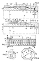
- FIG. 1 illustrates the front end of a large-caliber weapon barrel 12 which, for example, has a caliber diameter d2 of 155 mm and on the outside receives a muzzle brake 10.1 in a manner known per se.
- the muzzle brake 10.1 can be placed coaxially to the barrel core axis 16 at the muzzle end of the gun barrel 12 up to a radially extending annular stop 20 and contains an internal thread 42 which can be screwed onto a corresponding external thread of the gun barrel 12 for fastening the muzzle brake 10.1.
- a spring 44 engaging in a groove 46 of the weapon barrel 12 secures the muzzle brake 12.1 against rotation.
- the muzzle brake 10.1 is given a defined position by a lock nut 62.
- the lock nut 62 is connected behind the muzzle brake 10.1 via a thread to the weapon barrel 12 and, when countered, shifts the muzzle brake 10.1 in the front direction 53, whereby, however, the stop 20 of the muzzle brake 10.1 is released by a gap 66 from the end face 36 of the weapon barrel 12 .
- the seal 64 which consists, for example, of an elastomer, can be destroyed by hot powder gases and powder residues and, in addition, corrosion damage caused by water and moisture on the centering bore 19 of the muzzle brake and on the centering jacket 21 of the weapon barrel 12 and, if appropriate, can occur on the mounting thread 42.
- the lock nut 62 had to be additionally secured against twisting and the spring 44 against radial removal by means of a securing element 58 which can be screwed onto the muzzle brake 10.1 by means of screws 60.
- FIGS. 2 to 5 illustrate the design and attachment of the muzzle brake 10 according to the invention at the front end of the weapon barrel 12.
- the muzzle brake 10 is connected to the weapon barrel 12 at its rear end enveloping the weapon barrel 12 via a separate tensioning device 22 and can be preloaded in a defined manner.
- the tensioning device 22 exerts a high tensile force on the rear end of the muzzle brake 10, so that the stop surface 20 of the muzzle brake 10 is pressed tightly against the end face 38 of the weapon barrel muzzle end.
- the clamping device consists of a flange 28 connected to the weapon barrel 12, which contains axially extending bores 32 for receiving screws 30, while the muzzle brake 10 has threaded bores 34 on the end face in a cylindrical extension 50 for fastening the screws 30.
- the screws 30 of the clamping device 22 consist of a high-strength material, preferably steel, with a minimum tensile strength of 1200 N / mm2.
- the flange 28 is supported in a space-saving manner via a fine thread 36 with respect to the weapon barrel 12.
- the high-strength screws 30 can be heavily loaded despite their space-saving dimensioning and therefore have a self-locking effect due to their high pretensioning force, so that additional screw locking elements can be omitted.
- the high, in the rearward direction 52, tensile force of the screws 30 is transmitted from the stop surface 20 of the muzzle brake 10 to the front end surface 38 of the weapon barrel 12, whereby a specific surface pressure of, for example, 200 N / mm2 with good between the stop surface 20 and the end surface 38 Sealing effect, in particular also against a gas pressure of 800 bar existing during the shooting operation.
- the centering 19, 21 and the thread 42 are thereby protected against corrosion damage, the use of the known sealing ring 64 being unnecessary.
- the muzzle brake 10 can be secured against rotation by a spring 44 with the screw connection 48 as before.
- the tensioning device according to the invention enables the thread 42 and the spring 44 with the groove 46 to be eliminated even due to the high pretension.
- Figures 3 to 5 show the gas outlet openings 14 arranged in the lateral length region of the muzzle brake 10 transversely to the tube core axis 16, the rear gas outlet opening 14 having a minimum opening length l 1.
- the axial inner bore 18 of the muzzle brake 10 has a pull diameter d 1 and not the caliber diameter d 2 of the weapon barrel 12 corresponding inner diameter d, its rear end ending on the surface of the radially extending stop 20.
- the gas outlet openings 14 have baffle and sliding surfaces 24, 26 which have a different opening length 1 in the rear area of the muzzle brake 10 and an identical opening length 1 in the front area, each with a constant opening width b.
- the opening length l1 increases up to half the effective length l2 of the muzzle brake 10 and remains constant in the subsequent half of the length l2.
- the angles .alpha., .Beta. Of the baffle surface 24 and the sliding surface 26 are designed at different angles to the inner bore 18.
- the angle ⁇ of the baffle surface 24 ensures an optimal deflection of the outlet gases in an angular range of 100 to 105 ° to the inner bore 18 and, in cooperation with the gas outlet openings 14 corresponding to the maximum opening length l 1, a 50% reduction in return energy of the weapon barrel 12.
- the return energy can be reduced from 1200 kN to 600 kN.
- the angle ⁇ of the gas guide surface 26 ensures an interference-free gas discharge in an angular range from 110 to 120 ° to the inner bore 18.
- a particularly favorable braking effect of the weapon barrel 12 is achieved when the baffle surface 24 is arranged at an angle ⁇ of 102 ° and the gas guide surface 26 is arranged at an angle ⁇ of 114 ° with respect to the inner bore 18, the baffle surface 24 also having a diameter d3 outgoing approach 54 can be carried out enlarged.
- the muzzle brake 10 is further characterized by a short design, the effective length l2 of the muzzle brake 10 compared to the caliber diameter d2 of the barrel 12 only having a ratio between 4 and 5.
- the muzzle brake 10 is provided with a large number of gas outlet openings 14, for example with 14 gas outlet openings 14 arranged on both sides.
- the short design and a flattening 56 arranged above and below in the entire length range l 2 of the muzzle brake 10 have a weight-reducing and thus positive effect with regard to the prestressing forces to be applied by the tensioning device.
- the muzzle brake contains a drain opening 40, which is preferably arranged in the rear lower region of the muzzle brake 10.
Landscapes
- Engineering & Computer Science (AREA)
- General Engineering & Computer Science (AREA)
- Portable Nailing Machines And Staplers (AREA)
- Braking Arrangements (AREA)
Description
Die Erfindung betrifft eine Mündungsbremse nach den im Oberbegriff des Patentanspruches 1 angegebenen Merkmalen.The invention relates to a muzzle brake according to the features specified in the preamble of claim 1.
Eine derartige Mündungsbremse ist aus "Militärtechnik" 6/74, Seite 250, Bild 4 und 5 als bekannt zu entnehmen. Aus dieser Druckschrift sind Gasaustrittsöffnungen bekannt, deren vordere Prallfläche und hintere Gleitfläche unter einem unbestimmten Winkel schräg und parallel nach hinten gerichtet sind. Es wird kein Hinweis gegeben, in welchem Winkelbereich der Prallfläche eine maximale Reduzierung der Rücklaufenergie eines Waffenrohres während der Schußabgabe eines drallstabilisierten Geschosses erzielt werden kann. Aus dieser Druckschrift ist es desweiteren bekannt, die Lage der quer zur Rohrseelenachse angeordneten Gasaustrittsöffnungen in unterschiedlicher Länge vom hinteren Ende der Mündungsbremse bis ganz nach vorn ansteigend anzuordnen. Dadurch wird einerseits eine Reduzierung des Knalldruckes und des Mündungsblitzes herbeigeführt, andererseits wird jedoch die Rücklaufenergie des Waffenrohres ungünstig reduziert.Such a muzzle brake can be seen as known from "Military Technology" 6/74, page 250, Figures 4 and 5. From this document gas outlet openings are known, the front impact surface and rear sliding surface of which are directed obliquely and parallel to the rear at an undetermined angle. There is no indication of the angular range of the impact surface in which a maximum reduction in the return energy of a weapon barrel can be achieved during the firing of a spin-stabilized projectile. From this document it is also known to arrange the position of the gas outlet openings arranged transversely to the tube core axis in different lengths from the rear end of the muzzle brake to the front. On the one hand, this results in a reduction in the blast pressure and the flash of the muzzle, but on the other hand the return energy of the weapon barrel is disadvantageously reduced.
Diese Mündungsbremse enthält darüber hinaus keine durchgehende Innenbohrung, sondern im Bereich der Austrittsöffnungen über den Rohrinnendurchmesser hinausgehende Erweiterungen. Beim Geschoßdurchgang wird dadurch im Bereich der Erweiterungen der vorhandene Gasdruck im Waffenrohr schnell abgebaut, so daß im Bereich der Mündungsbremse keine weitere oder ggf. nur eine geringe Geschwindigkeitserhöhung des Geschosses erzielt werden kann.In addition, this muzzle brake does not contain a continuous inner bore, but rather extensions in the area of the outlet openings that go beyond the pipe inner diameter. When passing through the projectile, the existing gas pressure in the weapon barrel is quickly reduced in the area of the extensions, so that no further or possibly only a slight increase in the speed of the projectile can be achieved in the area of the muzzle brake.
Aus den Druckschriften FR-A-1597401 und US-A-4 545 285 sind separate, d. h. an das Waffenrohr anschraubbare Mündungsbremsen bekannt, deren Innendurchmesser exakt dem Innendurchmesser des Waffenrohres und somit dem Kaliberdurchmesser der Munition entsprechen. Aus der Druckschrift US-A 4 545 285 wird auch ersichtlich, daß für Waffenrohre mit Zugprofil Schwierigkeiten bestehen, die Mündungsbremse zu separieren. Die Figuren 7 bis 9 lassen deshalb nur einstückig mit dem Waffenrohr verbundene Mündungsbremsen mit Zugprofil erkennen. Bei dem Problem eine separate Mündungsbremse an ein mit Zügen versehenes Waffenrohr anzuschließen, sind besondere Schwierigkeiten zu überwinden, deren Lösung auch aus dem vorgenannten Stand der Technik nicht offenbart wird. Es ist beispielsweise bei einer getrennten Fertigung kein versatzloser Übergang von den Zügen des Waffenrohres zu den Zügen der Mündungsbremse möglich. Ein Wechsel der Mündungsbremse ist dadurch auch ausgeschlossen. Des weiteren werden durch die im Bereich der Mündungsbremse befindlichen Züge während des Geschoßdurchlaufs auf eine separate Mündungsbremse vergleichsweise hohe Drehmomente erzeugt, die in den Verbindungselementen zum Waffenrohr ein Setzen des Materials und daraus resultierend im Übergangsbereich des Waffenohres zur Mündungsbremse Undichtigkeiten verursachen können.FR-A-1597401 and US-A-4 545 285 disclose separate, e.g. H. muzzle brakes which can be screwed onto the gun barrel are known, the inside diameter of which corresponds exactly to the inside diameter of the gun barrel and thus the caliber diameter of the ammunition. From document US-A 4 545 285 it can also be seen that there are difficulties for gun barrels with a towing profile to separate the muzzle brake. FIGS. 7 to 9 therefore only show muzzle brakes with a tension profile that are connected in one piece to the weapon barrel. In the case of the problem of connecting a separate muzzle brake to a weapon barrel provided with trains, particular difficulties have to be overcome, the solution of which is also not disclosed from the aforementioned prior art. For example, in the case of separate production, it is not possible to make a seamless transition from the barrel of the gun barrel to the barrel brake. A change of the muzzle brake is also excluded. Furthermore, the trains located in the area of the muzzle brake generate a comparatively high torque when passing through the storey on a separate muzzle brake, which can cause the material to set in the connecting elements to the weapon barrel and, as a result, leakage in the transition area of the weapon ear to the muzzle brake.
Die eingangs beschriebene Mündungsbremse bedarf beim Einsatz an einem großkalibrigen Waffenrohr noch einer zusätzlichen stabilen Sicherung. Sie kann wie eine in der DE-32 03 807 A1 dargestellte Mündungsbremse im Bereich eines das Waffenrohr umhüllenden Gewindeteiles durch eine in das Waffenrohr eingreifende Feder gegen Verdrehen gesichert werden, wobei sie vorher durch eine in der Figur 1 der vorliegenden Erfindung dargestellte Kontermutter noch verspannt und die Feder aufwendig gegen radiales Loslösen gesichert werden muß.The muzzle brake described at the beginning requires an additional stable securing when used on a large-caliber weapon barrel. Like a muzzle brake shown in DE-32 03 807 A1, it can be secured against twisting in the region of a threaded part enveloping the weapon barrel by a spring engaging in the weapon barrel, previously braced and locked by a lock nut shown in FIG. 1 of the present invention the spring must be secured against radial detachment.
Durch den Verspannungsvorgang der Kontermutter wird jedoch das Gewindeteil im Bereich des Gewindespieles nach vorn geschoben, so daß ein Spalt zwischen der vorderen Stirnseite des Waffenrohres und einer radialen Anschlagfläche entsteht.By tightening the lock nut, however, the threaded part is pushed forward in the area of the thread play, so that a gap is created between the front end of the weapon barrel and a radial stop surface.
Durch den Spalt können Pulvergase und Feuchtigkeit beispielsweise die Lebensdauer einer eingesetzten Elastomerdichtung beeinträchtigen, wodurch Folgeschäden durch Korrosion im Befestigungsbereich der Mündungsbremse entstehen können.Through the gap, powder gases and moisture can, for example, impair the service life of an elastomer seal used, which can result in consequential damage due to corrosion in the attachment area of the muzzle brake.
Aus der GB-A-18491 AD 1912 ist eine Mündungsbremse bekannt, die aus übereinander gestapelten Scheiben gebildet und flanschartig über lange Stiftschrauben zusammengeschraubt wird. Das hintere Bolzenende dient dem Zweck, die Mündungsbremse über keilförmig ausgebildete Schalen auf dem Waffenrohr zu befestigen. Für den Aufbau und die Befestigung der Mündungsbremse sind aufwendig sehr viele Einzelteile erforderlich, deren Setzverhalten durch ihre Gesamtverschraubung an der Anschlagfläche der Mündungsbremse am vorderen Waffenrohrende Undichtigkeiten nicht ausschließt.From GB-A-18491 AD 1912 a muzzle brake is known which is formed from disks stacked one above the other and is screwed together like a flange using long stud bolts. The rear end of the bolt serves the purpose of fastening the muzzle brake to the weapon barrel via wedge-shaped shells. For the construction and attachment of the muzzle brake, many individual parts are required, the setting behavior of which does not rule out leaks due to their overall screwing on the muzzle brake stop surface at the front end of the barrel.
Aus der US-A-4 811 648 ist eine Mündungsbremse für eine Handfeuerwaffe als bekannt zu entnehmen, die jedoch bereits in dem von der Mündungsbremse überlappenden Teil des vorderen Waffenrohres Bohrungen als Gasaustrittsöffnungen aufweist, und vor dem Waffenrohr weitere Gasaustrittsöffnungen enthält, die großer als der Innendurchmesser des Waffenrohres sind. Die in der Länge über den Innendurchmesser des Waffenrohres hinausgehenden Gasaustrittsöffnungen verursachen jedoch einen schnellen Gasdruckabfall innerhalb der Mündungsbremse und somit eine geringere Anfangsgeschwindigkeit des Geschosses, gleichzeitig jedoch eine Vergrößerung des Knalldruckes und Verstärkung des seitlichen Feuerblitzes.From US-A-4 811 648 a muzzle brake for a handgun is known to be known, but which already has bores as gas outlet openings in the part of the front weapon barrel overlapping the muzzle brake and contains further gas outlet openings in front of the weapon tube which are larger than that Are inside diameter of the barrel. However, the gas outlet openings extending in length beyond the inside diameter of the weapon barrel cause a rapid gas pressure drop within the muzzle brake and thus a lower initial velocity of the projectile, but at the same time an increase in the blast pressure and an increase in the side firing flash.
Demgegenüber ist es Aufgabe der Erfindung, eine Mündungsbremse bereitzustellen, die nicht nur gegenüber der eingangs zitierten Mündungsbremse den Wirkungsgrad verbessert und die Einsatzbereitschaft wesentlich verlängert, sondern auch die Geschoßanfangsgeschwindigkeit erhöht.In contrast, it is an object of the invention to provide a muzzle brake which not only improves the efficiency and significantly increases the readiness for use compared to the muzzle brake cited at the beginning, but also increases the initial velocity of the projectile.
Gelöst wird diese Aufgabe durch die im kennzeichnenden Teil des Patentanspruchs 1 angegebenen Merkmale.This object is achieved by the features specified in the characterizing part of patent claim 1.
Vorteilhafte Ausgestaltungen der Erfindung gehen aus den Merkmalen der Unteransprüche hervor.Advantageous embodiments of the invention emerge from the features of the subclaims.
Die erfindungsgemäße Mündungsbremse erzielt vorzugsweise bei einem Einsatz an großkalibrigen Rohrwaffen, beispielsweise an Waffenrohren von Feld- oder Panzerhaubitzen, wesentlich Vorteile.The muzzle brake according to the invention preferably achieves significant advantages when used on large-caliber barrel weapons, for example on gun barrels of field or armored howitzers.
Dadurch, daß die axiale Innenbohrung der Mündungsbremse einen dem Zugdurchmesser des Waffenrohres entsprechenden Innendurchmesser aufweist und ihr hinteres Ende an der Fläche des radial verlaufenden Anschlages endet, können beim Geschoßdurchlauf seitlich am Geschoß wenig Gase vorbeiströmen, wodurch der Gasdruckabbau innerhalb der Mündungsbremse vergleichweise gering bleibt und eine Steigerung der Geschoßanfangsgeschwindigkeit um beispielsweise 20 m/sec erzielt wird.Because the axial inner bore of the muzzle brake has an inner diameter corresponding to the draw diameter of the weapon barrel and its rear end ends at the surface of the radially extending stop, little gases can flow past the projectile during the projectile passage, whereby the gas pressure reduction within the muzzle brake remains comparatively low and one Increase in the initial velocity of the projectile, for example by 20 m / sec.
Die seitlichen Gasaustrittsöffnungen weisen ausgehend vom Zugdurchmesser im hinteren Bereich der Mündungsbremse eine unterschiedliche, maßgeblich in vordere Richtung zunehmende Öffnungslänge auf, während die Gasaustrittsöffnungen im vorderen Bereich der Mündungsbremse eine gleiche Öffnungslänge aufweisen. Die vergleichsweise kurze Öffnungslänge erzeugt in der ersten hinteren Durchlaufphase des Geschosses eine Reduzierung des Knalldruckes und des Mündungsblitzes, während in der zweiten vorderen Durchlaufphase des Geschosses die Gase in voller Schlitzlänge gegen die Prallflächen strömen, wodurch die Rücklaufenergie des Waffenrohres mit einem hohen Wirkungsgrad von beispielsweise 50 % gebremst wird. Der hohe Wirkungsgrad wird beispielsweise dann erzielt, wenn der Winkel der Prallfläche in einem Winkelbereich von 100 bis 105 ° zur Innenbohrung und der Winkel der Gasleitfläche in einem Winkelbereich von 110 bis 120° zur Innenbohrung angeordnet sind.The lateral gas outlet openings have a different opening length, starting from the train diameter in the rear area of the muzzle brake, which increases significantly in the front direction, while the gas outlet openings in the front area of the muzzle brake have the same opening length. The comparatively short opening length produces a reduction in the impact pressure and the muzzle flash in the first rear passage phase of the projectile, while in the second front passage phase of the projectile the gases flow against the baffles in full slot length, whereby the return energy of the barrel with a high efficiency of, for example, 50 % is braked. The high efficiency is achieved, for example, when the angle of the impact surface is arranged in an angular range from 100 to 105 ° to the inner bore and the angle of the gas guide surface in an angular range from 110 to 120 ° to the inner bore.
Die erfindungsgemäße Mündungsbremse ist an ihrem hinteren das Waffenrohr umhüllenden Ende über eine separate Spannvorrichtung mit dem Waffenrohr verbunden und definiert vorspannbar, wobei die Spannvorrichtung eine hohe Zugkraft auf das hintere Ende der Mündungsbremse ausübt, so daß die Anschlagfläche dichtend an der Stirnseite des Waffenrohrmündungsendes angepreßt anliegt. Die dichtende Anlage der Anschlagfläche der Mündungsbremse an der Stirnseite des Waffenrohres verhindert das Eindringen der aus dem Waffenrohr ausströmenden Pulvergase und von Feuchtigkeit, wodurch im Befestigungsbereich Schäden durch Korrosion verhindert werden. Die Mündungsbremse ist somit auch leicht de- und montierbar.The muzzle brake according to the invention is connected at its rear end encasing the weapon barrel to the weapon barrel via a separate tensioning device and can be preloaded in a defined manner, the tensioning device exerting a high tensile force on the rear end of the muzzle brake, so that the stop surface is pressed tightly against the end face of the weapon barrel muzzle end. The sealing abutment of the muzzle brake stop on the front of the gun barrel prevents penetration the powder gases escaping from the gun barrel and moisture, which prevents damage from corrosion in the fastening area. The muzzle brake is therefore also easy to disassemble and assemble.
Nach einem Ausgestaltungsmerkmal besteht die Spannvorrichtung aus einem am Waffenrohr angeschlossenen Flansch, der den Einsatz von kleindimensionierten hochfesten Schrauben gestattet, die selbstsichernd und hochvorspannbar sind und somit auf einfache Weise eine hohe Flächenpressung und dadurch die gewünschte Dichtwirkung zwischen der Anschlagfläche der Mündungsbremse und der Stirnseite des Waffenrohres erzielen.According to a design feature, the clamping device consists of a flange connected to the barrel, which allows the use of small-sized, high-strength screws that are self-locking and can be preloaded and thus easily apply high surface pressure and thus the desired sealing effect between the stop surface of the muzzle brake and the front of the barrel achieve.
Ausgehend von dem bekannten Stand der Technik wird die Erfindung anhand eines in den Figuren dargestellten Ausführungsbeispieles des näheren erläutert.Based on the known prior art, the invention is explained in more detail using an exemplary embodiment shown in the figures.
Es zeigt:
- Figur 1:
- ausschnittsweise den Befestigungsbereich einer bekannten Mündungsbremse an einem großkalibrigen Waffenrohr mit bisher üblichen Befestigungselementen,
- Figur 2:
- ausschnittsweise den Befestigungsbereich der erfindungsgemäßen Mündungsbremse an einem großkalibrigen Waffenrohr,
- Figur 3:
- einen Längsschnitt durch die Mündungsbremse,
- Figur 4
- einen in der Figur 3 mit IV-IV gekennzeichneten Querschnitt,
- Figur 5:
- einen in der Figur 4 mit V-V gekennzeichneten Schnittverlauf.
- Figure 1:
- sections of the fastening area of a known muzzle brake on a large-caliber weapon barrel with previously usual fastening elements,
- Figure 2:
- sections of the fastening area of the muzzle brake according to the invention on a large-caliber weapon barrel,
- Figure 3:
- a longitudinal section through the muzzle brake,
- Figure 4
- 3 shows a cross section identified by IV-IV in FIG. 3,
- Figure 5:
- a section marked VV in FIG. 4.
Die Figur 1 verdeutlicht das vordere Ende eines großkalibrigen Waffenrohres 12, das beispielsweise einen Kaliberdurchmesser d₂ von 155 mm aufweist und außenseitig eine Mündungsbremse 10.1 in an sich bekannter Weise aufnimmt. Die Mündungsbremse 10.1 ist koaxial zur Rohrseelenachse 16 an das Mündungsende des Waffenrohres 12 bis zu einem radial verlaufenden ringförmigen Anschlag 20 ansetzbar und enthält ein Innengewinde 42, das zur Befestigung der Mündungsbremse 10.1 auf ein entsprechendes Außengewinde des Waffenrohres 12 aufschraubbar ist. Eine in eine Nute 46 des Waffenrohres 12 eingreifende Feder 44 sichert die Mündungsbremse 12.1 gegen Verdrehen. Damit die Mündungsbremse 10.1 während des Schießbetriebes sich nicht innerhalb des Gewindespieles axial bewegen kann, erhält die Mündungsbremse 10.1 durch eine Kontermutter 62 eine definierte Lage. Die Kontermutter 62 ist hinter der Mündungsbremse 10.1 über ein Gewinde mit dem Waffenrohr 12 verbunden und verschiebt beim Kontern die Mündungsbremse 10.1 in die vordere Richtung 53, wodurch jedoch der Anschlag 20 der Mündungsbremse 10.1 um einen Spalt 66 von der Stirnseite 36 des Waffenrohres 12 gelöst wird. Dadurch können die eingangs genannten Nachteile auftreten, wobei die beispielsweise aus einem Elastomer bestehende Dichtung 64 durch heiße Pulvergase und Pulverreste zerstört werden kann und zusätzlich durch Wasser und Feuchtigkeit hervorgerufene Korrosionsschäden an der Zentrierbohrung 19 der Mündungsbremse und an dem Zentriermantel 21 des Waffenrohres 12 sowie ggf. an dem Befestigungsgewinde 42 auftreten können. Bei dieser bisherigen Befestigungsweise der Mündungsbremse mußte die Kontermutter 62 zusätzlich gegen Verdrehen und die Feder 44 gegen radiales Entfernen durch ein mittels Schrauben 60 auf der Mündungsbremse 10.1 anschraubbares Sicherungselement 58 gesichert werden.FIG. 1 illustrates the front end of a large-
Demgegenüber verdeutlichen die Figuren 2 bis 5 die Gestaltung und Befestigung der erfindungsgemäßen Mündungsbremse 10 am vorderen Ende des Waffenrohres 12.In contrast, FIGS. 2 to 5 illustrate the design and attachment of the
Nach der Figur 2 ist die Mündungsbremse 10 an ihrem hinteren das Waffenrohr 12 umhüllenden Ende über eine separate Spannvorrichtung 22 mit dem Waffenrohr 12 verbunden und definiert vorspannbar. Die Spannvorrichtung 22 übt eine hohe Zugkraft auf das hintere Ende der Mündungsbremse 10 aus, so daß die Anschlagfläche 20 der Mündungsbremse 10 dichtend an der Stirnseite 38 des Waffenrohrmündungsendes angepreßt anliegt.According to FIG. 2, the
Die Spannvorrichtung besteht aus einem am Waffenrohr 12 angeschlossenen Flansch 28, der zur Aufnahme von Schrauben 30 axial verlaufende Bohrungen 32 enthält, während die Mündungsbremse 10 in einem zylindrischen Ansatz 50 stirnseitig Gewindebohrungen 34 zur Befestigung der Schrauben 30 aufweist. Die Schrauben 30 der Spannvorrichtung 22 bestehen aus einem hochfesten Werkstoff, vorzugsweise Stahl, mit einer Mindestzugfestigkeit von 1200 N/mm². Der Flansch 28 stützt sich raumsparend über ein Feingewinde 36 gegenüber dem Waffenrohr 12 ab.The clamping device consists of a
Die hochfesten Schrauben 30 können trotz ihrer raumsparenden Dimensionierung hoch belastet werden und wirken deshalb durch ihre hohe Vorspannkraft selbstsichernd, so daß zusätzliche Schraubensicherungselemente entfallen können. Die hohe in rückwärtige Richtung 52 weisende Zugkraft der Schrauben 30 wird von der Anschlagfläche 20 der Mündungsbremse 10 auf die vordere Stirnfläche 38 des Waffenrohres 12 abstützend übertragen, wodurch zwischen der Anschlagfläche 20 und der Stirnfläche 38 eine spezifische Flächenpressung von beispielsweise 200 N/mm² mit guter Dichtwirkung, insbesondere auch gegen einen während des Schießbetriebes vorhandenen Gasdruck von 800 bar erzeugt wird. Die Zentrierung 19, 21 und das Gewinde 42 werden dadurch vor Korrosionsschäden geschützt, wobei der Einsatz des bekannten Dichtringes 64 entbehrlich ist. Die Mündungsbremse 10 kann wie bisher durch eine Feder 44 mit der Schraubverbindung 48 gegen Verdrehen gesichert sein. Nach einem nicht dargestellten Ausführungsbeispiel ermöglicht die erfindungsgemäße Spannvorrichtung sogar durch die hohe Vorspannung den Wegfall des Gewindes 42 und der Feder 44 mit Nute 46.The high-strength screws 30 can be heavily loaded despite their space-saving dimensioning and therefore have a self-locking effect due to their high pretensioning force, so that additional screw locking elements can be omitted. The high, in the
Die Figuren 3 bis 5 lassen die im seitlichen Längenbereich der Mündungsbremse 10 quer zur Rohrseelenachse 16 angeordneten Gasaustrittsöffnungen 14 erkennen, wobei die hintere Gasaustrittsöffnung 14 eine minimale Öffnungslänge l₁ aufweist.Figures 3 to 5 show the
Die axiale Innenbohrung 18 der Mündungsbremse 10 weist einen dem Zugdurchmesser d₁ und nicht dem Kaliberdurchmesser d₂ des Waffenrohres 12 entsprechenden Innendurchmesser d auf, wobei ihr hinteres Ende an der Fläche des radial verlaufenden Anschlages 20 endet. Diese Ausführung erzielt den Vorteil, daß neben der bereits erwähnten Erhöhung der Geschoßanfangsgeschwindigkeit die Geschoßdrehzahl im Bereich der Mündungsbremse nicht mehr erhöht wird und dadurch zusätzliche Geschoßbelastungen vermieden werden.The axial inner bore 18 of the
Ausgehend von dem Zugdurchmesser d weisen die Gasaustrittsöffnungen 14 Prall- und Gleitflächen 24, 26 auf, die im hinteren Bereich der Mündungsbremse 10 eine unterschiedliche und im vorderen Bereich eine gleiche Öffnungslänge 1 bei jeweils konstanter Öffnungsbreite b aufweisen. Die Öffnungslänge l₁ nimmt bis zur Hälfte der wirksamen Länge l₂ der Mündungsbremse 10 gleichmäßig zu und bleibt in der anschließenden Hälfte der Länge l₂ konstant. Die Winkel α, β der Prallfläche 24 und der Gleitfläche 26 sind unterschiedlich schräg gegenüber der Innenbohrung 18 ausgeführt.Starting from the train diameter d, the
Der Winkel α der Prallfläche 24 gewährleistet in einem Winkelbereich von 100 bis 105 ° zur Innenbohrung 18 eine optimale Umlenkung der Austrittsgase und im Zusammenwirken mit den der maximalen Öffnungslänge l₁ entsprechenden Gasaustrittsöffnungen 14 eine 50 %ige Rücklaufenergiereduzierung des Waffenrohres 12. Bei einem Waffenrohr 12 von 155 Kaliberdurchmesser d₂ kann beispielsweise die Rücklaufenergie von 1200 kN auf 600 kN reduziert werden.The angle α of the
Der Winkel β der Gasleitfläche 26 sorgt in einem Winkelbereich von 110 bis 120 ° zur Innenbohrung 18 für eine störungsfreie Gasableitung. Ein besonders günstiger Bremseffekt des Waffenrohres 12 wird dann erzielt, wenn die Prallfläche 24 unter einem Winkel α von 102 ° und die Gasleitfläche 26 unter einem Winkel β von 114 ° gegenüber der Innenbohrung 18 angeordnet sind, wobei die Prallfläche 24 noch durch einen über den Durchmesser d₃ hinausgehenden Ansatz 54 vergrößter ausgeführt sein kann.The angle β of the
Die Mündungsbremse 10 zeichnet sich desweiteren durch eine kurze Bauweise aus, wobei die wirksame Länge l₂ der Mündungsbremse 10 gegenüber dem Kaliberdurchmesser d₂ des Waffenrohres 12 nur ein Verhältnis zwischen 4 und 5 aufweist. In dieser wirksamen Länge l₂ ist die Mündungsbremse 10 mit einer hohen Anzahl von Gasaustrittsöffnungen 14 beispielsweise mit jeweils 14 beidseitig angeordneten Gasaustrittsöffnungen 14 versehen.The
Die kurze Bauweise und eine im gesamten Längenbereich l₂ der Mündungsbremse 10 oben und unten angeordnete Abflachung 56 wirken sich gewichtsreduzierend und somit positiv hinsichtlich der durch die Spannvorrichtung aufzubringenden Vorspannkräfte aus.The short design and a flattening 56 arranged above and below in the entire
Zur Vermeidung von Feuchtigkeits- bzw. Wasseransammlungen im Waffenrohr 12 enthält die Mündungsbremse eine Abflußöffnung 40, die vorzugsweise im hinteren unteren Bereich der Mündungsbremse 10 angeordnet ist.To avoid moisture or water accumulation in the
Claims (10)
- Muzzle brake for a gun barrel (12), the muzzle brake being attachable coaxially to the muzzle end of the barrel as far as an annular stop lying radially, the rear end of the internal boring (18) of the muzzle brake terminating at the radial surface of the stop and containing in a lateral longitudinal zone gas outlet apertures (14) which are positioned transversally to the axis (16) of the barrel bore and which have a minimum aperture length (1₁) at the rear end of the muzzle brake (10), characterised by the fact-- that the axial internal boring (18) of the muzzle brake (10) has an internal diameter (d) corresponding to the rifling diameter (d₁) of the barrel (12),-- that the muzzle brake (10), at the rear end encasing the barrel (12), is connected by a separate clamping device (22) with the barrel (12) and can be given a defined prestressing, the clamping device consisting of a flange (28) which is integrally connected to the barrel (12) and which is provided with axial borings (32) serving to accommodate bolts (30), and that the muzzle brake (10) is provided in front with screw-threaded borings (34) as a means of securing the bolts (30), which exert high tensile force on the rear end of the muzzle brake (10) so that the stop surface (20) bears firmly against the end face (38) of the barrel muzzle end with a sealing effect,-- that starting from the rifling diameter (d) the gas outlet apertures (14) are provided with deflection and gas conduction surfaces (24,26) which in the rear zone of the muzzle brake (10) have a different, and in the front zone an equal aperture length (1₁) which is smaller than the rifling diameter (d).
- Muzzle brake in accordance with Claim 1, characterised by the fact that the bolts (30) of the clamping device (22) consist of a high-strength material with a minimum tensile strength of 1200 N/mm².
- Muzzle brake in accordance with Claim 1, characterised by the fact that the flange (28) is connected via a fine threading (36) with the barrel (12).
- Muzzle brake in accordance with Claim 1, characterised by the fact that the aperture length (1₁) of the gas outlet apertures (14) increases constantly as far as half the effective length (1₂) of the muzzle brake (10) and remains constant in the subsequent half of the length (1₂).
- Muzzle brake in accordance with Claim 1, characterised by the fact that the angles (α, β) of the deflection surface (24) and of the gas conducting surface (26) slant at a different angle with respect to the internal boring (18).
- Muzzle brake in accordance with Claim 5, characterised by the fact that the angle (α) of the deflection surface (24) is in an angular range of 100-105° with respect to the internal boring (18) and the angle (β) of the gas conducting surface (26) is in an angular range of 110-120° with respect to the internal boring (18).
- Muzzle brake in accordance with Claims 5 and 6, characterised by the fact that the deflection surface (24) is positioned at an angle of (α) of 102° and the gas conducting surface (26) is positioned at an angle (β) of 114° with respect to the internal boring (18).
- Muzzle brake in accordance with any one of Claims 1 to 7, characterised by the fact that the effective length (1₂) of the barrel brake (10) bears a ratio of between 4 and 5 in relation to the calibre diameter (d2) of the barrel (12).
- Muzzle brake in accordance with any one of Claims 1 to 8, characterised by a flat part (56) provided on the top and on the bottom over the entire length (1₂) of the muzzle brake (10).
- Muzzle brake in accordance with any one of Claims 1 to 19, characterised by a discharge aperture (40) preferably situated in the lower rear zone of the muzzle brake (10).
Applications Claiming Priority (2)
| Application Number | Priority Date | Filing Date | Title |
|---|---|---|---|
| DE4025546A DE4025546C2 (en) | 1990-08-11 | 1990-08-11 | Muzzle brake for a large-caliber barrel weapon |
| DE4025546 | 1990-08-11 |
Publications (2)
| Publication Number | Publication Date |
|---|---|
| EP0471920A1 EP0471920A1 (en) | 1992-02-26 |
| EP0471920B1 true EP0471920B1 (en) | 1995-02-22 |
Family
ID=6412105
Family Applications (1)
| Application Number | Title | Priority Date | Filing Date |
|---|---|---|---|
| EP91105675A Expired - Lifetime EP0471920B1 (en) | 1990-08-11 | 1991-04-10 | Muzzle brake for large-caliber gun |
Country Status (3)
| Country | Link |
|---|---|
| US (1) | US5119716A (en) |
| EP (1) | EP0471920B1 (en) |
| DE (2) | DE4025546C2 (en) |
Families Citing this family (17)
| Publication number | Priority date | Publication date | Assignee | Title |
|---|---|---|---|---|
| US5279200A (en) * | 1992-07-13 | 1994-01-18 | Browning | Ballistic optimizing system for rifles |
| FR2729464A1 (en) * | 1995-01-18 | 1996-07-19 | Giat Ind Sa | MOUTH BRAKE FOR MEDIUM OR LARGE CALIBER GUNS |
| US5698810A (en) * | 1995-11-29 | 1997-12-16 | Browning Arms Company | Convertible ballistic optimizing system |
| US6223458B1 (en) | 1997-04-30 | 2001-05-01 | Kevin Schwinkendorf | Harmonic optimization technology |
| US5798473A (en) * | 1997-04-30 | 1998-08-25 | Roblyer; Steven | Harmonic optimization system for rifles |
| US6668699B2 (en) * | 1998-08-20 | 2003-12-30 | Ronnie David Russell | Porous nozzle projectile barrel |
| US6752062B2 (en) * | 2001-12-07 | 2004-06-22 | George M. Vais | Muzzle brake |
| US6782651B1 (en) * | 2003-02-12 | 2004-08-31 | Inpromarketing Corp. | Breaching tool |
| US7143680B2 (en) * | 2003-04-08 | 2006-12-05 | Bender Terrence D | Recoil and muzzle blast dissipator |
| US7581482B1 (en) * | 2005-07-28 | 2009-09-01 | The United States Of America As Represented By The Secretary Of The Army | Supersonic turning vane |
| DE102007024515A1 (en) | 2007-05-24 | 2008-11-27 | Rheinmetall Waffe Munition Gmbh | Apparatus and method for attaching a muzzle brake to a gun barrel |
| US8025003B1 (en) * | 2009-10-14 | 2011-09-27 | The United States Of America As Represented By The Secretary Of The Navy | Fluted firearm barrel |
| DE102016000437A1 (en) * | 2016-01-18 | 2017-07-20 | Prime Manufacturing Group Limited (BVI) | Device for releasably securing a silencer and silencer assembly |
| US10619964B2 (en) * | 2017-01-11 | 2020-04-14 | Palmetto State Armory, LLC | Modified pistol upper |
| US10337820B2 (en) * | 2017-11-21 | 2019-07-02 | John Jager | Firearm muzzle device clamp |
| USD868197S1 (en) | 2017-12-13 | 2019-11-26 | In Ovation, LLC | Firearm compensator |
| USD1022106S1 (en) | 2021-09-29 | 2024-04-09 | In Ovation Llc | Firearm compensator |
Family Cites Families (16)
| Publication number | Priority date | Publication date | Assignee | Title |
|---|---|---|---|---|
| DE169838C (en) * | ||||
| GB167728A (en) * | 1921-02-10 | 1921-08-18 | Schneider & Cie | Improvements in apparatus for reducing the length of recoil in guns |
| US1363058A (en) * | 1921-02-10 | 1920-12-21 | T F Shanahn | Car construction |
| GB184911A (en) * | 1921-05-31 | 1922-08-31 | Harry Lawley Milner | Improvements in or relating to cocks and valves |
| US1605393A (en) * | 1925-07-20 | 1926-11-02 | Jr Richard M Cutts | Climb arrester |
| BE410174A (en) * | 1934-07-16 | |||
| GB454533A (en) * | 1936-02-03 | 1936-10-02 | Vickers Armstrongs Ltd | Improvements in or relating to means for modifying the recoil of a gun |
| FR958162A (en) * | 1947-05-31 | 1950-03-04 | ||
| US3141376A (en) * | 1955-06-13 | 1964-07-21 | George M Chinn | Flame-out eliminator |
| DE1553895A1 (en) * | 1967-04-01 | 1972-04-13 | Tampella Oy Ab | Pipe end or mouthpiece on pipes for non-twist projectiles |
| US3703122A (en) * | 1970-12-10 | 1972-11-21 | Gen Electric | Muzzle brake torque assist for multi-barrel weapons |
| US4207799A (en) * | 1977-02-14 | 1980-06-17 | Tocco Charles T | Muzzle brake |
| DE3203807A1 (en) * | 1982-02-04 | 1983-08-11 | Rheinmetall GmbH, 4000 Düsseldorf | Muzzle brake |
| US4545285A (en) * | 1982-06-15 | 1985-10-08 | Mclain Clifford E | Matched expansion muzzle brake |
| US4811648A (en) * | 1987-09-14 | 1989-03-14 | Blackwell David L | Muzzle brake device |
| US4919035A (en) * | 1989-03-06 | 1990-04-24 | Pinkston Mark C | Muzzle brake and tool for installation |
-
1990
- 1990-08-11 DE DE4025546A patent/DE4025546C2/en not_active Expired - Fee Related
-
1991
- 1991-04-10 EP EP91105675A patent/EP0471920B1/en not_active Expired - Lifetime
- 1991-04-10 DE DE59104666T patent/DE59104666D1/en not_active Expired - Fee Related
- 1991-06-28 US US07/723,062 patent/US5119716A/en not_active Expired - Lifetime
Also Published As
| Publication number | Publication date |
|---|---|
| US5119716A (en) | 1992-06-09 |
| DE59104666D1 (en) | 1995-03-30 |
| DE4025546A1 (en) | 1992-02-13 |
| DE4025546C2 (en) | 2002-03-14 |
| EP0471920A1 (en) | 1992-02-26 |
Similar Documents
| Publication | Publication Date | Title |
|---|---|---|
| EP0471920B1 (en) | Muzzle brake for large-caliber gun | |
| EP1338859B1 (en) | Gun barrel with muzzle brake | |
| EP2867607B1 (en) | Silencer for a firearm | |
| EP0660915B1 (en) | Gun silencer | |
| DE69604097T2 (en) | Muzzle brake for a medium or large caliber gun | |
| DE60012269T2 (en) | Device for attaching a muzzle brake to a gun barrel | |
| DE2057995A1 (en) | Handgun with exchangeable barrel | |
| DE202018005980U1 (en) | System for quick assembly and disassembly of a silencer on the barrel of a firearm | |
| EP0291845A1 (en) | Projectile with core and jacket | |
| DE19841585A1 (en) | Gun barrel with a collimator holder arranged in the area of the muzzle | |
| EP0221917B1 (en) | Undercalibrated projectile | |
| DE3322979A1 (en) | DEVICE FOR FIXING AND TENSIONING AN INSERTION TUBE IN A WEAPON TUBE | |
| EP0089000B1 (en) | Projectile with armour-piercing core | |
| DE602006000111T2 (en) | Guide tape for artillery round | |
| DE19704489C2 (en) | Sub-caliber sabot bullet | |
| DE2227656A1 (en) | LOWER CALIBER FLOOR | |
| DE19504840B4 (en) | Projectile with a penetrator arranged in a metal shell | |
| DE102006056662A1 (en) | Projectile body for barrel of fire arm, has ring shaped recess provided in body in shooting direction behind ring shaped dome, which is squeezable in recess during acceleration phase of body in barrel of fire arm | |
| DE3046639A1 (en) | Gun-barrel accessory reducing error angle - comprises stiffener over entire length of barrel to reduce torsional oscillation | |
| EP0560078A2 (en) | Device for reducing the impact of shock waves, mounted on the barrel of a gun | |
| WO2009156031A1 (en) | Sabot projectile | |
| DE2856859A1 (en) | Gyroscopically stabilised practice missile - has braking system composed of fins hinged circumferentially around body which fly out under centrifugal force | |
| DE10254975B3 (en) | High-load thin-walled multi-part tube structure, e.g. for missile, has gap-separated teeth at end sectors of both parts in at least two radial planes | |
| DE42924C (en) | Gun barrel, which is composed of metal disks normal to the axis of the soul | |
| DE202023101932U1 (en) | Quick connect system, silencer and firearm |
Legal Events
| Date | Code | Title | Description |
|---|---|---|---|
| PUAI | Public reference made under article 153(3) epc to a published international application that has entered the european phase |
Free format text: ORIGINAL CODE: 0009012 |
|
| 17P | Request for examination filed |
Effective date: 19911211 |
|
| AK | Designated contracting states |
Kind code of ref document: A1 Designated state(s): DE FR GB IT NL |
|
| RAP3 | Party data changed (applicant data changed or rights of an application transferred) |
Owner name: RHEINMETALL GMBH |
|
| 17Q | First examination report despatched |
Effective date: 19931007 |
|
| ITF | It: translation for a ep patent filed | ||
| RAP1 | Party data changed (applicant data changed or rights of an application transferred) |
Owner name: RHEINMETALL INDUSTRIE GMBH |
|
| GRAA | (expected) grant |
Free format text: ORIGINAL CODE: 0009210 |
|
| AK | Designated contracting states |
Kind code of ref document: B1 Designated state(s): DE FR GB IT NL |
|
| GBT | Gb: translation of ep patent filed (gb section 77(6)(a)/1977) |
Effective date: 19950224 |
|
| REF | Corresponds to: |
Ref document number: 59104666 Country of ref document: DE Date of ref document: 19950330 |
|
| ET | Fr: translation filed | ||
| PLBE | No opposition filed within time limit |
Free format text: ORIGINAL CODE: 0009261 |
|
| STAA | Information on the status of an ep patent application or granted ep patent |
Free format text: STATUS: NO OPPOSITION FILED WITHIN TIME LIMIT |
|
| 26N | No opposition filed | ||
| PGFP | Annual fee paid to national office [announced via postgrant information from national office to epo] |
Ref country code: NL Payment date: 19970331 Year of fee payment: 7 |
|
| PG25 | Lapsed in a contracting state [announced via postgrant information from national office to epo] |
Ref country code: NL Free format text: LAPSE BECAUSE OF NON-PAYMENT OF DUE FEES Effective date: 19981101 |
|
| NLV4 | Nl: lapsed or anulled due to non-payment of the annual fee |
Effective date: 19981101 |
|
| REG | Reference to a national code |
Ref country code: GB Ref legal event code: IF02 |
|
| PGFP | Annual fee paid to national office [announced via postgrant information from national office to epo] |
Ref country code: DE Payment date: 20030331 Year of fee payment: 13 |
|
| PGFP | Annual fee paid to national office [announced via postgrant information from national office to epo] |
Ref country code: GB Payment date: 20040331 Year of fee payment: 14 |
|
| PGFP | Annual fee paid to national office [announced via postgrant information from national office to epo] |
Ref country code: FR Payment date: 20040415 Year of fee payment: 14 |
|
| PG25 | Lapsed in a contracting state [announced via postgrant information from national office to epo] |
Ref country code: DE Free format text: LAPSE BECAUSE OF NON-PAYMENT OF DUE FEES Effective date: 20041103 |
|
| PG25 | Lapsed in a contracting state [announced via postgrant information from national office to epo] |
Ref country code: IT Free format text: LAPSE BECAUSE OF NON-PAYMENT OF DUE FEES Effective date: 20050410 Ref country code: GB Free format text: LAPSE BECAUSE OF NON-PAYMENT OF DUE FEES Effective date: 20050410 |
|
| GBPC | Gb: european patent ceased through non-payment of renewal fee |
Effective date: 20050410 |
|
| PG25 | Lapsed in a contracting state [announced via postgrant information from national office to epo] |
Ref country code: FR Free format text: LAPSE BECAUSE OF NON-PAYMENT OF DUE FEES Effective date: 20051230 |
|
| REG | Reference to a national code |
Ref country code: FR Ref legal event code: ST Effective date: 20051230 |