EP0470482B1 - Vorrichtung zum Drehen einer Platte oder eines Pakets von Platten auf einem Arbeitstisch von einer Schneidmaschine - Google Patents
Vorrichtung zum Drehen einer Platte oder eines Pakets von Platten auf einem Arbeitstisch von einer Schneidmaschine Download PDFInfo
- Publication number
- EP0470482B1 EP0470482B1 EP91112770A EP91112770A EP0470482B1 EP 0470482 B1 EP0470482 B1 EP 0470482B1 EP 91112770 A EP91112770 A EP 91112770A EP 91112770 A EP91112770 A EP 91112770A EP 0470482 B1 EP0470482 B1 EP 0470482B1
- Authority
- EP
- European Patent Office
- Prior art keywords
- panel stack
- gripping means
- panel
- stack
- cutting machine
- Prior art date
- Legal status (The legal status is an assumption and is not a legal conclusion. Google has not performed a legal analysis and makes no representation as to the accuracy of the status listed.)
- Expired - Lifetime
Links
- 238000005520 cutting process Methods 0.000 title claims abstract description 82
- 230000033001 locomotion Effects 0.000 claims abstract description 7
- 238000010276 construction Methods 0.000 claims description 5
- 238000007796 conventional method Methods 0.000 claims description 3
- 238000006243 chemical reaction Methods 0.000 claims description 2
- 230000005540 biological transmission Effects 0.000 claims 2
- 230000002452 interceptive effect Effects 0.000 description 2
- 239000000463 material Substances 0.000 description 2
- 238000011144 upstream manufacturing Methods 0.000 description 2
- 239000006096 absorbing agent Substances 0.000 description 1
- 238000010586 diagram Methods 0.000 description 1
- 238000006073 displacement reaction Methods 0.000 description 1
- 238000012986 modification Methods 0.000 description 1
- 230000004048 modification Effects 0.000 description 1
- 230000035939 shock Effects 0.000 description 1
- 238000009966 trimming Methods 0.000 description 1
Images


Classifications
-
- B—PERFORMING OPERATIONS; TRANSPORTING
- B27—WORKING OR PRESERVING WOOD OR SIMILAR MATERIAL; NAILING OR STAPLING MACHINES IN GENERAL
- B27B—SAWS FOR WOOD OR SIMILAR MATERIAL; COMPONENTS OR ACCESSORIES THEREFOR
- B27B31/00—Arrangements for conveying, loading, turning, adjusting, or discharging the log or timber, specially designed for saw mills or sawing machines
- B27B31/04—Turning equipment
-
- B—PERFORMING OPERATIONS; TRANSPORTING
- B21—MECHANICAL METAL-WORKING WITHOUT ESSENTIALLY REMOVING MATERIAL; PUNCHING METAL
- B21D—WORKING OR PROCESSING OF SHEET METAL OR METAL TUBES, RODS OR PROFILES WITHOUT ESSENTIALLY REMOVING MATERIAL; PUNCHING METAL
- B21D43/00—Feeding, positioning or storing devices combined with, or arranged in, or specially adapted for use in connection with, apparatus for working or processing sheet metal, metal tubes or metal profiles; Associations therewith of cutting devices
- B21D43/02—Advancing work in relation to the stroke of the die or tool
- B21D43/04—Advancing work in relation to the stroke of the die or tool by means in mechanical engagement with the work
- B21D43/10—Advancing work in relation to the stroke of the die or tool by means in mechanical engagement with the work by grippers
-
- B—PERFORMING OPERATIONS; TRANSPORTING
- B21—MECHANICAL METAL-WORKING WITHOUT ESSENTIALLY REMOVING MATERIAL; PUNCHING METAL
- B21D—WORKING OR PROCESSING OF SHEET METAL OR METAL TUBES, RODS OR PROFILES WITHOUT ESSENTIALLY REMOVING MATERIAL; PUNCHING METAL
- B21D43/00—Feeding, positioning or storing devices combined with, or arranged in, or specially adapted for use in connection with, apparatus for working or processing sheet metal, metal tubes or metal profiles; Associations therewith of cutting devices
- B21D43/02—Advancing work in relation to the stroke of the die or tool
- B21D43/04—Advancing work in relation to the stroke of the die or tool by means in mechanical engagement with the work
- B21D43/14—Advancing work in relation to the stroke of the die or tool by means in mechanical engagement with the work by turning devices, e.g. turn-tables
-
- B—PERFORMING OPERATIONS; TRANSPORTING
- B23—MACHINE TOOLS; METAL-WORKING NOT OTHERWISE PROVIDED FOR
- B23D—PLANING; SLOTTING; SHEARING; BROACHING; SAWING; FILING; SCRAPING; LIKE OPERATIONS FOR WORKING METAL BY REMOVING MATERIAL, NOT OTHERWISE PROVIDED FOR
- B23D47/00—Sawing machines or sawing devices working with circular saw blades, characterised only by constructional features of particular parts
- B23D47/04—Sawing machines or sawing devices working with circular saw blades, characterised only by constructional features of particular parts of devices for feeding, positioning, clamping, or rotating work
-
- B—PERFORMING OPERATIONS; TRANSPORTING
- B27—WORKING OR PRESERVING WOOD OR SIMILAR MATERIAL; NAILING OR STAPLING MACHINES IN GENERAL
- B27B—SAWS FOR WOOD OR SIMILAR MATERIAL; COMPONENTS OR ACCESSORIES THEREFOR
- B27B5/00—Sawing machines working with circular or cylindrical saw blades; Components or equipment therefor
- B27B5/02—Sawing machines working with circular or cylindrical saw blades; Components or equipment therefor characterised by a special purpose only
- B27B5/06—Sawing machines working with circular or cylindrical saw blades; Components or equipment therefor characterised by a special purpose only for dividing plates in parts of determined size, e.g. panels
Definitions
- the invention relates to an apparatus for turning by 90° a panel or a panel stack on the worktable of a cutting machine, particularly for a pre-cutting operation and then a normal cutting operation to be performed in a panel or panel stack by a longitudinally cutting machine, according to the pre-characterizing part of claim 1.
- the object of the invention is to provide an apparatus for turning by 90° a panel or a panel stack on the worktable of a cutting machine according to the pre-characterizing part of claim 1, in which the worktable has reduced overall dimensions and can be made by conventional techniques.
- the apparatus according to the invention allows a reduction of the floor space of the worktable for supporting a panel stack as it is being turned by 90° and permits the said worktable being made with conventional techniques, while its construction is not of a special type, as it is instead required in the known art.
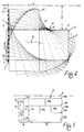
- Figure 1 is a plan view showing a possible panel-pre-cutting pattern to be carried out on a panel stack.
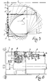
- Figures 2 and 3 are plan views of a diagram illustrating how a panel stack is turned by the apparatus of the invention.
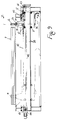
- Figures 4 and 5 are side views with parts in section, of the gripping means for holding a panel stack while it is being turned, which show the various operative and rest positions of the same.
- FIG. 6 is a sectional view of this gripping means, taken on line VI-VI in Figure 4, and showing some details of the same.
- FIG. 7 is a sectional view of this gripping means, taken on line VII-VII in Figure 6, and showing a further detail of the same.
- Figure 8 is a top plan view of the gripping means fitted on the pusher carriage of the longitudinally cutting machine.
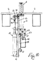
- Figure 9 is a side view of the downwardly withdrawable pushing means that in combination with the gripping means according to the preceding Figures, causes a panel stack to be turned.
- Figure 10 is a view with parts in cross-section of the pushing means according to Figure 9, taken on line X-X, and showing some details of the same.
- reference P denotes a panel or a panel stack
- reference Z denotes the cutting line of the first longitudinally cutting machine in an angular cutting plant, by which this panel stack should be cut, for example, according to the cutting pattern shown in this Figure.
- a panel stack P is usually placed on the worktable before the cutting line Z of the said longitudinally cutting machine, with its long sides being arranged parallel thereto.
- the just cut stacked panel strips will be then acted upon by the pusher or pushers of the second, normally transversely cutting machine, to the cutting line of which these strips are advanced for the longitudinal cuts T4, T5, T6, T7, T8 to be made in the said part A.
- the panel stack part B left on the worktable of the first longitudinally cutting machine is turned by 90° and returned into the condition as shown in Figure 1, so that the said part will be then advanced to the cutting line Z of the said first machine, for the longitudinal cuts T9, T10, T11, T12 to be made therein.
- the transverse cuts T13, T14, T15, T16 will be made in the stacked panel strips resulting from the said cuts T9-T12.
- the invention relates to an apparatus for a panel stack P to be subjected to the above-disclosed 90° panel-stack-turning steps.
- the said panel stack-turning apparatus comprises a gripping means 1 which is for clamping a panel stack P at a point of its perimeter, and which is rotatable around a vertical axis 2, and is shiftable near to, and away from the cutting line Z of the longitudinally cutting machine, along the straight line 3 which is parallel to, and coincides with, or is at a short distance from the "zero" datum side of the said longitudinally cutting machine worktable Q, i. e, the side that is the left-hand side in the shown example, in which respect the positioning of a panel stack remains always the same with any different panel stack sizes.
- Such shiftments of the gripping means must be programmable as a function of the size of a panel pack P and, for this purpose, the gripping means 1 can be fitted with advantage on the carriage mounting the gripper members associated with the pusher of the first machine normally making longitudinal cuts at its cutting line Z, which carriage is already provided with motor means for programmable precise shiftments to be effected.
- the gripping means 1 is operated by servo controls, by which this gripping means is rotated around its axis 2 so as to be properly oriented for correctly clamping a panel stack during the panel stack-turning steps, and is vertically shifted along the said axis so as to be moved from an uplifted position in which it is prevented from interfering with a panel stack, into a lowered down position in which it is caused to cooperate with a panel stack (see hereinafter).
- the panel stack-turning apparatus of the invention comprises a pushing means preferably in form of a freely rotatable, vertical axis roller 4, which upon control can be lifted from the worktable Q supporting a panel stack P, up to a level being at least equal to the thickness thereof, and which must be withdrawable under the said worktable, in order to be prevented from interfering with a panel stack.
- This pushing roller is fitted on a carriage which is movable along a line 5 being parallel to the cutting line Z of the longitudinally cutting machine, and lying at a proper distance D therefrom.
- the worktable Q supporting a panel stack P is formed at the line 5 along which the pushing roller 4 is motivated, with an elongated rectilinear aperture arranged parallel to the cutting line Z of the longitudinally cutting machine, and being suitably wide for the roller 4 to be allowed to run therein.
- the said panel stack-supporting worktable Q may be of any known construction and may be, for example, of the modular type.
- the thus conceived apparatus is operated as follows.
- a panel stack P is at first placed on the worktable of the longitudinally cutting machine, in front of its cutting line Z, and is positioned as shown by P' in Figure 2.
- the forward long side of this panel stack is arranged upstream of, and at a short distance from the elongated aperture 5 in which the pushing roller 4 is caused to run, the said roller being moved into the position 4' and being lifted up before this panel stack.
- the uplifted gripping means 1 is moved behind this panel stack P, into the position shown by 1', and is then lowered down and caused to clamp the panel stack by its rear long side, close to the corner V1 thereof.
- the lowered down gripping means is being advanced toward the cutting line Z of the longitudinally cutting machine and is caused to reach the position 1'', and the uplifted pushing roller 4 is being shifted in timed relation from the position 4' to the position 4''.
- the panel stack P is turned by 90° so that from the position shown by P' the same is moved into the position shown by P'', as required for a pre-cutting operation to be performed in its part A.
- the broken line 6 shows how the barycenter of the panel stack is being displaced while the panel stack is being turned by the apparatus of the invention.
- the gripping means 1 and the pushing roller 4 are mutually neutralized, and the stacked panels may be driven against one or more left-hand side arranged, stacked panels line-up means of the withdrawable type, not shown, for example by the pushing roller 4, and may be by another roller mounted on its own motivating means, by which this other roller is moved parallel to the line 5.
- the stacked panels being lined up, even a not too close tolerance can be allowed in the 90° turning of the panel stack by the apparatus according to the invention, with the advantages resulting from such a lined-up condition of the stacked panels.
- the stacked panels After the stacked panels having been turned and may be lined up, the stacked panels are acted upon by the gripper members associated with the pusher of the first, normally longitudinally cutting machine, and are advanced to the cutting line Z thereof for the transverse cuts T1, T2, T3 to be made in its part A, as stated above by referring to Figure 1.
- the remaining panel stack part B ( Figure 1) is moved backward into the position shown for example by P''' in Figure 3.
- the pusher associated with the first machine making longitudinal cuts at its cutting line Z now drives the gripping means 1 into the position shown by 1''', so that this gripping means will be allowed to nextly clamp the remaining panel stack part B by its one long side, close to the corner V2.
- the pushing roller 4 is located in the position shown by 4''', and is uplifted.
- the pushing roller 4 is lowered down, the gripping means 1 is set in open condition and is lifted up, and the part B of the panel stack P, which may be pushed against left-hand side arranged, line-up means, is then advanced to the cutting line Z of the longitudinally cutting machine, for the longitudinal cuts T9-T12 to be made therein.
- a support 8 is fixedly connected to the upper part of the pusher carriage 7 of the first machine normally making longitudinal cuts at its cutting line Z, and a bushing 10 with its axis being vertically arranged, is rotatably carried by the said support through bearings 9.
- a crown gear 11 Coaxially keyed to the outside of said bushing is a crown gear 11 which is in mesh with a rack 12 driven by a cylinder-and-piston unit 13 coaxially fastened by its rear end side to the fore end side of a further cylinder-and-piston unit 14, whose stem 15 is fixedly connected at 16 to the pusher carriage 7.
- Reference numerals 17 and 18 denote magnetic sensors for detecting the end-of-stroke positions of the pistons of the said pneumatically operated units 13 and 14.
- the bushing 10 is formed with a longitudinal slot engaged by a key 19 for a tube 20 to be slidably guided thereby in the said bushing, which tube carries at its upper end a projectingly arranged plate 21 made integral therewith, to which the body is fastened of a cylinder-and-piston unit 22, with its stem being vertically directed downward, and being fastened to a plate 23 made integral with the upper end of the said bushing 10.
- the backward and forward vertical stroke of the stem of the cylinder-and-piston unit 22 results in the tube 20 being accordingly lifted up and lowered down.
- Pivotally connected at 24 to the lower end of tube 20, are the upper ends of the one transversally arranged jaw member 25 of the gripping means 1, which in front view has a "U"-shaped configuration as shown in Figure 6, while in side view the same has and "L"-shaped configuration, as shown in Figure 4.
- Reference numeral 26 denotes a suitable, elastic/yieldable added material which is for covering the inward flat face of the foot 125 of the said one jaw member 25.
- the legs of the one jaw member 25 of the gripping means 1 have a respective slot 27 formed in their inward sides, with its uppermost section 127 being suitably inclined, and with the rest thereof extending straight along the longitudinal axis of the jaw member legs.
- Set in cooperation with the slots 27 are two pins 28 arranged in opposite positions, which are carried by a crosspiece 29 being fixedly connected to the lower end of a stem 30 which is axially slidably fitted in tube 20, and is fastened to the stem of a cylinder-and-piston unit 31 whose body is fastened to the plate 21.
- This crosspiece 29 constitutes the other jaw member of the gripping means, and has its downward flat face provided with a covering 32 made from a suitable elastic/yieldable material.
- the gripping means upper jaw member 29 is being lowered down, and according to the operative sequence shown in Figure 5, before the jaw member 29 having been moved into contact with a panel stack P, this jaw member moves the pins 28 into cooperation with the straight section of slots 27, whereby a swinging movement of the jaw member 25 is promoted, which results in its foot 125 being slipped by its active part 26 under the panel stack P, however without the same being allowed to interfere therewith.
- the gripping means is made to correspond to the height dimension of the panel stack without lifting the same, in that the cylinder-and-piston unit 22 is set in its inoperative condition, or is in a condition in which it reacts in a resilient manner.
- the jaw member 25 can be so provided and/or so positioned relative to a panel stack P, that this jaw member will be either caused to contact the panel stack at one of its end sides, as shown in Figure 5, or to not come in touch therewith.
- the cylinder-and-piston unit 22 is set in operative condition, so that the upper jaw member is at first moved into its uplifted position, and the lower jaw member is then swung away from a panel stack by the said upper jaw member.
- the gripping means having been thus arranged in open condition, is lifted up.
- the worktable Q supportig a panel stack P is so provided that the panel stack edge portion lying over the line 3, along which the gripping means 1 is motivated, is left in such a free condition that it does not interfere with the gripping means when the same is run through its active travel.
- this roller 4 is vertically and freely rotatably fitted on a slide 33 which by means of rollers 34 is caused to slide in a slot 35 vertically formed in a carriage 36, consisting of a plate arranged in upright position, with grooved wheels 37 being mounted on one of its sides so as to project therefrom, and running on a fixed straight guide 38 arranged in an underlying parallel relation with the elongated aperture 5 in the worktable Q, through which the said pushing roller is lifted up, to be disposed in operative condition.
- the carriage 36 With the interposition of at least one shock absorber, the carriage 36 is connected to the ends of a toothed belt or chain 42 led over horizontal axis sprockets 43, 43', one of which is driven by a motive unit 44 with an electronically controlled motor. Provisions may be made for the ends of chain 42 to be connected to the double stem of a pneumatically operated cylinder unit 45 whose body is fastened to the carriage 36. Thanks to the provision of this unit, the said carriage 36 can be imparted any movements with a resilient character, independently from the above-disclosed, programmed precise shiftments by the aforementioned motor means, which are, for example, useful when the roller 4 will have to be used as a means for orderly arranging stacked panels against sidewise located line-up means.
Landscapes
- Engineering & Computer Science (AREA)
- Mechanical Engineering (AREA)
- Life Sciences & Earth Sciences (AREA)
- Wood Science & Technology (AREA)
- Forests & Forestry (AREA)
- Stacking Of Articles And Auxiliary Devices (AREA)
- Finish Polishing, Edge Sharpening, And Grinding By Specific Grinding Devices (AREA)
- Cartons (AREA)
- Details Of Rigid Or Semi-Rigid Containers (AREA)
- Forklifts And Lifting Vehicles (AREA)
- Details Of Cutting Devices (AREA)
- Diaphragms For Electromechanical Transducers (AREA)
- Fats And Perfumes (AREA)
- Specific Conveyance Elements (AREA)
Claims (7)
- Vorrichtung zum Drehen einer Platte oder eines Plattenstapels (P) auf dem Arbeitstisch (Q) einer Schneidmaschine, insbesondere zum Vorschneiden, gefolgt von einem normalen Schneidverfahren an einer Platte oder einem Plattenstapel (P) mit Hilfe einer in Längsrichtung schneidenden Maschine, wobei die Vorrichtung folgende Merkmale aufweist:a) Greifmittel (1), die zurückgezogen werden können, die um eine vertikale Achse (2) gedreht werden können, und die, bei Anliegen eines entsprechenden Steuerungssignals, einen Plattenstapel (P) im Bereich einer der Ecken des Stapels klammernd greifen können und die mit einer Verschiebeeinrichtung (7) verbunden ist, die zu programmierbaren, präzisen Verschiebungen dient derart, daß der Plattenstapel (P) im Uhrzeigersinn oder im Gegenuhrzeigersinn gedreht wird,b) Schiebemittel (4), die ebenfalls zurückgezogen werden können, und die zusammen mit den Greifmitteln (1) auf den Plattenstapel (P) programmierbar einwirken, so daß die gewünschte Drehung des Plattenstapels (P) unterstützt wird,
dadurch gekennzeichnet,c) daß das Greifmittel eine gerade Bewegung (3) auf die Schneidlinie (Z) der Längs-Schneidmaschine zu- und von ihr wieder hinweg ausführt,d) daß das Greifmittel (1) einen Plattenstapel (P) im Gebiet einer ihrer rückwärtigen Ecken greift, und daß der Plattenstapel (P) im Uhrzeigersinn oder im Gegenuhrzeigersinn gedreht wird, abhängig davon, ob der Plattenstapel benachbart seiner linken Ecke oder seiner rechten Ecke gegriffen wird,e) daß das Schiebeelement (4) auf einen Plattenstapel (P) dadurch einwirkt, daß es parallel zur Schneidlinie (Z) der Längs-Schneidmaschine einwirkt,f) daß die gesamte Anordnung so ausgebildet ist, daß der für den Arbeitstisch (Q) benötigte Platz zum Halten eines Plattenstapels (P) verringert wird, wenn dieser um 90° gedreht wird, wobei der Arbeitstisch übliche Techniken und auch keine spezielle Konstruktion aufweist. - Vorrichtung nach Anspruch 1,
dadurch gekennzeichnet,
daß das Greifmittel (1) zum Drehen eines Plattenstapels am Schlitten (7) für den Schieber der Längs-Schneidmaschine angepaßt ist, der normalerweise so betätigt wird, daß er programmierbar und präzise bewegt wird, wobei Vorsorge dafür getroffen ist, daß das Greifmittel, je nach Bedarf, neutralisiert oder in den Betriebszustand eingestellt werden kann, beispielsweise indem es entweder angehoben oder abgesenkt wird, wobei das Greifmittel so am Schlitten befestigt ist, daß es um seine vertikale Achse (2) gedreht werden kann, und zwar unter der Steuerung von Mitteln (11, 12, 13, 14) zum Drehen dieses Bauteils, welches bei Vorliegen eines entsprechenden Steuerungssignals das Greifmittel im Winkel richtig positioniert, so daß das Greifmittel entweder für den ersten oder für den zweiten Drehschritt des Stapels richtig ausgerichtet ist, wie dies entweder für das Vorschneiden des Stapels oder für das Zurückbringen des verbleibenden Stapelteils (B) in dessen vorhergehende Anordnung relativ zur Schneidlinie (Z) der Längs-Schneidmaschine notwendig ist. - Vorrichtung nach Anspruch 1,
dadurch gekennzeichnet,
daß eine programmierbare Steuerung vorgesehen ist, mit der das Greifmittel (1) einen Plattenstapel an seiner rückwärtigen Längsseite greift, und zwar benachbart der Ecke (V1) des Stapels, so daß bei dem ersten Drehschritt für den Stapel der Plattenstapel um 90° um eine vertikale Achse gedreht wird und dadurch so angeordnet wird, daß seine Längsseiten rechtwinkelig zur Schneidlinie (Z) der Längs-Schneidmaschine verlaufen, wobei diese Ecke (V1) mit der Nullseite des Arbeitstisches der Längs-Schneidmaschine zusammenfällt oder sich in deren Nähe befindet, wobei das Positionieren eines Plattenstapels auch bei unterschiedlichen Großen des Plattenstapels stets unverändert bleibt, wobei weiterhin Vorsorge dafür getroffen ist, daß beim Starten des ersten Schritts zum Drehen des Stapels die Schiebeeinrichtung (4) vor der Längsseite des Plattenstapels positioniert wird, und zwar an einem Zwischenpunkt, so daß in zeitlich abgestimmter Beziehung mit der verschobenen Greifeinrichtung das Schiebemittel (4) nahe zu der Linie (3) bewegt wird, längs derer die Greifeinrichtung verschoben wird, bis die Längsseiten des Plattenstapels um 90° gedreht worden sind. - Vorrichtung nach Anspruch 1,
dadurch gekennzeichnet,
daß programmierbare Steuerungsmittel vorgesehen sind, mit deren Hilfe die Greifeinrichtung (1) den Plattenstapel an derjenigen Längsseite klammernd gegriffen wird, die zur Nullseite des Arbeitstisches der Schneidmaschine gedreht wird, und zwar benachbart derjenigen Kante (V2) zwischen dieser Längsseite des Stapels und der rückwärtigen kürzeren Seite des Plattenstapels, so daß beim zweiten Drehungsschritt des Plattenstapels ein Plattenstapel um 90° um eine vertikale Achse gedreht wird und dadurch in seinem früheren Zustand relativ zur Schneidlinie (Z) der Längs-Schneidmaschine wieder angeordnet wird, wobei das Schiebemittel (4) am Anfang dieses zweiten Drehschritts für den Stapel sich benachbart der Längsseite des Plattenstapels befindet und an einem Zwischenpunkt dieser Längsseite des Plattenstapels, auf den die Greifeinrichtung eingewirkt hat und die gesteuert hinweg von der Linie (3) bewegt wird, und zwar zusammen mit der Greifeinrichtung, die aktiviert ist, bis die betreffende Längsseite des Plattenstapels um 90° gedreht worden ist. - Vorrichtung nach den vorhergehenden Patentansprüchen,
dadurch gekennzeichnet,
daß das Greifmittel (1) zum Klammern und Drehen eines Plattenstapels eine Klaue (25) aufweist, die in einer Seitenansicht L-förmig profiliert ist, die an ihren oberen Enden (24) horizontal schwenkbar an das untere Ende eines vertikal angeordneten Rohres (20) angelenkt ist, welches in einer Buchse (10) axial gleitend angeordnet ist, mit der das Rohr fest verbunden ist, wobei die Buchse so befestigt ist, daß sie um ihre Achse gedreht werden kann, und zwar mit Hilfe einer Stütze (8), die fest mit dem oberen Teil des Schiebeschlittens (7) der Längs-Schneidmaschine verbunden ist, wobei eine vorspringende Platte (21) am oberen Ende des Rohres befestigt ist, wobei fernerhin der Körper einer vertikal angeordneten, pneumatisch betätigten Kolben-Zylinder-Einheit (22) an der Platte (21) befestigt ist, während die nach unten gerichtete Stange der Einheit (22) mit einer Platte (23) verbunden ist, die mit dem oberen Ende der Buchse (10) verbunden ist, so daß das Teil aus der Buchse vorsteht und wobei eine Stange (30) so vorgesehen ist, daß sie axial in dem Rohr gleiten kann und mit ihrem oberen Ende mit der Stange einer pneumatisch betätigten Kolben-Zyinder-Einheit (31) verbunden ist, deren Körper mit der Platte (21) am oberen Ende des Rohres verbunden ist, welche Stange (30) an ihrem unteren Ende die flache andere Klaue (29) der Greifeinrichtung trägt, die mit Stiften (28) in die Enden an einer Fortsetzung des Teils eingepaßt ist, wobei die Stifte gleitend in Längsschlitzen (27) vorgesehen sind, die in den Innenseiten des L-förmigen unteren Klauengliedes (25) geformt sind, wobei weiterhin jedes Teil einen geneigten obersten Abschnitt (127) aufweist, so daß, wenn das Teil von den Stiften gegriffen wird, das untere Klauenglied eine geneigte Position einnimmt, so daß der untere Teil oder der Fuß (125) dieses Teils in Bezug auf die Projektion des oberen Klauengliedes in einer Draufsicht versetzt wird, wobei weiterhin das untere Klauenglied in einer derartigen geneigten Position angeordnet wird, wobei das untere Klauenglied des Greifelements dann nach unten abgesenkt wird, und wobei das obere Klauenglied des Greifelements anschließend gesteuert abgesenkt wird, so daß, weil die Stifte vom oberen Klauenglied nach unten bewegt werden, und zwar während des ersten Teils der nach unten gerichteten Bewegung, so daß sie mit dem geraden Abschnitt der Schlitze in den Innenseiten des unteren Klauenglieds zusammenwirken, so daß eine derartige Schwenkbewegung des unteren Klauenglieds verursacht wird, daß sein Fuß (125) unter den Plattenstapel gleitet, aber ohne daß der Fuß damit zusammenstößt, und sobald das obere Klauenglied seine nach unten gerichtete Bewegung dadurch beendet hat, daß es in Kontakt mit dem Plattenstapel kommt, daß dann durch eine Reaktion das untere Klauenglied vom oberen Klauenglied angehoben wird, so daß der Plattenstapel von dem Greifmittel klammernd gegriffen wird. - Vorrichtung nach Anspruch 5,
dadurch gekennzeichnet,
daß die Buchse (10), die drehbar die Greifeinrichtung (1) trägt, um einen Plattenstapel zu klammern, mit einer Zahnscheibe (11) versehen ist, die mit der Außenseite der Buchse verkeilt ist, und die mit einer Zahnstange (12) kämmt, die von den pneumatischen Kolben-Zylinder-Einheiten (13, 14) angetrieben ist, mit deren Hilfe das Greifmittel im Winkel unterschiedlich angeordnet werden kann, so daß es einen Plattenstapel vor den beiden aufeinander folgenden Drehschritten für den Plattenstapel richtig greifen kann. - Vorrichtung nach Anspruch 1,
dadurch gekennzeichnet,
daß die Schieberolle (4), die zusammen mit dem Greifmittel (1) auf einem zu drehenden Plattenstapel einwirkt, vertikal und frei drehbar angeordnet ist, so daß sie mit Hilfe einer geeigneten Kolben-Zylinder-Einheit (40) anhebbar und absenkbar ist, und zwar auf einem Gleitstück (33), das an einem Schlitten (36) befestigt ist, der auf einer horizontal angeordneten Führung (38) gleiten kann, die sich unter dem Arbeitstisch zum Halten des Plattenstapels befindet, und zwar parallel zu der Linie (5), längs derer die Schieberolle bewegt wird, wobei Vorsorge dafür getroffen ist, daß der Schlitten mit Hilfe eines positiven Transmissionsantriebs (42, 43, 43') und mit Hilfe eines elektronisch gesteuerten Getriebemotors (44) präzise betätigt wird, wobei der Bewegungs-Transmissionsantrieb als wesentliches Bauelement die Kombination von Zahnrädern und Zahnriemen aufweist, Kettenräder mit einer Kette oder Zahnräder mit einer Zahnstange.
Applications Claiming Priority (2)
| Application Number | Priority Date | Filing Date | Title |
|---|---|---|---|
| IT1250490 | 1990-08-08 | ||
| IT12504A IT1241889B (it) | 1990-08-08 | 1990-08-08 | Apparato per ruotare un pannello o pacco di pannelli, per diversamente orientare il pacco stesso nei confronti della linea di taglio di una sezionatrice |
Publications (2)
| Publication Number | Publication Date |
|---|---|
| EP0470482A1 EP0470482A1 (de) | 1992-02-12 |
| EP0470482B1 true EP0470482B1 (de) | 1994-12-28 |
Family
ID=11140944
Family Applications (1)
| Application Number | Title | Priority Date | Filing Date |
|---|---|---|---|
| EP91112770A Expired - Lifetime EP0470482B1 (de) | 1990-08-08 | 1991-07-30 | Vorrichtung zum Drehen einer Platte oder eines Pakets von Platten auf einem Arbeitstisch von einer Schneidmaschine |
Country Status (9)
| Country | Link |
|---|---|
| US (1) | US5257900A (de) |
| EP (1) | EP0470482B1 (de) |
| AT (1) | ATE116176T1 (de) |
| AU (1) | AU625651B2 (de) |
| CA (1) | CA2048265C (de) |
| DE (1) | DE69106268T2 (de) |
| ES (1) | ES2065586T3 (de) |
| FI (1) | FI913700A7 (de) |
| IT (1) | IT1241889B (de) |
Cited By (1)
| Publication number | Priority date | Publication date | Assignee | Title |
|---|---|---|---|---|
| AT402705B (de) * | 1995-11-14 | 1997-08-25 | Schelling & Co | Auflagetisch für eine trennsäge |
Families Citing this family (13)
| Publication number | Priority date | Publication date | Assignee | Title |
|---|---|---|---|---|
| IT1259878B (it) * | 1992-05-19 | 1996-03-28 | Dispositivo a pinza particolarmente per la presa e movimentazione di pacchi di pannelli in macchine per la sezionatura dei pannelli stessi | |
| US5806396A (en) * | 1994-08-31 | 1998-09-15 | Kabushiki Kaisha Nca | Automatic fabric pattern matching apparatus |
| IT1309274B1 (it) * | 1999-05-28 | 2002-01-16 | Giben Impianti Spa | Dispositivo per la rotazione di pannelli |
| IT1320963B1 (it) | 2000-03-30 | 2003-12-18 | Giben Impianti Spa | Procedimento e dispositivo per effettuare una serie di tagli aventidifferenti orientazioni su uno o piu' pannelli per mezzo di una |
| ITBO20030645A1 (it) | 2003-10-31 | 2005-05-01 | Giben Int Spa | Dispositivo per la rotazione di pannelli. |
| IT1394667B1 (it) * | 2009-07-08 | 2012-07-13 | Biesse Spa | Macchina per il taglio di pannelli di legno o simili |
| IT1395940B1 (it) * | 2009-10-15 | 2012-11-02 | Macotec S R L | Macchina per il taglio di lastre di vetro e simili, con mezzi per la rotazione di almeno una porzione di lastra. |
| ITRM20120232A1 (it) * | 2012-05-23 | 2013-11-24 | Scm Group Spa | Unità di rotazione. |
| CN105710932A (zh) * | 2016-04-13 | 2016-06-29 | 柳州市悟新木工机械有限公司 | 木材分片机及分片方法 |
| DE102018103870A1 (de) * | 2018-02-21 | 2019-08-22 | Homag Plattenaufteiltechnik Gmbh | Handhabungseinrichtung, Verfahren zum Betreiben einer Handhabungseinrichtung, Werkstückbearbeitungsanlage sowie Bewegungseinrichtung |
| CN112060225A (zh) * | 2020-09-02 | 2020-12-11 | 衡东振好木制品有限公司 | 一种多方位木材切割装置 |
| IT202100010010A1 (it) * | 2021-04-20 | 2022-10-20 | Scm Group Spa | Metodo di posizionamento automatico di un pezzo nella stazione di ingresso di una macchina per la lavorazione di pezzi in legno e simili. |
| CN115647470B (zh) * | 2022-10-18 | 2024-03-29 | 东莞职业技术学院 | 可层叠板材移动装置、板材全自动锯切装置和方法 |
Family Cites Families (11)
| Publication number | Priority date | Publication date | Assignee | Title |
|---|---|---|---|---|
| US3232448A (en) * | 1963-09-09 | 1966-02-01 | Globe Hoist Co | Rotating lift |
| US3466514A (en) * | 1967-06-26 | 1969-09-09 | Ibm | Method and apparatus for positioning objects in preselected orientations |
| IT979106B (it) * | 1973-02-14 | 1974-09-30 | Gabbiani V | Dispositivo per la rotazione automatica nel piano di giacitu ra di pannelli particolarmente per macchine sezionatrici |
| US3884363A (en) * | 1973-09-13 | 1975-05-20 | Bendix Corp | Programmable universal transfer device |
| AT342284B (de) * | 1975-04-07 | 1978-03-28 | Schelling & Co | Aufteilsageanlage, insbesondere buntaufteilsagemaschine |
| DE2805532A1 (de) * | 1978-02-10 | 1979-08-16 | Trumpf Maschinen Ag | Werkzeugmaschine mit einer einstellbaren vorrichtung zum festhalten und verschieben eines werkstuecks gegenueber einem werkzeug |
| AT382548B (de) * | 1980-05-21 | 1987-03-10 | Schelling & Co | Einrichtung zum buntaufteilen von plattenfoermigen werkstuecken |
| US4547115A (en) * | 1984-01-25 | 1985-10-15 | Charbonnet Carl D | Apparatus for transporting and aligning panel-like members |
| DE3607454A1 (de) * | 1985-04-10 | 1986-10-16 | Schelling & Co., Schwarzach, Vorarlberg | Aufteilanlage fuer plattenfoermige werkstuecke |
| SU1268398A1 (ru) * | 1985-06-11 | 1986-11-07 | Фрунзенский политехнический институт | Исполнительный орган манипул тора |
| US5133256A (en) * | 1991-03-11 | 1992-07-28 | Ag Communication Systems Corporation | Printer plate locating device |
-
1990
- 1990-08-08 IT IT12504A patent/IT1241889B/it active IP Right Grant
-
1991
- 1991-07-30 ES ES91112770T patent/ES2065586T3/es not_active Expired - Lifetime
- 1991-07-30 EP EP91112770A patent/EP0470482B1/de not_active Expired - Lifetime
- 1991-07-30 AT AT91112770T patent/ATE116176T1/de not_active IP Right Cessation
- 1991-07-30 DE DE69106268T patent/DE69106268T2/de not_active Expired - Fee Related
- 1991-07-31 AU AU81474/91A patent/AU625651B2/en not_active Ceased
- 1991-08-01 CA CA002048265A patent/CA2048265C/en not_active Expired - Fee Related
- 1991-08-02 FI FI913700A patent/FI913700A7/fi not_active Application Discontinuation
- 1991-08-08 US US07/742,418 patent/US5257900A/en not_active Expired - Lifetime
Cited By (1)
| Publication number | Priority date | Publication date | Assignee | Title |
|---|---|---|---|---|
| AT402705B (de) * | 1995-11-14 | 1997-08-25 | Schelling & Co | Auflagetisch für eine trennsäge |
Also Published As
| Publication number | Publication date |
|---|---|
| AU8147491A (en) | 1992-03-05 |
| FI913700A0 (fi) | 1991-08-02 |
| IT9012504A0 (it) | 1990-08-08 |
| IT9012504A1 (it) | 1992-02-08 |
| DE69106268D1 (de) | 1995-02-09 |
| US5257900A (en) | 1993-11-02 |
| CA2048265A1 (en) | 1992-02-09 |
| CA2048265C (en) | 1995-02-07 |
| ES2065586T3 (es) | 1995-02-16 |
| DE69106268T2 (de) | 1995-05-18 |
| IT1241889B (it) | 1994-02-01 |
| ATE116176T1 (de) | 1995-01-15 |
| AU625651B2 (en) | 1992-07-16 |
| FI913700A7 (fi) | 1992-02-09 |
| EP0470482A1 (de) | 1992-02-12 |
Similar Documents
| Publication | Publication Date | Title |
|---|---|---|
| EP0470482B1 (de) | Vorrichtung zum Drehen einer Platte oder eines Pakets von Platten auf einem Arbeitstisch von einer Schneidmaschine | |
| US6546834B1 (en) | Method and machine for sawing panels with laterally movable pusher | |
| US8020476B2 (en) | Plate-dividing system for dividing plate-shaped workpieces, and method for the operation thereof | |
| US3763547A (en) | Automatic fastening machine | |
| US3733947A (en) | Book trimming machine | |
| EP2845840B1 (de) | Vorrichung und verfahren zum schneiden von verbundenen gasscheiben | |
| EP0106019B1 (de) | Maschine zum automatischen Stapeln von Plattenpaketen mit unterschiedlichen Grössen auf betreffende Hebeplattformen | |
| US3890862A (en) | Apparatus for shearing the edges of a sheet of metal | |
| US3907125A (en) | Apparatus for the delivery and removal of palettes provided with work-pieces on machine tools | |
| US3395596A (en) | Disappearing table | |
| US5279342A (en) | Woodworking machine | |
| CN109850622B (zh) | 智能物流裁切生产线 | |
| DE2134375B2 (de) | Selbsttätig arbeitende Vorrichtung zum Beschicken von Schneidemaschinen mit gestapeltem Gut und zum Abführen und Stapeln des geschnittenen Gutes mittels zweier der Maschine zugeordneter Liftsäulen, an denen ein verfahrbarer Träger zur Aufnahme des Schneidgutes angeordnet ist | |
| GB1219419A (en) | Improvements in or relating to machines for drilling and/or marking workpieces | |
| EP1138455A2 (de) | Verfahren und Vorrichtung zum Ausführen mehrerer Schnitte unterschiedlicher Winkel in einem Werkstück oder in mehreren Werkstücken unter Verwendung einer Plattensäge | |
| US3768352A (en) | Method and apparatus for cutting panels | |
| GB1586737A (en) | Closed loop machining system | |
| US3570561A (en) | Installation for subdividing a flat workpiece | |
| GB2125729A (en) | End-forming of timber strips and an end-forming woodworking machine | |
| CN217350117U (zh) | 一种理袋机 | |
| US5711641A (en) | Method and device for loading and unloading printed circuit boards on a machine tool | |
| US5198039A (en) | Apparatus and method for automatically positioning and operating non-contact tool holders | |
| JPH06170788A (ja) | 自動断裁装置 | |
| US3157333A (en) | Machine for operating on elongated workpieces | |
| KR910004929Y1 (ko) | 부품자동삽입기의 기판 이동장치 |
Legal Events
| Date | Code | Title | Description |
|---|---|---|---|
| PUAI | Public reference made under article 153(3) epc to a published international application that has entered the european phase |
Free format text: ORIGINAL CODE: 0009012 |
|
| AK | Designated contracting states |
Kind code of ref document: A1 Designated state(s): AT BE CH DE DK ES FR GB GR LI LU NL SE |
|
| 17P | Request for examination filed |
Effective date: 19920326 |
|
| 17Q | First examination report despatched |
Effective date: 19930630 |
|
| GRAA | (expected) grant |
Free format text: ORIGINAL CODE: 0009210 |
|
| AK | Designated contracting states |
Kind code of ref document: B1 Designated state(s): AT BE CH DE DK ES FR GB GR LI LU NL SE |
|
| PG25 | Lapsed in a contracting state [announced via postgrant information from national office to epo] |
Ref country code: NL Effective date: 19941228 Ref country code: LI Effective date: 19941228 Ref country code: GR Free format text: LAPSE BECAUSE OF FAILURE TO SUBMIT A TRANSLATION OF THE DESCRIPTION OR TO PAY THE FEE WITHIN THE PRESCRIBED TIME-LIMIT Effective date: 19941228 Ref country code: FR Effective date: 19941228 Ref country code: DK Effective date: 19941228 Ref country code: CH Effective date: 19941228 Ref country code: BE Effective date: 19941228 |
|
| REF | Corresponds to: |
Ref document number: 116176 Country of ref document: AT Date of ref document: 19950115 Kind code of ref document: T |
|
| REF | Corresponds to: |
Ref document number: 69106268 Country of ref document: DE Date of ref document: 19950209 |
|
| REG | Reference to a national code |
Ref country code: ES Ref legal event code: FG2A Ref document number: 2065586 Country of ref document: ES Kind code of ref document: T3 |
|
| PG25 | Lapsed in a contracting state [announced via postgrant information from national office to epo] |
Ref country code: SE Effective date: 19950328 |
|
| REG | Reference to a national code |
Ref country code: CH Ref legal event code: PL |
|
| EN | Fr: translation not filed | ||
| NLV1 | Nl: lapsed or annulled due to failure to fulfill the requirements of art. 29p and 29m of the patents act | ||
| PG25 | Lapsed in a contracting state [announced via postgrant information from national office to epo] |
Ref country code: GB Effective date: 19950730 |
|
| PG25 | Lapsed in a contracting state [announced via postgrant information from national office to epo] |
Ref country code: LU Free format text: LAPSE BECAUSE OF NON-PAYMENT OF DUE FEES Effective date: 19950731 |
|
| PLBE | No opposition filed within time limit |
Free format text: ORIGINAL CODE: 0009261 |
|
| STAA | Information on the status of an ep patent application or granted ep patent |
Free format text: STATUS: NO OPPOSITION FILED WITHIN TIME LIMIT |
|
| 26N | No opposition filed | ||
| GBPC | Gb: european patent ceased through non-payment of renewal fee |
Effective date: 19950730 |
|
| PGFP | Annual fee paid to national office [announced via postgrant information from national office to epo] |
Ref country code: ES Payment date: 20050630 Year of fee payment: 15 |
|
| PGFP | Annual fee paid to national office [announced via postgrant information from national office to epo] |
Ref country code: AT Payment date: 20050728 Year of fee payment: 15 |
|
| PGFP | Annual fee paid to national office [announced via postgrant information from national office to epo] |
Ref country code: DE Payment date: 20050802 Year of fee payment: 15 |
|
| PG25 | Lapsed in a contracting state [announced via postgrant information from national office to epo] |
Ref country code: AT Free format text: LAPSE BECAUSE OF NON-PAYMENT OF DUE FEES Effective date: 20060730 |
|
| PG25 | Lapsed in a contracting state [announced via postgrant information from national office to epo] |
Ref country code: DE Free format text: LAPSE BECAUSE OF NON-PAYMENT OF DUE FEES Effective date: 20070201 |
|
| REG | Reference to a national code |
Ref country code: ES Ref legal event code: FD2A Effective date: 20060731 |
|
| PG25 | Lapsed in a contracting state [announced via postgrant information from national office to epo] |
Ref country code: ES Free format text: LAPSE BECAUSE OF NON-PAYMENT OF DUE FEES Effective date: 20060731 |