EP0470014B1 - Elektrischer Lastschalter mit rotierendem Lichtbogen und Selbstbeblasung - Google Patents
Elektrischer Lastschalter mit rotierendem Lichtbogen und Selbstbeblasung Download PDFInfo
- Publication number
- EP0470014B1 EP0470014B1 EP91420245A EP91420245A EP0470014B1 EP 0470014 B1 EP0470014 B1 EP 0470014B1 EP 91420245 A EP91420245 A EP 91420245A EP 91420245 A EP91420245 A EP 91420245A EP 0470014 B1 EP0470014 B1 EP 0470014B1
- Authority
- EP
- European Patent Office
- Prior art keywords
- chamber
- circuit breaker
- electrical circuit
- extinguishing
- arc
- Prior art date
- Legal status (The legal status is an assumption and is not a legal conclusion. Google has not performed a legal analysis and makes no representation as to the accuracy of the status listed.)
- Expired - Lifetime
Links
Images


Classifications
-
- H—ELECTRICITY
- H01—ELECTRIC ELEMENTS
- H01H—ELECTRIC SWITCHES; RELAYS; SELECTORS; EMERGENCY PROTECTIVE DEVICES
- H01H33/00—High-tension or heavy-current switches with arc-extinguishing or arc-preventing means
- H01H33/70—Switches with separate means for directing, obtaining, or increasing flow of arc-extinguishing fluid
- H01H33/72—Switches with separate means for directing, obtaining, or increasing flow of arc-extinguishing fluid having stationary parts for directing the flow of arc-extinguishing fluid, e.g. arc-extinguishing chamber
- H01H33/74—Switches with separate means for directing, obtaining, or increasing flow of arc-extinguishing fluid having stationary parts for directing the flow of arc-extinguishing fluid, e.g. arc-extinguishing chamber wherein the break is in gas
-
- H—ELECTRICITY
- H01—ELECTRIC ELEMENTS
- H01H—ELECTRIC SWITCHES; RELAYS; SELECTORS; EMERGENCY PROTECTIVE DEVICES
- H01H33/00—High-tension or heavy-current switches with arc-extinguishing or arc-preventing means
- H01H33/70—Switches with separate means for directing, obtaining, or increasing flow of arc-extinguishing fluid
- H01H33/7015—Switches with separate means for directing, obtaining, or increasing flow of arc-extinguishing fluid characterised by flow directing elements associated with contacts
- H01H33/7038—Switches with separate means for directing, obtaining, or increasing flow of arc-extinguishing fluid characterised by flow directing elements associated with contacts characterised by a conducting tubular gas flow enhancing nozzle
-
- H—ELECTRICITY
- H01—ELECTRIC ELEMENTS
- H01H—ELECTRIC SWITCHES; RELAYS; SELECTORS; EMERGENCY PROTECTIVE DEVICES
- H01H33/00—High-tension or heavy-current switches with arc-extinguishing or arc-preventing means
- H01H33/70—Switches with separate means for directing, obtaining, or increasing flow of arc-extinguishing fluid
- H01H33/98—Switches with separate means for directing, obtaining, or increasing flow of arc-extinguishing fluid the flow of arc-extinguishing fluid being initiated by an auxiliary arc or a section of the arc, without any moving parts for producing or increasing the flow
- H01H33/982—Switches with separate means for directing, obtaining, or increasing flow of arc-extinguishing fluid the flow of arc-extinguishing fluid being initiated by an auxiliary arc or a section of the arc, without any moving parts for producing or increasing the flow in which the pressure-generating arc is rotated by a magnetic field
Definitions
- the arc is blown by the gas flow between the breaking chamber and the external expansion enclosure, through the generally shaped contacts tubular.
- the efficiency of this pneumatic blowing is a function of the volume of the breaking chamber which can be important for high voltage circuit breakers, and also of the optimal use of this volume.
- deflectors or screens inside the interrupting chamber, the purpose of which is to guide the gas flow in order to direct it towards the flow conduits inside. contacts, either to slow the rotation of gases and avoid areas of overpressure and depression, which may affect the dielectric strength in sensitive areas.
- the present invention starts from the observation that the gases subjected in the cut-off zone to the action of the arc, are compressed and driven in rotation, which causes an expansion forming a gas plug extending to the wall of the room, by dividing the latter into two parts.
- This gas plug or partition prevents any circulation of gases from one part of the chamber to the other, and is at the origin of a partial use of the volume of the breaking chamber.
- the present invention aims to increase the performance of the circuit breaker, by promoting the exchange of gas between the two parts of the chamber, despite the presence of this plug disposed at the breaking zone.
- the electric circuit breaker according to the invention is characterized by a deflector screen, arranged in said chamber near the wall of the enclosure at the cut-off zone and coaxially surrounding said cut-off zone, so as to confine the compressed gases by the action of the arc, leaving a gap between the screen and the wall, which communicates a first part of the chamber, located between the first bottom, and the cutting zone with a second part of the chamber , located between the second bottom and said cut-off zone, allowing gas circulation between the first and second part of the chamber.
- the deflector screen limits the expansion of the gas plug, and preserves communication passages between the two parts of the chamber, located on either side of this gas plug.
- the gas flow takes place from the first part of the chamber arranged on the side of the coil and having a smaller volume towards the second part of the chamber located on the side of the movable contact.
- this gas exchange is increased by an orientation of the gases towards the breaking zone, this gas return being obtained by fixed fins, carried by the bottom of the chamber on the side of the movable contact, which brake or prevent the rotation of the gases.
- the gases are no longer subjected to centrifugal force, and can thus return to the central part, where they flow through the tubular contacts towards the expansion enclosure.
- An efficient blowing is thus obtained by using the entire volume of the interrupting chamber, and by avoiding any depression in the contact zone, likely to generate priming or reclacing.
- the pair of contacts is arranged on the axis of the interrupting chamber, of elongated shape, and one of the tubular contacts is mounted to slide along this axis.
- the deflector screen in the form of a ferrule, for example cylindrical, extends close to the wall of the chamber, and coaxially frames the breaking zone defined by the separation interval of the contacts in the open position.
- the ferrule or cylindrical surface may be of a slightly smaller diameter of the envelope of the chamber, also of cylindrical shape, so as to provide an annular communication gap between the two parts of the chamber, situated on either side of this cylindrical shell.
- the ferrule can also be frustoconical, the reduced section then being oriented towards the moving contact side of the circuit breaker.
- the ferrule is cylindrical, and is inserted in a polygonal envelope, for example square, which marries without play and externally the cylindrical ferrule.
- the communication passages between the two parts of the chamber are arranged at the corners of the envelope, which are spaced from the cylindrical shell.
- Other embodiments can be used, in particular ferrules of polygonal section, inserted in cylindrical envelopes or not, the important point being the presence of intervals between the ferrule and the envelope, extending along the internal periphery of the envelope for communicating the two parts of the chamber, located on either side of the cutting zone.
- the height of the ferrule which corresponds to the axial direction of the latter, is preferably greater than the separation distance of the contacts, in the open position, so as to overflow on either side of the breaking zone.
- This height can in particular be close to twice this separation distance, so as to effectively confine the gases which are expanding under the action of the arc, towards the wall of the envelope.
- the ferrule advantageously comprises, opposite the cut-off zone, lights or holes allowing the passage of metallic vapors towards the wall of the envelope where they are entrained in a zone remote from the cut-off zone.
- the number or dimensions of the fins carried by the bottom are sufficient to impede the rotation of the gases, and these fins, preferably in the form of plates, extend in radial planes, remaining in the vicinity of the internal face of the envelope. .
- the blowing coil of cylindrical shape, is associated with the fixed contact, preferably tubular, the two contacts passing through a sealed manner, respectively the two bottoms of the chamber to make the latter communicate with the expansion enclosure, which can be individual for each pole or be common to the three poles of the circuit breaker. In the latter case, the square section of the room allows maximum use of the available volumes.
- the fixed contact is tubular and the internal conduit to the contact communicates through a lateral orifice with the breaking chamber.
- the bottom of the chamber can then be close to or be attached to the bottom of the enclosure and the height of the enclosure is reduced accordingly.
- the gas compressed by the action of the arc circulates inside the fixed contact and avoids a depression likely to draw the arc inside the contact.
- the orifice is close to the bottom of the chamber, on the side of the coil opposite the cut-off zone.
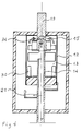
- a pole of a medium or high voltage circuit breaker comprises a sealed enclosure 10, of cylindrical shape inside which an elongated casing 12 is coaxially arranged, confining a breaking chamber 13.
- a pair of contacts, of which one 14 is a movable tubular contact, and the other of which 15 is a fixed tubular contact, extend inside the breaking chamber 13 along the axis of this chamber 13.
- the fixed contact 15 passes through the first bottom 17 of the casing 12, while the movable contact 14 passes through the second bottom 18 of the chamber 13, each of the contacts 14,15 being extended by crossings of the enclosure 10 to connect to connection pads 19 , 20, entry and exit of the pole.
- the tubular contacts 14, 15 have, in the internal part of the enclosure 10, orifices 21 for exhausting the gases making the breaking chamber 13 communicate with the enclosure 10.
- a coil 22 for magnetic arc blowing is coaxially secured to the outside of the fixed contact 15, having opposite the movable contact 14, an electrode 23 of annular shape, for rotation of the root of the arc.
- the coil 22 is arranged in the vicinity of the first bottom 17 of the chamber 13.
- Such a circuit breaker is well known to specialists, and it suffices to recall that when the contacts 14,15 are opened, the arc drawn between these contacts is subjected to the action of the magnetic field, generated by the coil 22, which is crossed by the current, entering at a given time by the track 19, and leaving by the opposite track 20 by crossing the contacts 14,15. Under the action of the arc, the gases contained in the breaking chamber 13 are compressed and escape from the inside of the tubular contacts 14, 15, through orifices 21 towards the expansion enclosure 10.
- the pole may include, as shown schematically in Figure 1, main contacts formed by a movable contact 24 secured to the movable contact 14, and cooperating with the lower edge of the casing 12 of metallic material.
- the metal casing 12 is electrically connected to the input pad 19, and the main contacts 24.25 are arranged, by any suitable means, to separate before the tubular contacts 14.15, acting as arcing contacts.
- In the closed position of the circuit breaker almost all of the current flows through the closed main contacts 24.25.
- the current is switched through the coil 22, and the tubular contacts 14,15, drawing an arc between these contacts as soon as they separate, which follows the separation of the main contacts 24,25.
- the section of the casing 12 is square, and inside this casing 12 is inserted a deflector screen 26, constituted by a cylindrical ferrule disposed at the contact separation zone 14.15.
- the cylindrical ferrule 26 is inscribed in the casing 12, making in the four corners of the passages 27 for communication between a first part 28 of the breaking chamber located on the side of the first bottom 17, and a second part 29 located on the side of the second bottom 18 of the breaking chamber 13.
- the axial height of the cylindrical shell 26 is greater than the distance between the contacts 14,15, and for example close to twice this distance, so as to extend beyond and on the other side of the cut-off zone, to confine the compressed gases.
- the circuit breaker according to the invention operates as follows:
- the arc drawn between the separated contacts 14,15 is subjected to rotation, generated by the coil 22 of magnetic blowing, and it causes on the one hand the heating of the gases present in the cut-off zone, and on the other hand the rotation of these gases.
- These combined effects cause the gases to expand towards the periphery of the interrupting chamber 13, by forming a gas plug in the form of a transverse partition, confined by the cylindrical shell 26.
- This gas plug or partition prevents any flow of gas between the first part 28 of the interrupting chamber, and the second part 29, but this flow can occur in the passages 27 confined between the ferrule 26 and the casing 12.
- the pressure in the first part 28 of the interrupting chamber 13 is generally higher than that of the other part 29 of the chamber. This difference is notably due to the different volume, and the passages 27 allow a transfer of the gases, and therefore the use of the entire volume of the interrupting chamber.
- the second bottom 18 carries fins in the form of plates 30, arranged in the second part 29 of the chamber 13 near the envelope 12.
- These fins 30 brake or prevent the rotation of the gases, and thus deflects the gas flow coming from the passages 27 towards the cutting zone, by promoting the equalization of the pressures inside the chamber 13, and by avoiding the formation of significant depressions due to a vortex effect of the gases, which by decreasing the density in the neighboring area of the contacts 14,15, can be at the origin of reclaquations.
- the shape of the fins 30 and their arrangement inside the chamber 13 can be different, their only purpose being to limit the rotation of the gases inside this chamber.
- Several switching chambers 13 can be accommodated in a common enclosure, in particular three breaking chambers to constitute a three-pole circuit breaker, the square section of these chambers allowing optimal use of the available space.
- the section of the interrupting chamber 13 can be circular, the diameter of the envelope 12 of this chamber 13 being slightly greater than that of the coaxial ferrule 26, so as to provide an annular communication interval, between the first part 28 and the second part 29 of room 13.
- FIG. 3 illustrates an alternative embodiment of the aforementioned type in which the interrupting chamber 13 comprises a cylindrical envelope 12, inside of which is a ferrule 31 of frustoconical shape, the restricted part of which is oriented towards the second bottom 18 of the chamber 13.
- the gap 32 between the wall 12 and the coaxial frusto-conical ferrule 31 is flared downwards and promotes a flow of gases towards the center of the second part 29 of the chamber 13. This arrangement promotes the return of the gas towards the cut-off zone but other arrangements are conceivable.
- the frusto-conical ferrule 31 comprises, opposite the zone of separation of the contacts 14, 15, lights or orifices 33 allowing the passage of the metallic vapors, generated by the action of the arc on the contacts towards the evacuation interval 32 in areas far from the contacts 14.15. This limited exhaust does not disturb the gas flow between the first part 28 of the breaking chamber 13 and the second part 29. It is clear that such lights 33 can also be provided in the shell 26 of the type illustrated in FIG. 1 , or any other similar ferrule.
- the ferrules 26,31 are advantageously metallic as well as the envelopes 12 of square or circular section, but it is clear that it would not go beyond the scope of the present invention, by using ferrules and / or envelopes 12 made of a material insulator in which case, the bottom 17,18, are no longer necessarily made of insulating material.
- the fixed tubular contact 15 is closed at its end and that a lateral orifice 34, close to the closed end, makes the interior of the contact 15 communicate with the breaking chamber 13
- the compressed gas at the periphery of the chamber 13, by the action of the arc, can thus flow back through the tubular contact 15, in the manner indicated by arrows towards the arc zone. This prevents penetration of the arc into the tubular contact.
- This architecture allows the bottom 17 of the chamber 13 to be joined to the bottom of the enclosure 10.
Claims (10)
- Mittelspannungs- oder Hochspannungs-Druckgas-Leistungsschalter mit Drehlichtbogen, der- ein gasdicht verschlossenes, mit einem Gas hoher dielektrischer Festigkeit gefülltes Gehäuse (10),- eine Löschkammer (13) mit einer im genannten Gehäuse (10) angeordneten und an ihren Enden durch eine erste bzw. zweite Bodenplatte (17, 18) abgeschlossenen länglichen Umhüllung (12),- ein in der Löschkammer (13) angeordnetes Kontaktpaar (14, 15), das dazu dient, durch Trennung in der Trennzone der genannten Löschkammer (13) einen Lichtbogen zu ziehen,- eine in der Nähe der genannten ersten Bodenplatte (17) der Löschkammer angeordnete Spule (22) zur magnetischen Beblasung und Drehung des zwischen den Kontakten (14, 15) gezogenen Lichtbogens sowie- mindestens einen in den genannten Kontakten (14, 15) ausgebildeten Strömungskanal umfaßt, der die Löschkammer (13) und das Gehäuse (10) miteinander verbindet und ein Ausströmen der Löschgase von der Löschkammer in das Gehäuse ermöglicht, gekennzeichnet durch eine Abschirmung (26, 31), der in der Nähe der Wand der Umhüllung (12) in Höhe der Trennzone in die genannte Löschkammer (13) eingesetzt ist und die genannte Trennzone koaxial umgibt, um die durch die Wirkung des Lichtbogens verdichteten Gase zu begrenzen, wobei zwischen der Abschirmung (26, 31) und der Umhüllungswand ein Zwischenraum (27, 32) belassen wird, über den ein erster, zwischen der ersten Bodenplatte (17) und der Trennzone angeordneter Bereich (28) und ein zweiter, zwischen der zweiten Bodenplatte (18) und der genannten Trennzone angeordneter Bereich (29) der Löschkammer (13) miteinander verbunden sind, so daß eine Gaszirkulation zwischen dem ersten und dem zweiten Bereich der Löschkammer ermöglicht wird.
- Leistungsschalter nach Anspruch 1, dadurch gekennzeichnet, daß auf der genannten, von der Spule (22) entfernten zweiten Bodenplatte (18) Bremsmittel (30) zur Verlangsamung der Rotation des Lichtbogens angebracht sind, um die Gasströmung in die Trennzone zu begünstigen.
- Leistungsschalter nach Anspruch 1 oder 2, dadurch gekennzeichnet, daß das genannte Kontaktpaar (14, 15) in der Achse der Löschkammer (13) angeordnet und der bewegliche Rohrkontakt (14) als entlang dieser Achse verschiebbarer Gleitkontakt ausgeführt ist und daß die genannte Abschirmung (26, 31) als in der Nähe der Wand der Umhüllung 12 unter Einhaltung des genannten Zwischenraums koaxial um die genannte Achse angeordneter Ring ausgeführt ist.
- Leistungsschalter nach Anspruch 3, dadurch gekennzeichnet, daß die Umhüllung (12) der Löschkammer (13) und der Ring (26, 31) als zylindrische Körper mit koaxial angeordneten Mantelflächen ausgeführt sind, wobei der Durchmesser des Rings etwas kleiner ist als der Durchmesser der Umhüllung, so daß ein ringförmiger Spalt (32) zur Verbindung des genannten ersten und zweiten Bereichs der Löschkammer entsteht.
- Leistungsschalter nach Anspruch 3, dadurch gekennzeichnet, daß der Querschnitt der genannten Umhüllung (12) eine polygonale und der genannte Ring (26) eine in die Umhüllung (12) eingepaßte zylindrische Form aufweisen, so um die genannten Zwischenräume (27) zur Verbindung des ersten Bereichs (28) und des zweiten Bereichs (29) der Löschkammer (13) zu berenzen.
- Leistungsschalter nach Anspruch 3, dadurch gekennzeichnet, daß der genannte Ring (31) eine kegelstumpfartige Mantelfläche aufweist, deren schmalere Seite der genannten zweiten Bodenplatte (18) zugewandt ist.
- Leistungsschalter nach irgendeinem der vorhergehenden Ansprüche, dadurch gekennzeichnet, daß die genannte Abschirmung (26, 31) Aussparungen (33) zur Abführung der Metalldämpfe aus der Trennzone in den genannten Zwischenraum (27, 32) aufweist.
- Leistungsschalter nach irgendeinem der vorhergehenden Ansprüche, dadurch gekennzeichnet, daß die genannte zweite Bodenplatte (18) plattenförmige Stege (30) aufweist, die im genannten zweiten Bereich (29) der Löschkammer (13) längs der inneren Umfangslinie radial angeordnet sind.
- Leistungsschalter nach irgendeinem der vorhergehenden Ansprüche, dadurch gekennzeichnet, daß die zylindrisch geformte Spule (22) mit einem Ende an der genannten ersten Bodenplatte (17) der Umhüllung (12) befestigt ist und daß das gegenüberliegende Ende der Spule eine Ringelektrode (23) trägt, die einen feststehenden Kontakt bildet, der mit einem in der Löschkammer (13) in Axialrichtung gleitend gelagerten beweglichen Rohrkontakt (14) zusammenwirkt.
- Leistungsschalter nach irgendeinem der vorhergehenden Ansprüche, dadurch gekennzeichnet, daß der bewegliche Rohrkontakt eine in das genannte Gehäuse mündende seitliche Durchströmungsöffnung (21) zur Verbindung des Kontakthohlraums mit dem genannten Gehäuse aufweist und daß der feststehende Kontakt rohrförmig ausgeführt ist und eine in die genannte Löschkammer mündende seitliche Durchströmungsöffnung aufweist, um eine Gasströmung durch den Hohlraum des feststehenden Kontakts zu ermöglichen.
Applications Claiming Priority (2)
| Application Number | Priority Date | Filing Date | Title |
|---|---|---|---|
| FR9009938 | 1990-08-01 | ||
| FR9009938A FR2665571B1 (fr) | 1990-08-01 | 1990-08-01 | Disjoncteur electrique a arc tournant et a autoexpansion. |
Publications (2)
| Publication Number | Publication Date |
|---|---|
| EP0470014A1 EP0470014A1 (de) | 1992-02-05 |
| EP0470014B1 true EP0470014B1 (de) | 1994-12-28 |
Family
ID=9399392
Family Applications (1)
| Application Number | Title | Priority Date | Filing Date |
|---|---|---|---|
| EP91420245A Expired - Lifetime EP0470014B1 (de) | 1990-08-01 | 1991-07-12 | Elektrischer Lastschalter mit rotierendem Lichtbogen und Selbstbeblasung |
Country Status (13)
| Country | Link |
|---|---|
| US (1) | US5347097A (de) |
| EP (1) | EP0470014B1 (de) |
| JP (1) | JP3083597B2 (de) |
| KR (1) | KR100204546B1 (de) |
| CN (1) | CN1027841C (de) |
| AU (1) | AU642758B2 (de) |
| BR (1) | BR9103250A (de) |
| CA (1) | CA2047476C (de) |
| DE (1) | DE69106266T2 (de) |
| FR (1) | FR2665571B1 (de) |
| MX (1) | MX9100444A (de) |
| RU (1) | RU2037902C1 (de) |
| ZA (1) | ZA916014B (de) |
Families Citing this family (84)
| Publication number | Priority date | Publication date | Assignee | Title |
|---|---|---|---|---|
| JP3253844B2 (ja) * | 1996-02-09 | 2002-02-04 | 株式会社日立製作所 | ガス遮断器 |
| IT1292453B1 (it) | 1997-07-02 | 1999-02-08 | Aeg Niederspannungstech Gmbh | Gruppo rotante di contatti per interrutttori di alta portata |
| DE19819242B4 (de) | 1998-04-29 | 2005-11-10 | Ge Power Controls Polska Sp.Z.O.O. | Thermomagnetischer Leistungsschalter |
| US6114641A (en) | 1998-05-29 | 2000-09-05 | General Electric Company | Rotary contact assembly for high ampere-rated circuit breakers |
| US6087913A (en) | 1998-11-20 | 2000-07-11 | General Electric Company | Circuit breaker mechanism for a rotary contact system |
| US6037555A (en) | 1999-01-05 | 2000-03-14 | General Electric Company | Rotary contact circuit breaker venting arrangement including current transformer |
| US6166344A (en) | 1999-03-23 | 2000-12-26 | General Electric Company | Circuit breaker handle block |
| US6262872B1 (en) | 1999-06-03 | 2001-07-17 | General Electric Company | Electronic trip unit with user-adjustable sensitivity to current spikes |
| US6268991B1 (en) | 1999-06-25 | 2001-07-31 | General Electric Company | Method and arrangement for customizing electronic circuit interrupters |
| US6218917B1 (en) | 1999-07-02 | 2001-04-17 | General Electric Company | Method and arrangement for calibration of circuit breaker thermal trip unit |
| US6188036B1 (en) | 1999-08-03 | 2001-02-13 | General Electric Company | Bottom vented circuit breaker capable of top down assembly onto equipment |
| US6252365B1 (en) | 1999-08-17 | 2001-06-26 | General Electric Company | Breaker/starter with auto-configurable trip unit |
| US6710988B1 (en) | 1999-08-17 | 2004-03-23 | General Electric Company | Small-sized industrial rated electric motor starter switch unit |
| US6396369B1 (en) | 1999-08-27 | 2002-05-28 | General Electric Company | Rotary contact assembly for high ampere-rated circuit breakers |
| US6175288B1 (en) | 1999-08-27 | 2001-01-16 | General Electric Company | Supplemental trip unit for rotary circuit interrupters |
| US6232570B1 (en) | 1999-09-16 | 2001-05-15 | General Electric Company | Arcing contact arrangement |
| US6326869B1 (en) | 1999-09-23 | 2001-12-04 | General Electric Company | Clapper armature system for a circuit breaker |
| US6239395B1 (en) | 1999-10-14 | 2001-05-29 | General Electric Company | Auxiliary position switch assembly for a circuit breaker |
| US6229413B1 (en) | 1999-10-19 | 2001-05-08 | General Electric Company | Support of stationary conductors for a circuit breaker |
| US6317018B1 (en) | 1999-10-26 | 2001-11-13 | General Electric Company | Circuit breaker mechanism |
| US6232856B1 (en) | 1999-11-02 | 2001-05-15 | General Electric Company | Magnetic shunt assembly |
| US6377144B1 (en) | 1999-11-03 | 2002-04-23 | General Electric Company | Molded case circuit breaker base and mid-cover assembly |
| EP1098343B1 (de) | 1999-11-03 | 2005-09-21 | AEG Niederspannungstechnik GmbH & Co. KG | Drehkontaktanordnung für Schutzschalter |
| US6300586B1 (en) | 1999-12-09 | 2001-10-09 | General Electric Company | Arc runner retaining feature |
| US6310307B1 (en) | 1999-12-17 | 2001-10-30 | General Electric Company | Circuit breaker rotary contact arm arrangement |
| US6172584B1 (en) | 1999-12-20 | 2001-01-09 | General Electric Company | Circuit breaker accessory reset system |
| US6184761B1 (en) | 1999-12-20 | 2001-02-06 | General Electric Company | Circuit breaker rotary contact arrangement |
| US6215379B1 (en) | 1999-12-23 | 2001-04-10 | General Electric Company | Shunt for indirectly heated bimetallic strip |
| US6281461B1 (en) | 1999-12-27 | 2001-08-28 | General Electric Company | Circuit breaker rotor assembly having arc prevention structure |
| US6346869B1 (en) | 1999-12-28 | 2002-02-12 | General Electric Company | Rating plug for circuit breakers |
| US6211758B1 (en) | 2000-01-11 | 2001-04-03 | General Electric Company | Circuit breaker accessory gap control mechanism |
| US6239677B1 (en) | 2000-02-10 | 2001-05-29 | General Electric Company | Circuit breaker thermal magnetic trip unit |
| US6429759B1 (en) | 2000-02-14 | 2002-08-06 | General Electric Company | Split and angled contacts |
| US6313425B1 (en) | 2000-02-24 | 2001-11-06 | General Electric Company | Cassette assembly with rejection features |
| US6281458B1 (en) | 2000-02-24 | 2001-08-28 | General Electric Company | Circuit breaker auxiliary magnetic trip unit with pressure sensitive release |
| US6204743B1 (en) | 2000-02-29 | 2001-03-20 | General Electric Company | Dual connector strap for a rotary contact circuit breaker |
| US6404314B1 (en) | 2000-02-29 | 2002-06-11 | General Electric Company | Adjustable trip solenoid |
| US6346868B1 (en) | 2000-03-01 | 2002-02-12 | General Electric Company | Circuit interrupter operating mechanism |
| US6379196B1 (en) | 2000-03-01 | 2002-04-30 | General Electric Company | Terminal connector for a circuit breaker |
| US6340925B1 (en) | 2000-03-01 | 2002-01-22 | General Electric Company | Circuit breaker mechanism tripping cam |
| US6448521B1 (en) | 2000-03-01 | 2002-09-10 | General Electric Company | Blocking apparatus for circuit breaker contact structure |
| US6459349B1 (en) | 2000-03-06 | 2002-10-01 | General Electric Company | Circuit breaker comprising a current transformer with a partial air gap |
| US6211757B1 (en) | 2000-03-06 | 2001-04-03 | General Electric Company | Fast acting high force trip actuator |
| US6366438B1 (en) | 2000-03-06 | 2002-04-02 | General Electric Company | Circuit interrupter rotary contact arm |
| US6496347B1 (en) | 2000-03-08 | 2002-12-17 | General Electric Company | System and method for optimization of a circuit breaker mechanism |
| US6429659B1 (en) | 2000-03-09 | 2002-08-06 | General Electric Company | Connection tester for an electronic trip unit |
| US6366188B1 (en) | 2000-03-15 | 2002-04-02 | General Electric Company | Accessory and recess identification system for circuit breakers |
| US6232859B1 (en) | 2000-03-15 | 2001-05-15 | General Electric Company | Auxiliary switch mounting configuration for use in a molded case circuit breaker |
| US6218919B1 (en) | 2000-03-15 | 2001-04-17 | General Electric Company | Circuit breaker latch mechanism with decreased trip time |
| US6459059B1 (en) | 2000-03-16 | 2002-10-01 | General Electric Company | Return spring for a circuit interrupter operating mechanism |
| US6421217B1 (en) | 2000-03-16 | 2002-07-16 | General Electric Company | Circuit breaker accessory reset system |
| US6472620B2 (en) | 2000-03-17 | 2002-10-29 | Ge Power Controls France Sas | Locking arrangement for circuit breaker draw-out mechanism |
| US6639168B1 (en) | 2000-03-17 | 2003-10-28 | General Electric Company | Energy absorbing contact arm stop |
| US6388213B1 (en) | 2000-03-17 | 2002-05-14 | General Electric Company | Locking device for molded case circuit breakers |
| US6476698B1 (en) | 2000-03-17 | 2002-11-05 | General Electric Company | Convertible locking arrangement on breakers |
| US6479774B1 (en) | 2000-03-17 | 2002-11-12 | General Electric Company | High energy closing mechanism for circuit breakers |
| US6559743B2 (en) | 2000-03-17 | 2003-05-06 | General Electric Company | Stored energy system for breaker operating mechanism |
| US6373010B1 (en) | 2000-03-17 | 2002-04-16 | General Electric Company | Adjustable energy storage mechanism for a circuit breaker motor operator |
| FR2806548B1 (fr) | 2000-03-17 | 2002-08-23 | Ge Power Controls France | Mecanisme extractible pour disjoncteurs |
| US6586693B2 (en) | 2000-03-17 | 2003-07-01 | General Electric Company | Self compensating latch arrangement |
| US6747535B2 (en) | 2000-03-27 | 2004-06-08 | General Electric Company | Precision location system between actuator accessory and mechanism |
| US6373357B1 (en) | 2000-05-16 | 2002-04-16 | General Electric Company | Pressure sensitive trip mechanism for a rotary breaker |
| US6995640B2 (en) | 2000-05-16 | 2006-02-07 | General Electric Company | Pressure sensitive trip mechanism for circuit breakers |
| US6400245B1 (en) | 2000-10-13 | 2002-06-04 | General Electric Company | Draw out interlock for circuit breakers |
| US6429760B1 (en) | 2000-10-19 | 2002-08-06 | General Electric Company | Cross bar for a conductor in a rotary breaker |
| US6531941B1 (en) | 2000-10-19 | 2003-03-11 | General Electric Company | Clip for a conductor in a rotary breaker |
| US6806800B1 (en) | 2000-10-19 | 2004-10-19 | General Electric Company | Assembly for mounting a motor operator on a circuit breaker |
| US6362711B1 (en) | 2000-11-10 | 2002-03-26 | General Electric Company | Circuit breaker cover with screw locating feature |
| US6380829B1 (en) | 2000-11-21 | 2002-04-30 | General Electric Company | Motor operator interlock and method for circuit breakers |
| US6448522B1 (en) | 2001-01-30 | 2002-09-10 | General Electric Company | Compact high speed motor operator for a circuit breaker |
| US6476337B2 (en) | 2001-02-26 | 2002-11-05 | General Electric Company | Auxiliary switch actuation arrangement |
| US6678135B2 (en) | 2001-09-12 | 2004-01-13 | General Electric Company | Module plug for an electronic trip unit |
| US6469882B1 (en) | 2001-10-31 | 2002-10-22 | General Electric Company | Current transformer initial condition correction |
| US6804101B2 (en) | 2001-11-06 | 2004-10-12 | General Electric Company | Digital rating plug for electronic trip unit in circuit breakers |
| KR100658182B1 (ko) * | 2005-12-30 | 2006-12-15 | 엘에스산전 주식회사 | 회로 차단기 |
| CN102254758B (zh) * | 2011-07-28 | 2014-05-14 | 苏州鼎能电力设备有限公司 | 应用于断路器中的灭弧室 |
| FR3005781B1 (fr) * | 2013-05-17 | 2016-09-23 | Schneider Electric Ind Sas | Chambre de coupure pour un appareil de protection electrique et appareil de protection electrique la comportant. |
| FR3007889B1 (fr) * | 2013-06-26 | 2016-09-23 | Schneider Electric Ind Sas | Chambre de coupure pour un appareil de protection electrique et appareil de protection electrique comportant une telle chambre. |
| US9355798B2 (en) | 2014-08-21 | 2016-05-31 | General Electric Company | System and method for quenching an arc |
| CN107731616A (zh) * | 2017-11-16 | 2018-02-23 | 中国科学院电工研究所 | 平行串联多断口灭弧室 |
| RU186667U1 (ru) * | 2018-08-27 | 2019-01-29 | Закрытое акционерное общество "Завод электротехнического оборудования" (ЗАО "ЗЭТО") | Выключатель с газовой изоляцией |
| RU2749031C1 (ru) * | 2020-07-24 | 2021-06-03 | Валерий Александрович Лавринович | Экранная система для высоковольтной вакуумной дугогасительной камеры |
| CN113161192B (zh) * | 2021-04-22 | 2023-01-20 | 云南电网有限责任公司电力科学研究院 | 一种磁场增强型的真空断路器 |
| CN116994912B (zh) * | 2023-09-25 | 2023-12-22 | 新乡市镇华电力科技有限公司 | 一种户内高压真空断路器 |
Family Cites Families (8)
| Publication number | Priority date | Publication date | Assignee | Title |
|---|---|---|---|---|
| CH320907A (fr) * | 1954-11-11 | 1957-04-15 | Gardy Particip App | Disjoncteur à liquide extincteur |
| US4095068A (en) * | 1976-05-12 | 1978-06-13 | Westinghouse Electric Corp. | Stationary-contact-and voltage-shield assembly for a gas-puffer-type circuit-interrupter |
| FR2441261A1 (fr) * | 1978-11-10 | 1980-06-06 | Merlin Gerin | Interrupteur a arc tournant |
| JPS59144726U (ja) * | 1983-03-15 | 1984-09-27 | 日新電機株式会社 | ガスしや断器 |
| DE3538955A1 (de) * | 1985-10-29 | 1987-05-07 | Siemens Ag | Druckgasschalter |
| FR2623657A1 (fr) * | 1987-11-19 | 1989-05-26 | Merlin Gerin | Disjoncteur a autosoufflage par expansion de gaz isolant, equipe d'un ecran de repartition de champ electrique |
| ES2066175T3 (es) * | 1989-02-27 | 1995-03-01 | Merlin Gerin | Disyuntor de arco giratorio y con efecto centrifugo del gas de extincion. |
| FR2663457B1 (fr) * | 1990-06-14 | 1996-06-07 | Merlin Gerin | Disjoncteur electrique a autoexpansion et a rotation de l'arc. |
-
1990
- 1990-08-01 FR FR9009938A patent/FR2665571B1/fr not_active Expired - Fee Related
-
1991
- 1991-07-12 EP EP91420245A patent/EP0470014B1/de not_active Expired - Lifetime
- 1991-07-12 DE DE69106266T patent/DE69106266T2/de not_active Expired - Fee Related
- 1991-07-19 CA CA002047476A patent/CA2047476C/en not_active Expired - Fee Related
- 1991-07-30 MX MX9100444A patent/MX9100444A/es not_active IP Right Cessation
- 1991-07-30 BR BR919103250A patent/BR9103250A/pt not_active IP Right Cessation
- 1991-07-31 AU AU81465/91A patent/AU642758B2/en not_active Ceased
- 1991-07-31 RU SU915001232A patent/RU2037902C1/ru active
- 1991-07-31 ZA ZA916014A patent/ZA916014B/xx unknown
- 1991-07-31 CN CN91105235A patent/CN1027841C/zh not_active Expired - Fee Related
- 1991-07-31 JP JP03214822A patent/JP3083597B2/ja not_active Expired - Fee Related
- 1991-08-01 KR KR1019910013345A patent/KR100204546B1/ko not_active IP Right Cessation
-
1993
- 1993-08-02 US US08/101,279 patent/US5347097A/en not_active Expired - Fee Related
Also Published As
| Publication number | Publication date |
|---|---|
| AU8146591A (en) | 1992-02-06 |
| CN1058671A (zh) | 1992-02-12 |
| KR920005203A (ko) | 1992-03-28 |
| JPH04253129A (ja) | 1992-09-08 |
| BR9103250A (pt) | 1992-05-26 |
| CN1027841C (zh) | 1995-03-08 |
| AU642758B2 (en) | 1993-10-28 |
| ZA916014B (en) | 1992-04-29 |
| EP0470014A1 (de) | 1992-02-05 |
| MX9100444A (es) | 1992-04-01 |
| JP3083597B2 (ja) | 2000-09-04 |
| KR100204546B1 (ko) | 1999-06-15 |
| US5347097A (en) | 1994-09-13 |
| FR2665571A1 (fr) | 1992-02-07 |
| DE69106266T2 (de) | 1995-06-29 |
| FR2665571B1 (fr) | 1992-10-16 |
| RU2037902C1 (ru) | 1995-06-19 |
| DE69106266D1 (de) | 1995-02-09 |
| CA2047476C (en) | 2000-09-12 |
| CA2047476A1 (en) | 1992-02-02 |
Similar Documents
| Publication | Publication Date | Title |
|---|---|---|
| EP0470014B1 (de) | Elektrischer Lastschalter mit rotierendem Lichtbogen und Selbstbeblasung | |
| EP0385886B1 (de) | Lastschalter mit rotierendem Lichtbogen und mit Zentrifugal-Effekt des Löschgases | |
| EP0538157B1 (de) | Hybridschalter mit Axialblasspule | |
| EP0388323B1 (de) | Elektrischer Autoexpansionsschalter mit Isoliergas | |
| EP2593954B1 (de) | Trennkammeranlage für zwei elektroden mit begrenzten kontakt | |
| EP0179834B1 (de) | Schaltvorrichtung mit trennwand zum unterbrechen des lichtbogens | |
| FR2476381A1 (fr) | Sectionneur isole par gaz | |
| EP0240397A1 (de) | Selbstbeblasender elektrischer Lastschalter mit rotierendem Lichtbogen | |
| CA1239432A (fr) | Dispositif d'extinction d'arc pour appareillage electrique a isolement gazeux | |
| EP0149470A2 (de) | Hochspannungsschalter mit Lichtbogenbeblasung | |
| FR2576144A1 (fr) | Disjoncteur a haute tension, a gaz comprime, a faible energie de manoeuvre | |
| EP0004213B1 (de) | Lichtbogenlöscheinrichtung mit pneumatischer und magnetischer Blasung | |
| EP1612823B1 (de) | Passive Kühlvorrichtung für ein elektrisches Gerät und elektrisches Gerät mit einer solchen Vorrichtung | |
| CA2023525C (fr) | Disjoncteur a moyenne tension autosoufflage | |
| EP0079293B1 (de) | Modulschalter mit magnetischem Blasfluss und mit Gaskühlung | |
| FR2490397A2 (fr) | Disjoncteur a haute tension a arc tournant et autosoufflage | |
| FR2575323A1 (fr) | Disjoncteur a gaz comprime | |
| FR2479553A1 (fr) | Interrupteur a arc tournant et a expansion thermique du gaz de soufflage | |
| EP0101371B1 (de) | Elektrischer Schalter mit rotierendem Lichtbogen | |
| FR2623657A1 (fr) | Disjoncteur a autosoufflage par expansion de gaz isolant, equipe d'un ecran de repartition de champ electrique | |
| CH634687A5 (en) | Rotating-arc and self-blasting high-voltage circuit breaker | |
| EP0526296B1 (de) | Druckgasschalter für Hoch- und Mittelspannung | |
| EP0045229B1 (de) | Schalter mit doppelt rotierendem Lichtbogen | |
| EP0078719A1 (de) | Selbstblasschalter mit Dauermagnet | |
| FR2563372A1 (fr) | Disjoncteur haute tension a soufflage d'arc |
Legal Events
| Date | Code | Title | Description |
|---|---|---|---|
| PUAI | Public reference made under article 153(3) epc to a published international application that has entered the european phase |
Free format text: ORIGINAL CODE: 0009012 |
|
| AK | Designated contracting states |
Kind code of ref document: A1 Designated state(s): BE CH DE ES FR GB IT LI SE |
|
| 17P | Request for examination filed |
Effective date: 19920707 |
|
| 17Q | First examination report despatched |
Effective date: 19940314 |
|
| GRAA | (expected) grant |
Free format text: ORIGINAL CODE: 0009210 |
|
| AK | Designated contracting states |
Kind code of ref document: B1 Designated state(s): BE CH DE ES FR GB IT LI SE |
|
| PG25 | Lapsed in a contracting state [announced via postgrant information from national office to epo] |
Ref country code: IT Free format text: LAPSE BECAUSE OF FAILURE TO SUBMIT A TRANSLATION OF THE DESCRIPTION OR TO PAY THE FEE WITHIN THE PRE;WARNING: LAPSES OF ITALIAN PATENTS WITH EFFECTIVE DATE BEFORE 2007 MAY HAVE OCCURRED AT ANY TIME BEFORE 2007. THE CORRECT EFFECTIVE DATE MAY BE DIFFERENT FROM THE ONE RECORDED.SCRIBED TIME-LIMIT Effective date: 19941228 Ref country code: ES Free format text: THE PATENT HAS BEEN ANNULLED BY A DECISION OF A NATIONAL AUTHORITY Effective date: 19941228 Ref country code: GB Effective date: 19941228 |
|
| REF | Corresponds to: |
Ref document number: 69106266 Country of ref document: DE Date of ref document: 19950209 |
|
| PG25 | Lapsed in a contracting state [announced via postgrant information from national office to epo] |
Ref country code: SE Effective date: 19950328 |
|
| GBV | Gb: ep patent (uk) treated as always having been void in accordance with gb section 77(7)/1977 [no translation filed] |
Effective date: 19941228 |
|
| PG25 | Lapsed in a contracting state [announced via postgrant information from national office to epo] |
Ref country code: LI Effective date: 19950731 Ref country code: BE Effective date: 19950731 Ref country code: CH Effective date: 19950731 |
|
| PLBE | No opposition filed within time limit |
Free format text: ORIGINAL CODE: 0009261 |
|
| STAA | Information on the status of an ep patent application or granted ep patent |
Free format text: STATUS: NO OPPOSITION FILED WITHIN TIME LIMIT |
|
| 26N | No opposition filed | ||
| BERE | Be: lapsed |
Owner name: MERLIN GERIN Effective date: 19950731 |
|
| REG | Reference to a national code |
Ref country code: CH Ref legal event code: PL |
|
| PGFP | Annual fee paid to national office [announced via postgrant information from national office to epo] |
Ref country code: FR Payment date: 20040704 Year of fee payment: 14 |
|
| PGFP | Annual fee paid to national office [announced via postgrant information from national office to epo] |
Ref country code: DE Payment date: 20040709 Year of fee payment: 14 |
|
| PG25 | Lapsed in a contracting state [announced via postgrant information from national office to epo] |
Ref country code: DE Free format text: LAPSE BECAUSE OF NON-PAYMENT OF DUE FEES Effective date: 20060201 |
|
| PG25 | Lapsed in a contracting state [announced via postgrant information from national office to epo] |
Ref country code: FR Free format text: LAPSE BECAUSE OF NON-PAYMENT OF DUE FEES Effective date: 20060331 |
|
| REG | Reference to a national code |
Ref country code: FR Ref legal event code: ST Effective date: 20060331 |