EP0470014B1 - Electrical circuit breaker with rotating arc and self blast mechanism - Google Patents
Electrical circuit breaker with rotating arc and self blast mechanism Download PDFInfo
- Publication number
- EP0470014B1 EP0470014B1 EP91420245A EP91420245A EP0470014B1 EP 0470014 B1 EP0470014 B1 EP 0470014B1 EP 91420245 A EP91420245 A EP 91420245A EP 91420245 A EP91420245 A EP 91420245A EP 0470014 B1 EP0470014 B1 EP 0470014B1
- Authority
- EP
- European Patent Office
- Prior art keywords
- chamber
- circuit breaker
- electrical circuit
- extinguishing
- arc
- Prior art date
- Legal status (The legal status is an assumption and is not a legal conclusion. Google has not performed a legal analysis and makes no representation as to the accuracy of the status listed.)
- Expired - Lifetime
Links
Images


Classifications
-
- H—ELECTRICITY
- H01—ELECTRIC ELEMENTS
- H01H—ELECTRIC SWITCHES; RELAYS; SELECTORS; EMERGENCY PROTECTIVE DEVICES
- H01H33/00—High-tension or heavy-current switches with arc-extinguishing or arc-preventing means
- H01H33/70—Switches with separate means for directing, obtaining, or increasing flow of arc-extinguishing fluid
- H01H33/72—Switches with separate means for directing, obtaining, or increasing flow of arc-extinguishing fluid having stationary parts for directing the flow of arc-extinguishing fluid, e.g. arc-extinguishing chamber
- H01H33/74—Switches with separate means for directing, obtaining, or increasing flow of arc-extinguishing fluid having stationary parts for directing the flow of arc-extinguishing fluid, e.g. arc-extinguishing chamber wherein the break is in gas
-
- H—ELECTRICITY
- H01—ELECTRIC ELEMENTS
- H01H—ELECTRIC SWITCHES; RELAYS; SELECTORS; EMERGENCY PROTECTIVE DEVICES
- H01H33/00—High-tension or heavy-current switches with arc-extinguishing or arc-preventing means
- H01H33/70—Switches with separate means for directing, obtaining, or increasing flow of arc-extinguishing fluid
- H01H33/7015—Switches with separate means for directing, obtaining, or increasing flow of arc-extinguishing fluid characterised by flow directing elements associated with contacts
- H01H33/7038—Switches with separate means for directing, obtaining, or increasing flow of arc-extinguishing fluid characterised by flow directing elements associated with contacts characterised by a conducting tubular gas flow enhancing nozzle
-
- H—ELECTRICITY
- H01—ELECTRIC ELEMENTS
- H01H—ELECTRIC SWITCHES; RELAYS; SELECTORS; EMERGENCY PROTECTIVE DEVICES
- H01H33/00—High-tension or heavy-current switches with arc-extinguishing or arc-preventing means
- H01H33/70—Switches with separate means for directing, obtaining, or increasing flow of arc-extinguishing fluid
- H01H33/98—Switches with separate means for directing, obtaining, or increasing flow of arc-extinguishing fluid the flow of arc-extinguishing fluid being initiated by an auxiliary arc or a section of the arc, without any moving parts for producing or increasing the flow
- H01H33/982—Switches with separate means for directing, obtaining, or increasing flow of arc-extinguishing fluid the flow of arc-extinguishing fluid being initiated by an auxiliary arc or a section of the arc, without any moving parts for producing or increasing the flow in which the pressure-generating arc is rotated by a magnetic field
Definitions
- the arc is blown by the gas flow between the breaking chamber and the external expansion enclosure, through the generally shaped contacts tubular.
- the efficiency of this pneumatic blowing is a function of the volume of the breaking chamber which can be important for high voltage circuit breakers, and also of the optimal use of this volume.
- deflectors or screens inside the interrupting chamber, the purpose of which is to guide the gas flow in order to direct it towards the flow conduits inside. contacts, either to slow the rotation of gases and avoid areas of overpressure and depression, which may affect the dielectric strength in sensitive areas.
- the present invention starts from the observation that the gases subjected in the cut-off zone to the action of the arc, are compressed and driven in rotation, which causes an expansion forming a gas plug extending to the wall of the room, by dividing the latter into two parts.
- This gas plug or partition prevents any circulation of gases from one part of the chamber to the other, and is at the origin of a partial use of the volume of the breaking chamber.
- the present invention aims to increase the performance of the circuit breaker, by promoting the exchange of gas between the two parts of the chamber, despite the presence of this plug disposed at the breaking zone.
- the electric circuit breaker according to the invention is characterized by a deflector screen, arranged in said chamber near the wall of the enclosure at the cut-off zone and coaxially surrounding said cut-off zone, so as to confine the compressed gases by the action of the arc, leaving a gap between the screen and the wall, which communicates a first part of the chamber, located between the first bottom, and the cutting zone with a second part of the chamber , located between the second bottom and said cut-off zone, allowing gas circulation between the first and second part of the chamber.
- the deflector screen limits the expansion of the gas plug, and preserves communication passages between the two parts of the chamber, located on either side of this gas plug.
- the gas flow takes place from the first part of the chamber arranged on the side of the coil and having a smaller volume towards the second part of the chamber located on the side of the movable contact.
- this gas exchange is increased by an orientation of the gases towards the breaking zone, this gas return being obtained by fixed fins, carried by the bottom of the chamber on the side of the movable contact, which brake or prevent the rotation of the gases.
- the gases are no longer subjected to centrifugal force, and can thus return to the central part, where they flow through the tubular contacts towards the expansion enclosure.
- An efficient blowing is thus obtained by using the entire volume of the interrupting chamber, and by avoiding any depression in the contact zone, likely to generate priming or reclacing.
- the pair of contacts is arranged on the axis of the interrupting chamber, of elongated shape, and one of the tubular contacts is mounted to slide along this axis.
- the deflector screen in the form of a ferrule, for example cylindrical, extends close to the wall of the chamber, and coaxially frames the breaking zone defined by the separation interval of the contacts in the open position.
- the ferrule or cylindrical surface may be of a slightly smaller diameter of the envelope of the chamber, also of cylindrical shape, so as to provide an annular communication gap between the two parts of the chamber, situated on either side of this cylindrical shell.
- the ferrule can also be frustoconical, the reduced section then being oriented towards the moving contact side of the circuit breaker.
- the ferrule is cylindrical, and is inserted in a polygonal envelope, for example square, which marries without play and externally the cylindrical ferrule.
- the communication passages between the two parts of the chamber are arranged at the corners of the envelope, which are spaced from the cylindrical shell.
- Other embodiments can be used, in particular ferrules of polygonal section, inserted in cylindrical envelopes or not, the important point being the presence of intervals between the ferrule and the envelope, extending along the internal periphery of the envelope for communicating the two parts of the chamber, located on either side of the cutting zone.
- the height of the ferrule which corresponds to the axial direction of the latter, is preferably greater than the separation distance of the contacts, in the open position, so as to overflow on either side of the breaking zone.
- This height can in particular be close to twice this separation distance, so as to effectively confine the gases which are expanding under the action of the arc, towards the wall of the envelope.
- the ferrule advantageously comprises, opposite the cut-off zone, lights or holes allowing the passage of metallic vapors towards the wall of the envelope where they are entrained in a zone remote from the cut-off zone.
- the number or dimensions of the fins carried by the bottom are sufficient to impede the rotation of the gases, and these fins, preferably in the form of plates, extend in radial planes, remaining in the vicinity of the internal face of the envelope. .
- the blowing coil of cylindrical shape, is associated with the fixed contact, preferably tubular, the two contacts passing through a sealed manner, respectively the two bottoms of the chamber to make the latter communicate with the expansion enclosure, which can be individual for each pole or be common to the three poles of the circuit breaker. In the latter case, the square section of the room allows maximum use of the available volumes.
- the fixed contact is tubular and the internal conduit to the contact communicates through a lateral orifice with the breaking chamber.
- the bottom of the chamber can then be close to or be attached to the bottom of the enclosure and the height of the enclosure is reduced accordingly.
- the gas compressed by the action of the arc circulates inside the fixed contact and avoids a depression likely to draw the arc inside the contact.
- the orifice is close to the bottom of the chamber, on the side of the coil opposite the cut-off zone.
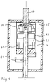
- a pole of a medium or high voltage circuit breaker comprises a sealed enclosure 10, of cylindrical shape inside which an elongated casing 12 is coaxially arranged, confining a breaking chamber 13.
- a pair of contacts, of which one 14 is a movable tubular contact, and the other of which 15 is a fixed tubular contact, extend inside the breaking chamber 13 along the axis of this chamber 13.
- the fixed contact 15 passes through the first bottom 17 of the casing 12, while the movable contact 14 passes through the second bottom 18 of the chamber 13, each of the contacts 14,15 being extended by crossings of the enclosure 10 to connect to connection pads 19 , 20, entry and exit of the pole.
- the tubular contacts 14, 15 have, in the internal part of the enclosure 10, orifices 21 for exhausting the gases making the breaking chamber 13 communicate with the enclosure 10.
- a coil 22 for magnetic arc blowing is coaxially secured to the outside of the fixed contact 15, having opposite the movable contact 14, an electrode 23 of annular shape, for rotation of the root of the arc.
- the coil 22 is arranged in the vicinity of the first bottom 17 of the chamber 13.
- Such a circuit breaker is well known to specialists, and it suffices to recall that when the contacts 14,15 are opened, the arc drawn between these contacts is subjected to the action of the magnetic field, generated by the coil 22, which is crossed by the current, entering at a given time by the track 19, and leaving by the opposite track 20 by crossing the contacts 14,15. Under the action of the arc, the gases contained in the breaking chamber 13 are compressed and escape from the inside of the tubular contacts 14, 15, through orifices 21 towards the expansion enclosure 10.
- the pole may include, as shown schematically in Figure 1, main contacts formed by a movable contact 24 secured to the movable contact 14, and cooperating with the lower edge of the casing 12 of metallic material.
- the metal casing 12 is electrically connected to the input pad 19, and the main contacts 24.25 are arranged, by any suitable means, to separate before the tubular contacts 14.15, acting as arcing contacts.
- In the closed position of the circuit breaker almost all of the current flows through the closed main contacts 24.25.
- the current is switched through the coil 22, and the tubular contacts 14,15, drawing an arc between these contacts as soon as they separate, which follows the separation of the main contacts 24,25.
- the section of the casing 12 is square, and inside this casing 12 is inserted a deflector screen 26, constituted by a cylindrical ferrule disposed at the contact separation zone 14.15.
- the cylindrical ferrule 26 is inscribed in the casing 12, making in the four corners of the passages 27 for communication between a first part 28 of the breaking chamber located on the side of the first bottom 17, and a second part 29 located on the side of the second bottom 18 of the breaking chamber 13.
- the axial height of the cylindrical shell 26 is greater than the distance between the contacts 14,15, and for example close to twice this distance, so as to extend beyond and on the other side of the cut-off zone, to confine the compressed gases.
- the circuit breaker according to the invention operates as follows:
- the arc drawn between the separated contacts 14,15 is subjected to rotation, generated by the coil 22 of magnetic blowing, and it causes on the one hand the heating of the gases present in the cut-off zone, and on the other hand the rotation of these gases.
- These combined effects cause the gases to expand towards the periphery of the interrupting chamber 13, by forming a gas plug in the form of a transverse partition, confined by the cylindrical shell 26.
- This gas plug or partition prevents any flow of gas between the first part 28 of the interrupting chamber, and the second part 29, but this flow can occur in the passages 27 confined between the ferrule 26 and the casing 12.
- the pressure in the first part 28 of the interrupting chamber 13 is generally higher than that of the other part 29 of the chamber. This difference is notably due to the different volume, and the passages 27 allow a transfer of the gases, and therefore the use of the entire volume of the interrupting chamber.
- the second bottom 18 carries fins in the form of plates 30, arranged in the second part 29 of the chamber 13 near the envelope 12.
- These fins 30 brake or prevent the rotation of the gases, and thus deflects the gas flow coming from the passages 27 towards the cutting zone, by promoting the equalization of the pressures inside the chamber 13, and by avoiding the formation of significant depressions due to a vortex effect of the gases, which by decreasing the density in the neighboring area of the contacts 14,15, can be at the origin of reclaquations.
- the shape of the fins 30 and their arrangement inside the chamber 13 can be different, their only purpose being to limit the rotation of the gases inside this chamber.
- Several switching chambers 13 can be accommodated in a common enclosure, in particular three breaking chambers to constitute a three-pole circuit breaker, the square section of these chambers allowing optimal use of the available space.
- the section of the interrupting chamber 13 can be circular, the diameter of the envelope 12 of this chamber 13 being slightly greater than that of the coaxial ferrule 26, so as to provide an annular communication interval, between the first part 28 and the second part 29 of room 13.
- FIG. 3 illustrates an alternative embodiment of the aforementioned type in which the interrupting chamber 13 comprises a cylindrical envelope 12, inside of which is a ferrule 31 of frustoconical shape, the restricted part of which is oriented towards the second bottom 18 of the chamber 13.
- the gap 32 between the wall 12 and the coaxial frusto-conical ferrule 31 is flared downwards and promotes a flow of gases towards the center of the second part 29 of the chamber 13. This arrangement promotes the return of the gas towards the cut-off zone but other arrangements are conceivable.
- the frusto-conical ferrule 31 comprises, opposite the zone of separation of the contacts 14, 15, lights or orifices 33 allowing the passage of the metallic vapors, generated by the action of the arc on the contacts towards the evacuation interval 32 in areas far from the contacts 14.15. This limited exhaust does not disturb the gas flow between the first part 28 of the breaking chamber 13 and the second part 29. It is clear that such lights 33 can also be provided in the shell 26 of the type illustrated in FIG. 1 , or any other similar ferrule.
- the ferrules 26,31 are advantageously metallic as well as the envelopes 12 of square or circular section, but it is clear that it would not go beyond the scope of the present invention, by using ferrules and / or envelopes 12 made of a material insulator in which case, the bottom 17,18, are no longer necessarily made of insulating material.
- the fixed tubular contact 15 is closed at its end and that a lateral orifice 34, close to the closed end, makes the interior of the contact 15 communicate with the breaking chamber 13
- the compressed gas at the periphery of the chamber 13, by the action of the arc, can thus flow back through the tubular contact 15, in the manner indicated by arrows towards the arc zone. This prevents penetration of the arc into the tubular contact.
- This architecture allows the bottom 17 of the chamber 13 to be joined to the bottom of the enclosure 10.
Landscapes
- Arc-Extinguishing Devices That Are Switches (AREA)
- Circuit Breakers (AREA)
- Breakers (AREA)
Description
L'invention est relative à un disjoncteur électrique moyenne ou haute tension à arc tournant et à autoexpansion comprenant:
- une enceinte étanche remplie d'un gaz à rigidité diélectrique élevée,
- une chambre de coupure ayant une enveloppe allongée disposée dans ladite enceinte, et obturée à ses extrémités respectivement par un premier et un deuxième fond,
- une paire de contacts logés dans la chambre de coupure et susceptibles d'être séparés pour tirer un arc dans la zone de coupure de ladite chambre,
- une bobine de soufflage magnétique en rotation de l'arc tiré entre les contacts, disposée au voisinage dudit premier fond de la chambre,
- au moins un conduit ménagé dans lesdits contacts pour faire communiquer la chambre de coupure et l'enceinte, et autoriser un échappement des gaz de coupure de la chambre vers l'enceinte.
- a sealed enclosure filled with a gas with high dielectric strength,
- a breaking chamber having an elongated envelope disposed in said enclosure, and closed at its ends respectively by a first and a second bottom,
- a pair of contacts housed in the breaking chamber and capable of being separated to draw an arc in the breaking zone of said chamber,
- a magnetic blowing coil in rotation of the arc drawn between the contacts, arranged in the vicinity of said first bottom of the chamber,
- at least one conduit formed in said contacts for communicating the interrupting chamber and the enclosure, and authorizing an escape of the interrupting gases from the chamber towards the enclosure.
Dans un disjoncteur du genre mentionné (voir par exemple FR-A-2 623 657), l'arc est soufflé par l'écoulement gazeux entre la chambre de coupure et l'enceinte externe d'expansion, à travers les contacts généralement de forme tubulaire. L'efficacité de ce soufflage pneumatique est fonction du volume de la chambre de coupure qui peut être important pour des disjoncteurs haute tension, et également de l'utilisation optimale de ce volume. A cet effet il a déjà été proposé, de disposer à l'intérieur de la chambre de coupure, des déflecteurs ou écrans ayant pour but, soit de guider l'écoulement gazeux pour l'orienter vers les conduits d'écoulement à l'intérieur des contacts, soit pour freiner la rotation des gaz et éviter des zones de surpression et de dépression, susceptibles d'affecter la rigidité diélectrique dans les zones sensibles.In a circuit breaker of the type mentioned (see for example FR-A-2 623 657), the arc is blown by the gas flow between the breaking chamber and the external expansion enclosure, through the generally shaped contacts tubular. The efficiency of this pneumatic blowing is a function of the volume of the breaking chamber which can be important for high voltage circuit breakers, and also of the optimal use of this volume. To this end, it has already been proposed to have deflectors or screens inside the interrupting chamber, the purpose of which is to guide the gas flow in order to direct it towards the flow conduits inside. contacts, either to slow the rotation of gases and avoid areas of overpressure and depression, which may affect the dielectric strength in sensitive areas.
La présente invention part de la constatation que les gaz soumis dans la zone de coupure à l'action de l'arc, sont comprimés et entraînés en rotation, ce qui provoque une expansion formant un bouchon gazeux s'étendant jusqu'à la paroi de la chambre, en cloisonnant cette dernière en deux parties. Ce bouchon gazeux ou cloison empêche toute circulation des gaz d'une partie de la chambre vers l'autre, et est à l'origine d'une utilisation partielle du volume de la chambre de coupure.The present invention starts from the observation that the gases subjected in the cut-off zone to the action of the arc, are compressed and driven in rotation, which causes an expansion forming a gas plug extending to the wall of the room, by dividing the latter into two parts. This gas plug or partition prevents any circulation of gases from one part of the chamber to the other, and is at the origin of a partial use of the volume of the breaking chamber.
La présente invention a pour but d'accroître les performances du disjoncteur, en favorisant l'échange de gaz entre les deux parties de la chambre, en dépit de la présence de ce bouchon disposé au niveau de la zone de coupure.The present invention aims to increase the performance of the circuit breaker, by promoting the exchange of gas between the two parts of the chamber, despite the presence of this plug disposed at the breaking zone.
Le disjoncteur électrique selon l'invention est caractérisé par un écran déflecteur, disposé dans la dite chambre à proximité de la paroi de l'enveloppe au niveau de la zone de coupure et encadrant coaxialement ladite zone de coupure, de manière à confiner les gaz comprimés par l'action de l'arc, en laissant subsister un intervalle entre l'écran et la paroi, qui fait communiquer une première partie de la chambre, située entre le premier fond,et la zone de coupure avec une deuxième partie de la chambre, située entre le deuxième fond et ladite zone de coupure, en permettant une circulation des gaz entre la première et la deuxième partie de la chambre.The electric circuit breaker according to the invention is characterized by a deflector screen, arranged in said chamber near the wall of the enclosure at the cut-off zone and coaxially surrounding said cut-off zone, so as to confine the compressed gases by the action of the arc, leaving a gap between the screen and the wall, which communicates a first part of the chamber, located between the first bottom, and the cutting zone with a second part of the chamber , located between the second bottom and said cut-off zone, allowing gas circulation between the first and second part of the chamber.
L'écran déflecteur limite l'expansion du bouchon gazeux, et préserve des passages de communication entre les deux parties de la chambre, situées de part et d'autre de ce bouchon gazeux. L'écoulement de gaz s'effectue de la première partie de la chambre disposée du côté de la bobine et ayant un volume moindre vers la deuxième partie de la chambre située du côté du contact mobile.The deflector screen limits the expansion of the gas plug, and preserves communication passages between the two parts of the chamber, located on either side of this gas plug. The gas flow takes place from the first part of the chamber arranged on the side of the coil and having a smaller volume towards the second part of the chamber located on the side of the movable contact.
Selon un développement de l'invention, cet échange gazeux est augmenté par une orientation des gaz vers la zone de coupure, ce retour des gaz étant obtenu par des ailettes fixes, portées par le fond de la chambre du côté du contact mobile, qui freinent ou empêchent la rotation des gaz. Les gaz ne sont plus soumis à la force centrifuge, et peuvent ainsi revenir dans la partie centrale, où ils s'écoulent à travers les contacts tubulaires vers l'enceinte d'expansion. On obtient ainsi un soufflage efficace en utilisant l'ensemble du volume de la chambre de coupure, et en évitant toute dépression dans la zone des contacts, susceptible d'engendrer des amorçages ou reclaquages.According to a development of the invention, this gas exchange is increased by an orientation of the gases towards the breaking zone, this gas return being obtained by fixed fins, carried by the bottom of the chamber on the side of the movable contact, which brake or prevent the rotation of the gases. The gases are no longer subjected to centrifugal force, and can thus return to the central part, where they flow through the tubular contacts towards the expansion enclosure. An efficient blowing is thus obtained by using the entire volume of the interrupting chamber, and by avoiding any depression in the contact zone, likely to generate priming or reclacing.
La paire de contacts est disposée sur l'axe de la chambre de coupure, de forme allongée, et l'un des contacts tubulaires est monté à coulissement le long de cet axe. L'écran déflecteur en forme de virole,par exemple cylindrique, s'étend à proximité de la paroi de la chambre, et encadre coaxialement la zone de coupure définie par l'intervalle de séparation des contacts en position ouvert. La virole ou surface cylindrique peut être d'un diamètre légèrement inférieur de l'enveloppe de la chambre, également de forme cylindrique, de manière à ménager un intervalle annulaire de communication des deux parties de la chambre, situées de part et d'autre de cette virole cylindrique. La virole peut également être tronconique, la section amoindrie étant alors orientée du côté du contact mobile du disjoncteur.The pair of contacts is arranged on the axis of the interrupting chamber, of elongated shape, and one of the tubular contacts is mounted to slide along this axis. The deflector screen in the form of a ferrule, for example cylindrical, extends close to the wall of the chamber, and coaxially frames the breaking zone defined by the separation interval of the contacts in the open position. The ferrule or cylindrical surface may be of a slightly smaller diameter of the envelope of the chamber, also of cylindrical shape, so as to provide an annular communication gap between the two parts of the chamber, situated on either side of this cylindrical shell. The ferrule can also be frustoconical, the reduced section then being oriented towards the moving contact side of the circuit breaker.
Selon un autre mode de mise en oeuvre de l'invention, la virole est cylindrique, et est insérée dans une enveloppe polygonale, par exemple carrée, qui épouse sans jeu et extérieurement la virole cylindrique. Dans ce mode de mise en oeuvre, les passages de communication entre les deux parties de la chambre, sont disposés aux angles de l'enveloppe, qui sont espacés de la virole cylindrique. D'autres modes de réalisation sont utilisables, notamment des viroles de section polygonale, insérées dans des enveloppes cylindriques ou non, le point important étant la présence d'intervalles entre la virole et l'enveloppe, s'étendant le long du pourtour interne de l'enveloppe pour faire communiquer les deux parties de la chambre, situées de part et d'autre de la zone de coupure. La hauteur de la virole, qui correspond à la direction axiale de cette dernière, est de préférence supérieure à la distance de séparation des contacts, en position ouvert,de manière à déborder de part et d'autre de la zone de coupure. Cette hauteur peut notamment être voisine du double de cette distance de séparation, de façon à confiner efficacement les gaz qui sont en expansion sous l'action de l'arc, vers la paroi de l'enveloppe.According to another embodiment of the invention, the ferrule is cylindrical, and is inserted in a polygonal envelope, for example square, which marries without play and externally the cylindrical ferrule. In this embodiment, the communication passages between the two parts of the chamber are arranged at the corners of the envelope, which are spaced from the cylindrical shell. Other embodiments can be used, in particular ferrules of polygonal section, inserted in cylindrical envelopes or not, the important point being the presence of intervals between the ferrule and the envelope, extending along the internal periphery of the envelope for communicating the two parts of the chamber, located on either side of the cutting zone. The height of the ferrule, which corresponds to the axial direction of the latter, is preferably greater than the separation distance of the contacts, in the open position, so as to overflow on either side of the breaking zone. This height can in particular be close to twice this separation distance, so as to effectively confine the gases which are expanding under the action of the arc, towards the wall of the envelope.
La virole comporte avantageusement en regard de la zone de coupure, des lumières ou trous permettant le passage des vapeurs métalliques vers la paroi de l'enveloppe où ils sont entraînés dans une zone éloignée de la zone de coupure. Le nombre ou les dimensions des ailettes portées par le fond sont suffisants pour entraver la rotation des gaz, et ces ailettes de préférence en forme de plaques, s'étendent dans des plans radiaux, en restant au voisinage de la face interne de l'enveloppe. La bobine de soufflage, de forme cylindrique, est associée au contact fixe, de préférence tubulaire, les deux contacts traversant d'une manière étanche, respectivement les deux fonds de la chambre pour faire communiquer cette dernière avec l'enceinte d'expansion, qui peut être individuelle à chaque pôle ou être commune aux trois pôles du disjoncteur. Dans ce dernier cas, la section carrée de la chambre autorise une utilisation maximale des volumes disponibles.The ferrule advantageously comprises, opposite the cut-off zone, lights or holes allowing the passage of metallic vapors towards the wall of the envelope where they are entrained in a zone remote from the cut-off zone. The number or dimensions of the fins carried by the bottom are sufficient to impede the rotation of the gases, and these fins, preferably in the form of plates, extend in radial planes, remaining in the vicinity of the internal face of the envelope. . The blowing coil, of cylindrical shape, is associated with the fixed contact, preferably tubular, the two contacts passing through a sealed manner, respectively the two bottoms of the chamber to make the latter communicate with the expansion enclosure, which can be individual for each pole or be common to the three poles of the circuit breaker. In the latter case, the square section of the room allows maximum use of the available volumes.
Dans un mode de mise en oeuvre préférentiel le contact fixe est tubulaire et le conduit interne au contact communique par un orifice latéral avec la chambre de coupure. Le fond de la chambre peut alors être proche ou être accolé au fond de l'enceinte et la hauteur de l'enceinte est réduite en conséquence. Le gaz comprimé par l'action de l'arc circule à l'intérieur du contact fixe et évite une dépression susceptible d'aspirer l'arc à l'intérieur du contact. L'orifice est proche du fond de la chambre, du côté de la bobine opposé à la zone de coupure.In a preferred embodiment, the fixed contact is tubular and the internal conduit to the contact communicates through a lateral orifice with the breaking chamber. The bottom of the chamber can then be close to or be attached to the bottom of the enclosure and the height of the enclosure is reduced accordingly. The gas compressed by the action of the arc circulates inside the fixed contact and avoids a depression likely to draw the arc inside the contact. The orifice is close to the bottom of the chamber, on the side of the coil opposite the cut-off zone.
D'autres avantages et caractéristiques ressortiront plus clairement de la description qui va suivre, d'un mode de mise en oeuvre de l'invention, donné à titre d'exemple, et représenté aux dessins annexés dans lesquels:
- la figure 1 est une vue schématique en coupe axiale d'un pôle d'un disjoncteur selon l'invention, représenté en position fermé sur la demi-vue de droite, et en position ouvert sur le demi-vue de gauche;
- la figure 2 est une coupe suivant la ligne II-II de la figure 1;
- la figure 3 est une vue partielle de la figure 1, illustrant une variante de réalisation de l'écran, déflecteur selon l'invention.
- la figure 4 est une vue analogue à celle de la figure 1, illustrant une autre variante de réalisation.
- Figure 1 is a schematic view in axial section of a pole of a circuit breaker according to the invention, shown in the closed position on the right half-view, and in the open position on the left half-view;
- Figure 2 is a section along the line II-II of Figure 1;
- Figure 3 is a partial view of Figure 1, illustrating an alternative embodiment of the screen, deflector according to the invention.
- Figure 4 is a view similar to that of Figure 1, illustrating another alternative embodiment.
Sur les figures, un pôle d'un disjoncteur moyenne ou haute tension comporte une enceinte étanche 10, de forme cylindrique à l'intérieur de laquelle est disposée coaxialement une enveloppe allongée 12, confinant une chambre de coupure 13. Une paire de contacts, dont l'un 14 est un contact tubulaire mobile, et dont l'autre 15 est un contact tubulaire fixe, s'étendent à l'intérieur de la chambre de coupure 13 selon l'axe de cette chambre 13. Le contact fixe 15 traverse le premier fond 17 de l'enveloppe 12, tandis que le contact mobile 14 traverse le deuxième fond 18 de la chambre 13, chacun des contacts 14,15 étant prolongés par des traversées de l'enceinte 10 pour se raccorder à des plages de connexions 19,20, d'entrée et de sortie du pôle. Les contacts tubulaires 14,15 présentent dans la partie interne à l'enceinte 10, des orifices 21 d'échappement des gaz faisant communiquer la chambre de coupure 13 avec l'enceinte 10. Une bobine 22 de soufflage magnétique de l'arc, est assujettie coaxialement à l'extérieur du contact fixe 15, en présentant en regard du contact mobile 14, une électrode 23 de forme annulaire, de rotation de la racine de l'arc. La bobine 22 est disposée au voisinage du premier fond 17 de la chambre 13. Un tel disjoncteur est bien connu des spécialistes, et il suffit de rappeler que lors de l'ouverture des contacts 14,15, l'arc tiré entre ces contacts est soumis à l'action du champ magnétique, engendré par la bobine 22, qui est traversée par le courant, entrant à un instant donné par la plage 19, et sortant par la plage opposée 20 en traversant les contacts 14,15. Sous l'action de l'arc, les gaz contenus dans la chambre de coupure 13 sont comprimés et s'échappent par l'intérieur des contacts tubulaires 14,15, à travers des orifices 21 vers l'enceinte d'expansion 10.In the figures, a pole of a medium or high voltage circuit breaker comprises a sealed
Le pôle peut comporter de la manière représentée schématiquement à la figure 1, des contacts principaux constitués par un contact mobile 24 solidaire du contact mobile 14, et coopérant avec le bord inférieur de l'enveloppe 12 en matériau métallique. L'enveloppe métallique 12 est connectée électriquement à la plage d'entrée 19, et les contacts principaux 24,25 sont agencés, par tout moyen approprié, pour se séparer avant les contacts tubulaires 14,15, faisant fonction de contacts d'arc. En position fermé du disjoncteur, la quasi-totalité du courant parcourt les contacts principaux fermés 24,25. Le courant est commuté à travers la bobine 22, et les contacts tubulaires 14,15, en tirant un arc entre ces contacts dès leur séparation qui succède à la séparation des contacts principaux 24,25.The pole may include, as shown schematically in Figure 1, main contacts formed by a
Dans le mode de mise en oeuvre illustré par les figures 1 et 2, la section de l'enveloppe 12 est carrée, et à l'intérieur de cette enveloppe 12 est inséré un écran déflecteur 26, constitué par une virole cylindrique disposée au niveau de la zone de séparation des contacts 14,15. La virole cylindrique 26 s'inscrit dans l'enveloppe 12, en ménageant dans les quatre angles des passages 27 de communication entre une première partie 28 de la chambre de coupure située du côté du premier fond 17, et une deuxième partie 29 située du côté du deuxième fond 18 de la chambre de coupure 13. La hauteur axiale de la virole cylindrique 26 est supérieure à la distance d'écartement des contacts 14,15, et par exemple voisine du double de cette distance, de manière à déborder de part et d'autre de la zone de coupure, pour confiner les gaz comprimés.In the embodiment illustrated by FIGS. 1 and 2, the section of the
Le disjoncteur selon l'invention fonctionne de la manière suivante:The circuit breaker according to the invention operates as follows:
Lors de la séparation des contacts 14,15, qui intervient après l'ouverture des contacts principaux 24,25, l'arc tiré entre les contacts 14,15 séparés est soumis à la rotation, engendrée par la bobine 22 de soufflage magnétique, et il provoque d'une part l'échauffement des gaz présents dans la zone de coupure, et d'autre part la mise en rotation de ces gaz. Ces effets combinés engendrent l'expansion des gaz vers la périphérie de la chambre de coupure 13, en formant un bouchon gazeux en forme de cloison transversale, confinée par la virole cylindrique 26. Ce bouchon gazeux ou cloison empêche tout écoulement de gaz entre la première partie 28 de la chambre de coupure, et la deuxième partie 29, mais cet écoulement peut se produire dans les passages 27 confinés entre la virole 26 et l'enveloppe 12. La pression dans la première partie 28 de la chambre de coupure 13, est généralement supérieure à celle de l'autre partie 29 de la chambre. Cette différence est notamment due au volume différent, et les passages 27 permettent un transfert des gaz, et de ce fait l'utilisation de l'ensemble du volume de la chambre de coupure. Selon un développement de l'invention, le deuxième fond 18 porte des ailettes en forme de plaques 30, disposées dans la deuxième partie 29 de la chambre 13 à proximité de l'enveloppe 12. Ces ailettes 30 freinent ou empêchent la rotation des gaz, et dévient ainsi l'écoulement gazeux venant des passages 27 vers la zone de coupure, en favorisant l'égalisation des pressions à l'intérieur de la chambre 13, et en évitant la formation de dépressions importantes dues à un effet de tourbillon des gaz, qui par diminution de la densité dans la zone voisine des contacts 14,15, peut être à l'origine de reclaquages.During the separation of the
Il est clair que la forme des ailettes 30 et leur disposition à l'intérieur de la chambre 13 peuvent être différentes,leur seul but étant de limiter la rotation des gaz à l'intérieur de cette chambre. Plusieurs chambres de coupure 13 peuvent être logées dans une enceinte commune, notamment trois chambres de coupure pour constituer un disjoncteur tripolaire, la section carrée de ces chambres permettant une utilisation optimale de l'espace disponible. La section de la chambre de coupure 13 peut être circulaire, le diamètre de l'enveloppe 12 de cette chambre 13 étant légèrement supérieur à celui de la virole coaxiale 26, de manière à ménager un intervalle annulaire de communication, entre la première partie 28 et la deuxième partie 29 de la chambre 13.It is clear that the shape of the
La figure 3 illustre une variante de réalisation du genre précité dans laquelle la chambre de coupure 13 comporte une enveloppe cylindrique 12, à l'intérieur de laquelle est disposée une virole 31 de forme tronconique, dont la partie restreinte est orientée vers le deuxième fond 18 de la chambre 13. L'intervalle 32 entre la paroi 12 et la virole tronconique coaxiale 31, est évasé vers le bas et favorise un écoulement des gaz vers le centre de la deuxième partie 29 de la chambre 13. Cet agencement favorise le retour des gaz vers la zone de coupure mais d'autres agencements sont concevables. La virole tronconique 31 comporte en regard de la zone de séparation des contacts 14,15, des lumières ou orifices 33 permettant le passage des vapeurs métalliques, engendrées par l'action de l'arc sur les contacts vers l'intervalle 32 d'évacuation dans des zones éloignées des contacts 14,15. Cet échappement limité ne perturbe pas l'écoulement gazeux entre la première partie 28 de la chambre de coupure 13 et la deuxième partie 29. Il est clair que de telles lumières 33 peuvent également être ménagées dans la virole 26 du type illustré par la figure 1, ou toute autre virole analogue.FIG. 3 illustrates an alternative embodiment of the aforementioned type in which the interrupting
Les viroles 26,31 sont avantageusement métalliques ainsi que les enveloppes 12 de section carrée ou circulaire, mais il est clair que l'on ne sortirait pas du cadre de la présente invention, en utilisant des viroles et/ou des enveloppes 12 en un matériau isolant auquel cas, les fond 17,18, ne sont plus obligatoirement en matière isolante.The
En se référant à la figure 4, on voit que le contact fixe tubulaire 15 est obturé à son extrémité et qu'un orifice latéral 34, voisin de l'extrémité obturée, fait communiquer l'intérieur du contact 15 avec la chambre de coupure 13. Le gaz comprimé à la périphérie de la chambre 13, par l'action de l'arc, peut ainsi refluer à travers le contact tubulaire 15, de la manière indiquée par des flèches vers la zone d'arc. On évite ainsi une pénétration de l'arc dans le contact tubulaire. Cette architecture permet un accolement du fond 17 de la chambre 13 au fond de l'enceinte 10.Referring to FIG. 4, it can be seen that the fixed
Claims (10)
- A medium or high voltage electrical circuit breaker with rotating arc and self-extinguishing expansion comprising :- a sealed enclosure (10) filled with a high dielectric strength gas,- an arc extinguishing chamber (13) having an elongated housing (12) located in said enclosure (10), and sealed off at its ends respectively by a first (17) and a second (18) end plate,- a pair of contacts (14, 15) housed in the arc extinguishing chamber (13) and capable of being separated to draw an arc in the extinguishing zone of said chamber (13),- a magnetic blowout coil (22) by rotation of the arc drawn between the contacts (14, 15), located close to said first end plate (17) of the chamber,- at least one duct arranged in said contacts (14, 15) to make the arc extinguishing chamber (13) and enclosure (10) communicate, and to enable the extinguishing gases to escape from the chamber to the enclosure, characterized by a deflector shield (26, 31), located in said chamber (13) close to the wall of the housing (12) at the level of the arc extinguishing zone, and surrounding coaxially said extinguishing zone, so as to confine the gases compressed by the action of the arc, leaving a gap (27, 32) between the shield (26, 31) and the wall, which makes a first part (28) of the chamber (13), situated between the first end plate (17) and the extinguishing zone, communicate with a second part (29) of the chamber (13), situated between the second end plate (18) and said extinguishing zone, allowing the gases to flow between the first and second part of the chamber.
- The electrical circuit breaker according to claim 1, characterized in that said second end plate (18), located away from the coil (22), bears means (30) for slowing down the rotation of the gases to favor the gas flow to the extinguishing zone.
- The electrical circuit breaker according to claim 1 or 2, characterized in that said pair of contacts (14, 15) extends in the axis of the extinguishing chamber (13), the movable tubular contact (14) being mounted with sliding along this axis and that said shield (26, 31) is formed by a sleeve centered on said axis and adjacent to the wall of the housing (12) leaving said gap.
- The electrical circuit breaker according to claim 3, characterized in that the housing (12) of the chamber (13) and the sleeve (26, 31) are coaxial cylindrical surfaces, the diameter of the sleeve being slightly smaller than that of the housing, to define an annular gap (32) making said first and second part of the chamber communicate.
- The electrical circuit breaker according to claim 3, characterized in that the cross-section of said housing (12) is polygonal and that of said sleeve (26) cylindrical and contained inside the housing (12), so as to confine in the corners of the housing said gaps (27) for communication between the first (28) and second (29) part of the chamber (13).
- The electrical circuit breaker according to claim 3, characterized in that said sleeve (31) is a surface shaped as a frustum whose apex is located on the same side as said second end plate (18).
- The electrical circuit breaker according to any one of the foregoing claims, characterized in that said shield (26, 31) comprises apertures (33) for the metallic steams to pass from the extinguishing zone to said gap (27, 32).
- The electrical circuit breaker according to any one of the foregoing claims, characterized in that said second end plate (18) bears fins (30) in the form of plates extending radially on the internal periphery of the chamber (13) in said second part (29).
- The electrical circuit breaker according to any one of the foregoing claims, characterized in that the cylindrical coil (22) is fixed by one of its ends to said first end plate (17) of the housing (12), and that the opposite end of the coil bears an annular electrode (23) constituting a stationary contact with which there cooperates a tubular movable contact (14) mounted with axial sliding in the extinguishing chamber (13).
- The electrical circuit breaker according to any one of the foregoing claims, characterized in that the tubular movable contact comprises a lateral orifice (21) emerging in said enclosure to make the inside of the contact communicate with said enclosure and that the stationary contact is tubular and comprises a lateral orifice emerging in said chamber to allow the gases to flow inside the stationary contact.
Applications Claiming Priority (2)
| Application Number | Priority Date | Filing Date | Title |
|---|---|---|---|
| FR9009938A FR2665571B1 (en) | 1990-08-01 | 1990-08-01 | ELECTRIC CIRCUIT BREAKER WITH ROTATING ARC AND SELF - EXPANSION. |
| FR9009938 | 1990-08-01 |
Publications (2)
| Publication Number | Publication Date |
|---|---|
| EP0470014A1 EP0470014A1 (en) | 1992-02-05 |
| EP0470014B1 true EP0470014B1 (en) | 1994-12-28 |
Family
ID=9399392
Family Applications (1)
| Application Number | Title | Priority Date | Filing Date |
|---|---|---|---|
| EP91420245A Expired - Lifetime EP0470014B1 (en) | 1990-08-01 | 1991-07-12 | Electrical circuit breaker with rotating arc and self blast mechanism |
Country Status (13)
| Country | Link |
|---|---|
| US (1) | US5347097A (en) |
| EP (1) | EP0470014B1 (en) |
| JP (1) | JP3083597B2 (en) |
| KR (1) | KR100204546B1 (en) |
| CN (1) | CN1027841C (en) |
| AU (1) | AU642758B2 (en) |
| BR (1) | BR9103250A (en) |
| CA (1) | CA2047476C (en) |
| DE (1) | DE69106266T2 (en) |
| FR (1) | FR2665571B1 (en) |
| MX (1) | MX9100444A (en) |
| RU (1) | RU2037902C1 (en) |
| ZA (1) | ZA916014B (en) |
Families Citing this family (85)
| Publication number | Priority date | Publication date | Assignee | Title |
|---|---|---|---|---|
| JP3253844B2 (en) * | 1996-02-09 | 2002-02-04 | 株式会社日立製作所 | Gas circuit breaker |
| IT1292453B1 (en) | 1997-07-02 | 1999-02-08 | Aeg Niederspannungstech Gmbh | ROTATING GROUP OF CONTACTS FOR HIGH FLOW SWITCHES |
| DE19819242B4 (en) | 1998-04-29 | 2005-11-10 | Ge Power Controls Polska Sp.Z.O.O. | Thermomagnetic circuit breaker |
| US6114641A (en) | 1998-05-29 | 2000-09-05 | General Electric Company | Rotary contact assembly for high ampere-rated circuit breakers |
| US6087913A (en) | 1998-11-20 | 2000-07-11 | General Electric Company | Circuit breaker mechanism for a rotary contact system |
| US6037555A (en) | 1999-01-05 | 2000-03-14 | General Electric Company | Rotary contact circuit breaker venting arrangement including current transformer |
| US6166344A (en) | 1999-03-23 | 2000-12-26 | General Electric Company | Circuit breaker handle block |
| US6262872B1 (en) | 1999-06-03 | 2001-07-17 | General Electric Company | Electronic trip unit with user-adjustable sensitivity to current spikes |
| US6268991B1 (en) | 1999-06-25 | 2001-07-31 | General Electric Company | Method and arrangement for customizing electronic circuit interrupters |
| US6218917B1 (en) | 1999-07-02 | 2001-04-17 | General Electric Company | Method and arrangement for calibration of circuit breaker thermal trip unit |
| US6188036B1 (en) | 1999-08-03 | 2001-02-13 | General Electric Company | Bottom vented circuit breaker capable of top down assembly onto equipment |
| US6252365B1 (en) | 1999-08-17 | 2001-06-26 | General Electric Company | Breaker/starter with auto-configurable trip unit |
| US6710988B1 (en) | 1999-08-17 | 2004-03-23 | General Electric Company | Small-sized industrial rated electric motor starter switch unit |
| US6175288B1 (en) | 1999-08-27 | 2001-01-16 | General Electric Company | Supplemental trip unit for rotary circuit interrupters |
| US6396369B1 (en) | 1999-08-27 | 2002-05-28 | General Electric Company | Rotary contact assembly for high ampere-rated circuit breakers |
| US6232570B1 (en) | 1999-09-16 | 2001-05-15 | General Electric Company | Arcing contact arrangement |
| US6326869B1 (en) | 1999-09-23 | 2001-12-04 | General Electric Company | Clapper armature system for a circuit breaker |
| US6239395B1 (en) | 1999-10-14 | 2001-05-29 | General Electric Company | Auxiliary position switch assembly for a circuit breaker |
| US6229413B1 (en) | 1999-10-19 | 2001-05-08 | General Electric Company | Support of stationary conductors for a circuit breaker |
| US6317018B1 (en) | 1999-10-26 | 2001-11-13 | General Electric Company | Circuit breaker mechanism |
| US6232856B1 (en) | 1999-11-02 | 2001-05-15 | General Electric Company | Magnetic shunt assembly |
| US6377144B1 (en) | 1999-11-03 | 2002-04-23 | General Electric Company | Molded case circuit breaker base and mid-cover assembly |
| ES2249875T3 (en) | 1999-11-03 | 2006-04-01 | AEG NIEDERSPANNUNGSTECHNIK GMBH & CO. KG | ROTARY CONTACT ARM ARRANGEMENT FOR SWITCH. |
| US6300586B1 (en) | 1999-12-09 | 2001-10-09 | General Electric Company | Arc runner retaining feature |
| US6310307B1 (en) | 1999-12-17 | 2001-10-30 | General Electric Company | Circuit breaker rotary contact arm arrangement |
| US6184761B1 (en) | 1999-12-20 | 2001-02-06 | General Electric Company | Circuit breaker rotary contact arrangement |
| US6172584B1 (en) | 1999-12-20 | 2001-01-09 | General Electric Company | Circuit breaker accessory reset system |
| US6215379B1 (en) | 1999-12-23 | 2001-04-10 | General Electric Company | Shunt for indirectly heated bimetallic strip |
| US6281461B1 (en) | 1999-12-27 | 2001-08-28 | General Electric Company | Circuit breaker rotor assembly having arc prevention structure |
| US6346869B1 (en) | 1999-12-28 | 2002-02-12 | General Electric Company | Rating plug for circuit breakers |
| US6211758B1 (en) | 2000-01-11 | 2001-04-03 | General Electric Company | Circuit breaker accessory gap control mechanism |
| US6239677B1 (en) | 2000-02-10 | 2001-05-29 | General Electric Company | Circuit breaker thermal magnetic trip unit |
| US6429759B1 (en) | 2000-02-14 | 2002-08-06 | General Electric Company | Split and angled contacts |
| US6313425B1 (en) | 2000-02-24 | 2001-11-06 | General Electric Company | Cassette assembly with rejection features |
| US6281458B1 (en) | 2000-02-24 | 2001-08-28 | General Electric Company | Circuit breaker auxiliary magnetic trip unit with pressure sensitive release |
| US6404314B1 (en) | 2000-02-29 | 2002-06-11 | General Electric Company | Adjustable trip solenoid |
| US6204743B1 (en) | 2000-02-29 | 2001-03-20 | General Electric Company | Dual connector strap for a rotary contact circuit breaker |
| US6340925B1 (en) | 2000-03-01 | 2002-01-22 | General Electric Company | Circuit breaker mechanism tripping cam |
| US6379196B1 (en) | 2000-03-01 | 2002-04-30 | General Electric Company | Terminal connector for a circuit breaker |
| US6448521B1 (en) | 2000-03-01 | 2002-09-10 | General Electric Company | Blocking apparatus for circuit breaker contact structure |
| US6346868B1 (en) | 2000-03-01 | 2002-02-12 | General Electric Company | Circuit interrupter operating mechanism |
| US6211757B1 (en) | 2000-03-06 | 2001-04-03 | General Electric Company | Fast acting high force trip actuator |
| US6459349B1 (en) | 2000-03-06 | 2002-10-01 | General Electric Company | Circuit breaker comprising a current transformer with a partial air gap |
| US6366438B1 (en) | 2000-03-06 | 2002-04-02 | General Electric Company | Circuit interrupter rotary contact arm |
| US6496347B1 (en) | 2000-03-08 | 2002-12-17 | General Electric Company | System and method for optimization of a circuit breaker mechanism |
| US6429659B1 (en) | 2000-03-09 | 2002-08-06 | General Electric Company | Connection tester for an electronic trip unit |
| US6366188B1 (en) | 2000-03-15 | 2002-04-02 | General Electric Company | Accessory and recess identification system for circuit breakers |
| US6218919B1 (en) | 2000-03-15 | 2001-04-17 | General Electric Company | Circuit breaker latch mechanism with decreased trip time |
| US6232859B1 (en) | 2000-03-15 | 2001-05-15 | General Electric Company | Auxiliary switch mounting configuration for use in a molded case circuit breaker |
| US6459059B1 (en) | 2000-03-16 | 2002-10-01 | General Electric Company | Return spring for a circuit interrupter operating mechanism |
| US6421217B1 (en) | 2000-03-16 | 2002-07-16 | General Electric Company | Circuit breaker accessory reset system |
| FR2806548B1 (en) | 2000-03-17 | 2002-08-23 | Ge Power Controls France | EXTRACTABLE MECHANISM FOR CIRCUIT BREAKERS |
| US6472620B2 (en) | 2000-03-17 | 2002-10-29 | Ge Power Controls France Sas | Locking arrangement for circuit breaker draw-out mechanism |
| US6479774B1 (en) | 2000-03-17 | 2002-11-12 | General Electric Company | High energy closing mechanism for circuit breakers |
| US6586693B2 (en) | 2000-03-17 | 2003-07-01 | General Electric Company | Self compensating latch arrangement |
| US6559743B2 (en) | 2000-03-17 | 2003-05-06 | General Electric Company | Stored energy system for breaker operating mechanism |
| US6639168B1 (en) | 2000-03-17 | 2003-10-28 | General Electric Company | Energy absorbing contact arm stop |
| US6388213B1 (en) | 2000-03-17 | 2002-05-14 | General Electric Company | Locking device for molded case circuit breakers |
| US6373010B1 (en) | 2000-03-17 | 2002-04-16 | General Electric Company | Adjustable energy storage mechanism for a circuit breaker motor operator |
| US6476698B1 (en) | 2000-03-17 | 2002-11-05 | General Electric Company | Convertible locking arrangement on breakers |
| US6747535B2 (en) | 2000-03-27 | 2004-06-08 | General Electric Company | Precision location system between actuator accessory and mechanism |
| US6373357B1 (en) | 2000-05-16 | 2002-04-16 | General Electric Company | Pressure sensitive trip mechanism for a rotary breaker |
| US6995640B2 (en) | 2000-05-16 | 2006-02-07 | General Electric Company | Pressure sensitive trip mechanism for circuit breakers |
| US6400245B1 (en) | 2000-10-13 | 2002-06-04 | General Electric Company | Draw out interlock for circuit breakers |
| US6429760B1 (en) | 2000-10-19 | 2002-08-06 | General Electric Company | Cross bar for a conductor in a rotary breaker |
| US6806800B1 (en) | 2000-10-19 | 2004-10-19 | General Electric Company | Assembly for mounting a motor operator on a circuit breaker |
| US6531941B1 (en) | 2000-10-19 | 2003-03-11 | General Electric Company | Clip for a conductor in a rotary breaker |
| US6362711B1 (en) | 2000-11-10 | 2002-03-26 | General Electric Company | Circuit breaker cover with screw locating feature |
| US6380829B1 (en) | 2000-11-21 | 2002-04-30 | General Electric Company | Motor operator interlock and method for circuit breakers |
| US6448522B1 (en) | 2001-01-30 | 2002-09-10 | General Electric Company | Compact high speed motor operator for a circuit breaker |
| US6476337B2 (en) | 2001-02-26 | 2002-11-05 | General Electric Company | Auxiliary switch actuation arrangement |
| US6678135B2 (en) | 2001-09-12 | 2004-01-13 | General Electric Company | Module plug for an electronic trip unit |
| US6469882B1 (en) | 2001-10-31 | 2002-10-22 | General Electric Company | Current transformer initial condition correction |
| US6804101B2 (en) | 2001-11-06 | 2004-10-12 | General Electric Company | Digital rating plug for electronic trip unit in circuit breakers |
| KR100658182B1 (en) * | 2005-12-30 | 2006-12-15 | 엘에스산전 주식회사 | Circuit breaker |
| CN102254758B (en) * | 2011-07-28 | 2014-05-14 | 苏州鼎能电力设备有限公司 | Arc extinguish chamber applied to breaker |
| FR3005781B1 (en) * | 2013-05-17 | 2016-09-23 | Schneider Electric Ind Sas | CUTTING CHAMBER FOR ELECTRICAL PROTECTION APPARATUS AND ELECTRICAL PROTECTION APPARATUS HAVING THE SAME. |
| FR3007889B1 (en) * | 2013-06-26 | 2016-09-23 | Schneider Electric Ind Sas | CUTTING CHAMBER FOR AN ELECTRICAL PROTECTION APPARATUS AND ELECTRICAL PROTECTION APPARATUS COMPRISING SUCH A ROOM. |
| US9355798B2 (en) | 2014-08-21 | 2016-05-31 | General Electric Company | System and method for quenching an arc |
| CN107731616A (en) * | 2017-11-16 | 2018-02-23 | 中国科学院电工研究所 | Parallel series multi-break arc-chutes |
| RU186667U1 (en) * | 2018-08-27 | 2019-01-29 | Закрытое акционерное общество "Завод электротехнического оборудования" (ЗАО "ЗЭТО") | GAS ISOLATION SWITCH |
| RU2749031C1 (en) * | 2020-07-24 | 2021-06-03 | Валерий Александрович Лавринович | Screen system for high-voltage vacuum arc-extinguishing chamber |
| CN113161192B (en) * | 2021-04-22 | 2023-01-20 | 云南电网有限责任公司电力科学研究院 | Magnetic field enhanced vacuum circuit breaker |
| CN116230466A (en) * | 2023-04-07 | 2023-06-06 | 浙江人民电器有限公司 | High breaking plug-in circuit breaker of heavy current |
| CN116994912B (en) * | 2023-09-25 | 2023-12-22 | 新乡市镇华电力科技有限公司 | Indoor high-voltage vacuum circuit breaker |
Family Cites Families (8)
| Publication number | Priority date | Publication date | Assignee | Title |
|---|---|---|---|---|
| CH320907A (en) * | 1954-11-11 | 1957-04-15 | Gardy Particip App | Fire extinguisher circuit breaker |
| US4095068A (en) * | 1976-05-12 | 1978-06-13 | Westinghouse Electric Corp. | Stationary-contact-and voltage-shield assembly for a gas-puffer-type circuit-interrupter |
| FR2441261A1 (en) * | 1978-11-10 | 1980-06-06 | Merlin Gerin | ROTARY ARC SWITCH |
| JPS59144726U (en) * | 1983-03-15 | 1984-09-27 | 日新電機株式会社 | Gas cutter |
| DE8531024U1 (en) * | 1985-10-29 | 1988-12-01 | Siemens AG, 1000 Berlin und 8000 München | Pressure gas switch |
| FR2623657A1 (en) * | 1987-11-19 | 1989-05-26 | Merlin Gerin | Circuit-breaker with self-blasting by expansion of insulating gas, equipped with an electric field distribution screen |
| DE69013946T2 (en) * | 1989-02-27 | 1995-05-24 | Merlin Gerin | Load switch with rotating arc and with centrifugal effect of the extinguishing gas. |
| FR2663457B1 (en) * | 1990-06-14 | 1996-06-07 | Merlin Gerin | ELECTRICAL CIRCUIT BREAKER WITH SELF-EXPANSION AND ARC ROTATION. |
-
1990
- 1990-08-01 FR FR9009938A patent/FR2665571B1/en not_active Expired - Fee Related
-
1991
- 1991-07-12 EP EP91420245A patent/EP0470014B1/en not_active Expired - Lifetime
- 1991-07-12 DE DE69106266T patent/DE69106266T2/en not_active Expired - Fee Related
- 1991-07-19 CA CA002047476A patent/CA2047476C/en not_active Expired - Fee Related
- 1991-07-30 BR BR919103250A patent/BR9103250A/en not_active IP Right Cessation
- 1991-07-30 MX MX9100444A patent/MX9100444A/en not_active IP Right Cessation
- 1991-07-31 ZA ZA916014A patent/ZA916014B/en unknown
- 1991-07-31 JP JP03214822A patent/JP3083597B2/en not_active Expired - Fee Related
- 1991-07-31 RU SU915001232A patent/RU2037902C1/en active
- 1991-07-31 AU AU81465/91A patent/AU642758B2/en not_active Ceased
- 1991-07-31 CN CN91105235A patent/CN1027841C/en not_active Expired - Fee Related
- 1991-08-01 KR KR1019910013345A patent/KR100204546B1/en not_active IP Right Cessation
-
1993
- 1993-08-02 US US08/101,279 patent/US5347097A/en not_active Expired - Fee Related
Also Published As
| Publication number | Publication date |
|---|---|
| BR9103250A (en) | 1992-05-26 |
| MX9100444A (en) | 1992-04-01 |
| AU8146591A (en) | 1992-02-06 |
| CA2047476A1 (en) | 1992-02-02 |
| CN1027841C (en) | 1995-03-08 |
| JPH04253129A (en) | 1992-09-08 |
| EP0470014A1 (en) | 1992-02-05 |
| RU2037902C1 (en) | 1995-06-19 |
| ZA916014B (en) | 1992-04-29 |
| DE69106266D1 (en) | 1995-02-09 |
| KR100204546B1 (en) | 1999-06-15 |
| KR920005203A (en) | 1992-03-28 |
| CN1058671A (en) | 1992-02-12 |
| US5347097A (en) | 1994-09-13 |
| FR2665571B1 (en) | 1992-10-16 |
| CA2047476C (en) | 2000-09-12 |
| JP3083597B2 (en) | 2000-09-04 |
| AU642758B2 (en) | 1993-10-28 |
| DE69106266T2 (en) | 1995-06-29 |
| FR2665571A1 (en) | 1992-02-07 |
Similar Documents
| Publication | Publication Date | Title |
|---|---|---|
| EP0470014B1 (en) | Electrical circuit breaker with rotating arc and self blast mechanism | |
| EP0385886B1 (en) | Circuit breaker with a rotating arc and with a centrifugal effect of the extinguishing gas | |
| EP0538157B1 (en) | Hybrid circuit-breaker with axial blow-out coil | |
| EP0388323B1 (en) | Autoexpansion electric circuit breaker with insulating gas | |
| FR2814588A1 (en) | CIRCUIT INTERRUPTER HAVING HYBRID ARC EXTINGUISHING FUNCTION | |
| EP2593954B1 (en) | A cutoff chamber device for two electrodes of confined contact | |
| EP0179834A1 (en) | Switching device with antiarcing screen. | |
| FR2476381A1 (en) | ISOLATED GAS DISCONNECT | |
| EP0240397A1 (en) | Self-blast electrical circuit breaker with a rotating arc | |
| CA1239432A (en) | Arc extinguishing device for gas insulation electrical apparatus | |
| FR2558299A1 (en) | HIGH VOLTAGE ARC FLOW CIRCUIT BREAKER | |
| FR2576144A1 (en) | HIGH VOLTAGE, COMPRESSED GAS, LOW-ENERGY CIRCUIT BREAKER | |
| EP0004213B1 (en) | Arc-extinguishing device with pneumatic and magnetic self blow-out | |
| EP1612823B1 (en) | Passive cooling device for an electrical apparatus and apparatus having such a device | |
| CA2023525C (en) | Auto-blowing medium voltage breaker | |
| EP0079293B1 (en) | Modular circuit interrupter with magnetic blow-out field and with gas cooling | |
| FR2610763A1 (en) | Circuit breaker with low actuating energy | |
| FR2490397A2 (en) | HV gas filled circuit breaker with semi-mobile arcing contact - uses arcing contact which moves down into arc chamber to divert arc current away from fixed contacts and form second series arc | |
| FR2575323A1 (en) | Compressed-gas circuit breaker | |
| FR2479553A1 (en) | Circuit breaker with combined magnetic and pneumatic arc quenching - uses magnetic coil for arc rotation and conductive screen preventing pre-ionisation of expansion gas | |
| EP0101371B1 (en) | Electrical switch with rotating arc | |
| FR2623657A1 (en) | Circuit-breaker with self-blasting by expansion of insulating gas, equipped with an electric field distribution screen | |
| EP0526296B1 (en) | Gas blast circuit brealer for high and middle tension | |
| CH634687A5 (en) | Rotating-arc and self-blasting high-voltage circuit breaker | |
| EP0045229B1 (en) | Switch with double rotating arc |
Legal Events
| Date | Code | Title | Description |
|---|---|---|---|
| PUAI | Public reference made under article 153(3) epc to a published international application that has entered the european phase |
Free format text: ORIGINAL CODE: 0009012 |
|
| AK | Designated contracting states |
Kind code of ref document: A1 Designated state(s): BE CH DE ES FR GB IT LI SE |
|
| 17P | Request for examination filed |
Effective date: 19920707 |
|
| 17Q | First examination report despatched |
Effective date: 19940314 |
|
| GRAA | (expected) grant |
Free format text: ORIGINAL CODE: 0009210 |
|
| AK | Designated contracting states |
Kind code of ref document: B1 Designated state(s): BE CH DE ES FR GB IT LI SE |
|
| PG25 | Lapsed in a contracting state [announced via postgrant information from national office to epo] |
Ref country code: IT Free format text: LAPSE BECAUSE OF FAILURE TO SUBMIT A TRANSLATION OF THE DESCRIPTION OR TO PAY THE FEE WITHIN THE PRE;WARNING: LAPSES OF ITALIAN PATENTS WITH EFFECTIVE DATE BEFORE 2007 MAY HAVE OCCURRED AT ANY TIME BEFORE 2007. THE CORRECT EFFECTIVE DATE MAY BE DIFFERENT FROM THE ONE RECORDED.SCRIBED TIME-LIMIT Effective date: 19941228 Ref country code: ES Free format text: THE PATENT HAS BEEN ANNULLED BY A DECISION OF A NATIONAL AUTHORITY Effective date: 19941228 Ref country code: GB Effective date: 19941228 |
|
| REF | Corresponds to: |
Ref document number: 69106266 Country of ref document: DE Date of ref document: 19950209 |
|
| PG25 | Lapsed in a contracting state [announced via postgrant information from national office to epo] |
Ref country code: SE Effective date: 19950328 |
|
| GBV | Gb: ep patent (uk) treated as always having been void in accordance with gb section 77(7)/1977 [no translation filed] |
Effective date: 19941228 |
|
| PG25 | Lapsed in a contracting state [announced via postgrant information from national office to epo] |
Ref country code: LI Effective date: 19950731 Ref country code: BE Effective date: 19950731 Ref country code: CH Effective date: 19950731 |
|
| PLBE | No opposition filed within time limit |
Free format text: ORIGINAL CODE: 0009261 |
|
| STAA | Information on the status of an ep patent application or granted ep patent |
Free format text: STATUS: NO OPPOSITION FILED WITHIN TIME LIMIT |
|
| 26N | No opposition filed | ||
| BERE | Be: lapsed |
Owner name: MERLIN GERIN Effective date: 19950731 |
|
| REG | Reference to a national code |
Ref country code: CH Ref legal event code: PL |
|
| PGFP | Annual fee paid to national office [announced via postgrant information from national office to epo] |
Ref country code: FR Payment date: 20040704 Year of fee payment: 14 |
|
| PGFP | Annual fee paid to national office [announced via postgrant information from national office to epo] |
Ref country code: DE Payment date: 20040709 Year of fee payment: 14 |
|
| PG25 | Lapsed in a contracting state [announced via postgrant information from national office to epo] |
Ref country code: DE Free format text: LAPSE BECAUSE OF NON-PAYMENT OF DUE FEES Effective date: 20060201 |
|
| PG25 | Lapsed in a contracting state [announced via postgrant information from national office to epo] |
Ref country code: FR Free format text: LAPSE BECAUSE OF NON-PAYMENT OF DUE FEES Effective date: 20060331 |
|
| REG | Reference to a national code |
Ref country code: FR Ref legal event code: ST Effective date: 20060331 |