EP0469872A2 - Isolierte Steuerung eines mit veränderlicher Frequenz arbeitenden Wechselrichters - Google Patents
Isolierte Steuerung eines mit veränderlicher Frequenz arbeitenden Wechselrichters Download PDFInfo
- Publication number
- EP0469872A2 EP0469872A2 EP91306997A EP91306997A EP0469872A2 EP 0469872 A2 EP0469872 A2 EP 0469872A2 EP 91306997 A EP91306997 A EP 91306997A EP 91306997 A EP91306997 A EP 91306997A EP 0469872 A2 EP0469872 A2 EP 0469872A2
- Authority
- EP
- European Patent Office
- Prior art keywords
- circuit
- commands
- inverter
- waveform generator
- high voltage
- Prior art date
- Legal status (The legal status is an assumption and is not a legal conclusion. Google has not performed a legal analysis and makes no representation as to the accuracy of the status listed.)
- Withdrawn
Links
- 238000004891 communication Methods 0.000 claims abstract description 12
- 238000002955 isolation Methods 0.000 claims abstract description 10
- 230000003287 optical effect Effects 0.000 claims abstract description 5
- 230000006698 induction Effects 0.000 claims description 9
- 230000008878 coupling Effects 0.000 claims description 3
- 238000010168 coupling process Methods 0.000 claims description 3
- 238000005859 coupling reaction Methods 0.000 claims description 3
- 230000005611 electricity Effects 0.000 claims 4
- 239000004065 semiconductor Substances 0.000 claims 3
- 230000006870 function Effects 0.000 description 4
- 238000010586 diagram Methods 0.000 description 3
- 239000013078 crystal Substances 0.000 description 2
- 238000005516 engineering process Methods 0.000 description 2
- 238000006243 chemical reaction Methods 0.000 description 1
- 230000000694 effects Effects 0.000 description 1
- 230000004907 flux Effects 0.000 description 1
- 230000001360 synchronised effect Effects 0.000 description 1
Images
Classifications
-
- H—ELECTRICITY
- H02—GENERATION; CONVERSION OR DISTRIBUTION OF ELECTRIC POWER
- H02M—APPARATUS FOR CONVERSION BETWEEN AC AND AC, BETWEEN AC AND DC, OR BETWEEN DC AND DC, AND FOR USE WITH MAINS OR SIMILAR POWER SUPPLY SYSTEMS; CONVERSION OF DC OR AC INPUT POWER INTO SURGE OUTPUT POWER; CONTROL OR REGULATION THEREOF
- H02M7/00—Conversion of AC power input into DC power output; Conversion of DC power input into AC power output
- H02M7/42—Conversion of DC power input into AC power output without possibility of reversal
- H02M7/44—Conversion of DC power input into AC power output without possibility of reversal by static converters
- H02M7/48—Conversion of DC power input into AC power output without possibility of reversal by static converters using discharge tubes with control electrode or semiconductor devices with control electrode
- H02M7/53—Conversion of DC power input into AC power output without possibility of reversal by static converters using discharge tubes with control electrode or semiconductor devices with control electrode using devices of a triode or transistor type requiring continuous application of a control signal
- H02M7/537—Conversion of DC power input into AC power output without possibility of reversal by static converters using discharge tubes with control electrode or semiconductor devices with control electrode using devices of a triode or transistor type requiring continuous application of a control signal using semiconductor devices only, e.g. single switched pulse inverters
- H02M7/5387—Conversion of DC power input into AC power output without possibility of reversal by static converters using discharge tubes with control electrode or semiconductor devices with control electrode using devices of a triode or transistor type requiring continuous application of a control signal using semiconductor devices only, e.g. single switched pulse inverters in a bridge configuration
- H02M7/53871—Conversion of DC power input into AC power output without possibility of reversal by static converters using discharge tubes with control electrode or semiconductor devices with control electrode using devices of a triode or transistor type requiring continuous application of a control signal using semiconductor devices only, e.g. single switched pulse inverters in a bridge configuration with automatic control of output voltage or current
- H02M7/53873—Conversion of DC power input into AC power output without possibility of reversal by static converters using discharge tubes with control electrode or semiconductor devices with control electrode using devices of a triode or transistor type requiring continuous application of a control signal using semiconductor devices only, e.g. single switched pulse inverters in a bridge configuration with automatic control of output voltage or current with digital control
Definitions
- This invention relates to AC inverter controls and particularly to controls for digitally controlled transistor bridge inverters for speed control of three phase motors with isolation of high and low voltage portions of the control.
- An inverter is used to provide AC current for a motor from a source of DC voltage such as an AC line rectified to energize a pair of DC busses with a potential of several hundred volts.
- Transistor switches selectively couple each phase of the motor to the positive and negative DC voltage busses for short periods to properly energize each phase of the motor.
- Pulse width modulation (PWM) is generally used to control each of the switches. When properly controlled this allows the frequency and magnitude of stator voltage applied to an induction motor to be managed so as to maintain constant flux in the motor over a wide speed range and to substantially reduce harmonics in the current supplied to the motor.
- ASIC application specific integrated circuits
- the serial communication scheme requires memory capability at the high voltage side of the opto-isolators and this is accommodated in the ASIC along with other serial communication functions, the waveform generator, a utility block including a crystal oscillator and test circuitry , fault logic, a control block to handle other input and output signals, analog/digital conversion, and an output block for generating gating signals to control the transistor switches.
- an induction motor control circuit comprising: a low voltage logic circuit including a digital controller for generating motor control commands; means for supplying low voltage control signals to the controller; a high voltage DC source; an inverter comprising a plurality of controlled switches for coupling the high voltage DC source to an induction motor; an inverter control circuit referenced to the high voltage DC source and responsive to the motor control commands for generating inverter switching signals to actuate the controlled switches; and isolation means coupled between the low voltage logic circuit and the inverter control circuit for transmitting the motor control commands from the logic circuit to the inverter control circuit while isolating the low voltage logic circuit from the source of high voltage.
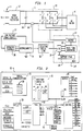
- FIG. 1 The diagram of Figure 1 shows the overall system for controlling a three phase asynchronous (induction) AC motor 10.
- a DC power source here depicted as a rectifier 12 coupled to a three phase AC line 14 provides DC voltage on positive and negative DC busses 16 and 18.
- the voltage on the busses 16 and 18 is typically several hundred volts.
- the busses are not referenced to ground and thus float with respect to ground.
- the negative bus is about 390 volts below ground.
- An inverter 20 of conventional structure comprises a plurality of transistor switches connected serially in pairs A-A′, B-B′ and C-C′ across the positive and negative busses and each switch pair junction point is connected to an input of the motor 10 to energize a phase of the motor.
- A′ means A-not and always has the opposite state of A.
- An exception is imposed by an anti-overlap function which may hold both switches open for an instant during a switching interval to insure that they are not both closed at any time.
- the trigger pulses for operating the transistor switches of inverter 20 are produced by a waveform generator 22 and coupled to the inverter 20 via an output circuit 24.
- the waveform generator 22, the output circuit 24, a serial communication (SC) circuit 26 and other support functions 28 described below are all part of a single ASIC chip 30 which is referenced to the potential of the negative bus 18.
- An isolating serial link 32 including two opto-isolators couples signals between the serial communication circuit 26 and microprocessor logic or microcontroller 34 which is referenced to ground potential and which generates signals to control the operation of the waveform generator 22.
- a conventional low voltage power supply 37 supports the microcontroller 34 and controls 36. Operator controls 36 provide inputs to the microcontroller 34.
- the grounded state of the logic allows control signals from external hardware such as switches, potentiometers, relays, programmable controllers, etc. to be directly connected to this portion of the circuitry without concern for operator or installer safety or the need for high voltage wiring.
- the microcontroller 34 and the operator controls afford an interface between the operator and the waveform generator 22 through the isolating link which protects both the operator and the microcontroller from the high voltages of the DC bus 18.
- the placement of the ASIC 30 in the high voltage side allows the three negative power switching devices A′, B′ and C′ to be directly driven (the positive switching devices being switched through simple level shifting circuitry), and allows high switching frequencies without the need for expensive opto-couplers or pulse transformers.
- Bus current can be sensed by a simple shunt resistor and voltage by resistive dividers, not shown. Positive bus voltage and each phase voltage is thus monitored. Average values of these analog signals are converted to digital form and sent through the serial port for control and readout purposes.
- the ASIC 30 generates other control signals in addition to the normal gating signals. It includes PWM signal generators to provide analog references, and also provides for an external analog to digital converter. It communicates with the microcontroller 34 through a serial port which can be optically coupled with low cost components.
- the ASIC is programmed by the microcontroller by means of several addressable eight bit registers. Status information from the ASIC may be read by the microcontroller in a similar manner.
- ASIC While several technology choices are available, it is here preferred to use CMOS gate array technology to form the ASIC.
- the ASIC is shown in Figure 2 and is divided into seven functional blocks. Each block has a set of registers associated with it by which the microcontroller establishes operating conditions or monitors the state of the ASIC or its inputs. For clarity, the signal busses interconnecting the blocks are not shown.
- the serial communications block 26 is responsible for transferring data between the ASIC 30 and the microcontroller 34. It operates in an asynchronous mode, and provides error checking. Address registers 38 in this block point to the other registers in the chip.
- the waveform generator 22 is the heart of the drive. It accepts 16 bit values in three registers 40, 42 and 44 for output frequency, carrier period, and duty cycle, respectively. It also includes a ROM 46 embodying lookup tables of reference voltage values and logic driven by the register contents for addressing the look up tables and for deriving pulse width modulated switching signals.
- the waveform generator produces three output phase signals based on a well defined algorithm which allows over-modulation, current limit, and both synchronous and asynchronous carrier types of operation. It calculates the period of the output frequency at sixty degree intervals.
- An output block 48 generates six gating signals from the three phase signals produced by the waveform generator 22. Its register 50 allows anti-overlap time to be programmed. It responds to an external current limit signal and to register bits which enable the output and allow phase interchange for reversing the motor.
- Three external fault signals and a current limit signal allow the fault block 52 to disable the drive and signal a fault to the microcontroller 34 through thw serial port.
- a maximum current limit rate may be programmed.
- the fault block also monitors the gating signals and stores the number of the most recent gating signal to become active to allow diagnostic information to be displayed by the microcontroller.
- a control block 54 provides additional external inputs and outputs. It also contains registers which allow the microcontroller to manipulate bit signals in other blocks.
- Analog input and output is provided by two independent PWM signal generators and a parallel interface to an A/D converter in an analog block 56. This allows the microcontroller to monitor average bus current and to set current limit and dynamic braking references.
- a utility block 58 provides a crystal oscillator, a watchdog timer, test circuitry, and a timing signal generator.
- signals from the microcontroller are carried by the serial link 32 through an opto-isolator to the serial communications block which transfers the data to registers elsewhere on the chip according to addresses in the incoming signal.
- the data includes waveform information which is fed into the registers 40, 42 and 44 in the waveform generator 22. These registers are updated frequently by the microcontroller to continually control the waveform produced.
- the output of the waveform generator 22 is supplied to the output 48 which directly operates the negative inverter switches and operates the positive inverter switches through a simple level shifting circuit.
- An external current sensor 60 responsive to average bus current feeds a current signal to the analog circuit 56. Whenever the current exceeds a set limit, a limit signal is sent to the fault block 52, the control block 54 and the waveform generator. If this current limit occurs too often, the fault block issues a fault signal.
- the effect of the fault signal is to shut down the output circuit 48 to terminate inverter operation, and to set a fault flag in a status register in the control block 54.
- the fault block also latches into a register a code representing the type of fault which occurred and the last switch signal issued.
- the microcontroller regularly queries the status register and if a fault is found it also queries the fault block register to determine the cause of the fault.
- a watch dog circuit in the utility block 58 is reset each time the microcontroller queries the status register. If the query fails to occur within a preset time period indicative of microcontroller or serial link failure, the watch dog circuit signals the fault block which issues a fault signal to turn off the inverter.
- the ASIC chip provides a self sufficient control circuit able to function at the voltage level of the inverter bus and requiring only control data from the microcontroller which can readily be supplied over the serial link which is serviced by a relatively inexpensive optical coupler.
Landscapes
- Engineering & Computer Science (AREA)
- Power Engineering (AREA)
- Inverter Devices (AREA)
Applications Claiming Priority (2)
| Application Number | Priority Date | Filing Date | Title |
|---|---|---|---|
| US560113 | 1990-07-31 | ||
| US07/560,113 US5045988A (en) | 1990-07-31 | 1990-07-31 | Isolated adjustable frequency AC inverter control |
Publications (2)
| Publication Number | Publication Date |
|---|---|
| EP0469872A2 true EP0469872A2 (de) | 1992-02-05 |
| EP0469872A3 EP0469872A3 (en) | 1993-11-24 |
Family
ID=24236429
Family Applications (1)
| Application Number | Title | Priority Date | Filing Date |
|---|---|---|---|
| EP19910306997 Withdrawn EP0469872A3 (en) | 1990-07-31 | 1991-07-30 | Isolated adjustable frequency ac inverter control |
Country Status (3)
| Country | Link |
|---|---|
| US (1) | US5045988A (de) |
| EP (1) | EP0469872A3 (de) |
| CA (1) | CA2047593A1 (de) |
Cited By (3)
| Publication number | Priority date | Publication date | Assignee | Title |
|---|---|---|---|---|
| WO1997044887A1 (de) * | 1996-05-21 | 1997-11-27 | Siemens Aktiengesellschaft | Umrichtersystem |
| FR2832561A1 (fr) * | 2001-11-16 | 2003-05-23 | Alstom | Systeme de commande a architecture distribuee pour convertisseurs statiques de puissance |
| EP1363389A3 (de) * | 2002-05-17 | 2006-02-22 | Vacon Oyj | Wechselrichtersteuerung |
Families Citing this family (97)
| Publication number | Priority date | Publication date | Assignee | Title |
|---|---|---|---|---|
| JPH0834709B2 (ja) * | 1990-01-31 | 1996-03-29 | 株式会社日立製作所 | 半導体集積回路及びそれを使つた電動機制御装置 |
| US5423192A (en) * | 1993-08-18 | 1995-06-13 | General Electric Company | Electronically commutated motor for driving a compressor |
| US5506487A (en) * | 1991-03-28 | 1996-04-09 | General Electric Company | Systems and methods for driving a compressor with a motor |
| US5461296A (en) * | 1993-07-20 | 1995-10-24 | Eaton Corporation | Bumpless rotating start |
| US5386186A (en) * | 1993-08-04 | 1995-01-31 | Eaton Corporation | Stator flux oriented control |
| US5537308A (en) * | 1993-10-15 | 1996-07-16 | Eaton Corporation | Digital current regulator |
| SE9400701L (sv) * | 1994-03-01 | 1995-09-02 | Electrolux Ab | Sätt och anordning för styrning av en asynkronmotor |
| US5675231A (en) * | 1996-05-15 | 1997-10-07 | General Electric Company | Systems and methods for protecting a single phase motor from circulating currents |
| US5825597A (en) * | 1996-09-25 | 1998-10-20 | General Electric Company | System and method for detection and control of circulating currents in a motor |
| DE19648696A1 (de) * | 1996-11-25 | 1998-05-28 | Asea Brown Boveri | Verfahren und Vorrichtung zur Ausregelung des DC-Offsets eines Umrichters |
| US5991505A (en) * | 1996-12-09 | 1999-11-23 | Frank; Steven R. | Switching motor control apparatus |
| EP0874446A1 (de) | 1997-04-23 | 1998-10-28 | Motorola, Inc. | Schaltnetzteil-Steuerung und dessen Verfahren |
| US5862045A (en) * | 1998-04-16 | 1999-01-19 | Motorola, Inc. | Switched mode power supply controller and method |
| US6055163A (en) * | 1998-08-26 | 2000-04-25 | Northrop Grumman Corporation | Communications processor remote host and multiple unit control devices and methods for micropower generation systems |
| US6442979B1 (en) * | 1999-05-06 | 2002-09-03 | Emerson Electric Co. | Washing machine motor control device and method |
| US6215261B1 (en) * | 1999-05-21 | 2001-04-10 | General Electric Company | Application specific integrated circuit for controlling power devices for commutating a motor based on the back emf of motor |
| WO2002037654A2 (en) | 2000-11-03 | 2002-05-10 | Smc Electrical Products, Inc. | Microdrive |
| WO2003044939A1 (en) * | 2001-11-23 | 2003-05-30 | Danfoss Drives A/S | Frequency converter for different mains voltages |
| US7193337B2 (en) * | 2003-09-09 | 2007-03-20 | Honeywell International Inc. | System and method utilizing a solid state power controller (SSPC) for controlling an electrical load of a variable frequency three-phase power source |
| FR2864373B1 (fr) * | 2003-12-18 | 2006-02-17 | Invensys Appliance Controls Sa | Controleur de moteur electrique pour appareil electromenager |
| US11881814B2 (en) | 2005-12-05 | 2024-01-23 | Solaredge Technologies Ltd. | Testing of a photovoltaic panel |
| US10693415B2 (en) * | 2007-12-05 | 2020-06-23 | Solaredge Technologies Ltd. | Testing of a photovoltaic panel |
| US11296650B2 (en) | 2006-12-06 | 2022-04-05 | Solaredge Technologies Ltd. | System and method for protection during inverter shutdown in distributed power installations |
| US8319471B2 (en) | 2006-12-06 | 2012-11-27 | Solaredge, Ltd. | Battery power delivery module |
| US9130401B2 (en) | 2006-12-06 | 2015-09-08 | Solaredge Technologies Ltd. | Distributed power harvesting systems using DC power sources |
| US8319483B2 (en) * | 2007-08-06 | 2012-11-27 | Solaredge Technologies Ltd. | Digital average input current control in power converter |
| WO2009073868A1 (en) | 2007-12-05 | 2009-06-11 | Solaredge, Ltd. | Safety mechanisms, wake up and shutdown methods in distributed power installations |
| US20080144294A1 (en) * | 2006-12-06 | 2008-06-19 | Meir Adest | Removal component cartridge for increasing reliability in power harvesting systems |
| US11569659B2 (en) | 2006-12-06 | 2023-01-31 | Solaredge Technologies Ltd. | Distributed power harvesting systems using DC power sources |
| US8963369B2 (en) | 2007-12-04 | 2015-02-24 | Solaredge Technologies Ltd. | Distributed power harvesting systems using DC power sources |
| US8947194B2 (en) | 2009-05-26 | 2015-02-03 | Solaredge Technologies Ltd. | Theft detection and prevention in a power generation system |
| US9112379B2 (en) | 2006-12-06 | 2015-08-18 | Solaredge Technologies Ltd. | Pairing of components in a direct current distributed power generation system |
| US11309832B2 (en) | 2006-12-06 | 2022-04-19 | Solaredge Technologies Ltd. | Distributed power harvesting systems using DC power sources |
| US11687112B2 (en) | 2006-12-06 | 2023-06-27 | Solaredge Technologies Ltd. | Distributed power harvesting systems using DC power sources |
| US11735910B2 (en) | 2006-12-06 | 2023-08-22 | Solaredge Technologies Ltd. | Distributed power system using direct current power sources |
| US8618692B2 (en) | 2007-12-04 | 2013-12-31 | Solaredge Technologies Ltd. | Distributed power system using direct current power sources |
| US12316274B2 (en) | 2006-12-06 | 2025-05-27 | Solaredge Technologies Ltd. | Pairing of components in a direct current distributed power generation system |
| US8473250B2 (en) | 2006-12-06 | 2013-06-25 | Solaredge, Ltd. | Monitoring of distributed power harvesting systems using DC power sources |
| US11888387B2 (en) | 2006-12-06 | 2024-01-30 | Solaredge Technologies Ltd. | Safety mechanisms, wake up and shutdown methods in distributed power installations |
| US9088178B2 (en) | 2006-12-06 | 2015-07-21 | Solaredge Technologies Ltd | Distributed power harvesting systems using DC power sources |
| US11855231B2 (en) | 2006-12-06 | 2023-12-26 | Solaredge Technologies Ltd. | Distributed power harvesting systems using DC power sources |
| US8816535B2 (en) | 2007-10-10 | 2014-08-26 | Solaredge Technologies, Ltd. | System and method for protection during inverter shutdown in distributed power installations |
| US8013472B2 (en) | 2006-12-06 | 2011-09-06 | Solaredge, Ltd. | Method for distributed power harvesting using DC power sources |
| US8384243B2 (en) | 2007-12-04 | 2013-02-26 | Solaredge Technologies Ltd. | Distributed power harvesting systems using DC power sources |
| JP2008236983A (ja) * | 2007-03-23 | 2008-10-02 | Matsushita Electric Ind Co Ltd | モータ駆動装置およびモータ駆動方法 |
| RU2360354C1 (ru) * | 2007-12-04 | 2009-06-27 | Олег Анатольевич Буглаев | Вентильный электродвигатель |
| WO2009073867A1 (en) | 2007-12-05 | 2009-06-11 | Solaredge, Ltd. | Parallel connected inverters |
| WO2009072075A2 (en) * | 2007-12-05 | 2009-06-11 | Solaredge Technologies Ltd. | Photovoltaic system power tracking method |
| US8049523B2 (en) | 2007-12-05 | 2011-11-01 | Solaredge Technologies Ltd. | Current sensing on a MOSFET |
| US11264947B2 (en) | 2007-12-05 | 2022-03-01 | Solaredge Technologies Ltd. | Testing of a photovoltaic panel |
| EP2225778B1 (de) * | 2007-12-05 | 2019-06-26 | Solaredge Technologies Ltd. | Testen von solaranlagenpanelen |
| EP2272161B1 (de) | 2008-03-24 | 2014-06-25 | Solaredge Technologies Ltd. | Schaltwandler mit einem hilfskommutierungsschaltkreis zur nullstromschaltung |
| EP3719949B1 (de) | 2008-05-05 | 2024-08-21 | Solaredge Technologies Ltd. | Gleichstromleistungskombinierer |
| US8630098B2 (en) * | 2008-06-12 | 2014-01-14 | Solaredge Technologies Ltd. | Switching circuit layout with heatsink |
| GB0908111D0 (en) * | 2009-05-12 | 2009-06-24 | Peto Raymond J | A motor controller & related method |
| US8303349B2 (en) | 2009-05-22 | 2012-11-06 | Solaredge Technologies Ltd. | Dual compressive connector |
| EP2602832B1 (de) | 2009-05-22 | 2014-07-16 | Solaredge Technologies Ltd. | Elektrisch isolierter hitzeabschwächender Verbindungskasten |
| US8690110B2 (en) | 2009-05-25 | 2014-04-08 | Solaredge Technologies Ltd. | Bracket for connection of a junction box to photovoltaic panels |
| DE102009029884A1 (de) * | 2009-06-23 | 2010-12-30 | Robert Bosch Gmbh | Notverstelleinrichtung für Blattverstellsysteme von Windenergieanlagen |
| US12418177B2 (en) | 2009-10-24 | 2025-09-16 | Solaredge Technologies Ltd. | Distributed power system using direct current power sources |
| US8710699B2 (en) * | 2009-12-01 | 2014-04-29 | Solaredge Technologies Ltd. | Dual use photovoltaic system |
| US8766696B2 (en) | 2010-01-27 | 2014-07-01 | Solaredge Technologies Ltd. | Fast voltage level shifter circuit |
| CN103025637B (zh) * | 2010-07-30 | 2015-10-21 | 奥的斯电梯公司 | 参考到dc母线的电梯再生驱动控制 |
| GB2485527B (en) | 2010-11-09 | 2012-12-19 | Solaredge Technologies Ltd | Arc detection and prevention in a power generation system |
| US10673229B2 (en) | 2010-11-09 | 2020-06-02 | Solaredge Technologies Ltd. | Arc detection and prevention in a power generation system |
| US10673222B2 (en) | 2010-11-09 | 2020-06-02 | Solaredge Technologies Ltd. | Arc detection and prevention in a power generation system |
| US10230310B2 (en) | 2016-04-05 | 2019-03-12 | Solaredge Technologies Ltd | Safety switch for photovoltaic systems |
| JP5733558B2 (ja) * | 2010-11-24 | 2015-06-10 | 日新電機株式会社 | 太陽光発電システムの出力制御方法 |
| CA2819461A1 (en) | 2010-11-30 | 2012-06-07 | Newlife Sciences Llc | Apparatus and method for treatment of pain with body impedance analyzer |
| GB2486408A (en) | 2010-12-09 | 2012-06-20 | Solaredge Technologies Ltd | Disconnection of a string carrying direct current |
| GB2483317B (en) | 2011-01-12 | 2012-08-22 | Solaredge Technologies Ltd | Serially connected inverters |
| EP2525486B1 (de) * | 2011-05-16 | 2018-10-17 | Siemens Aktiengesellschaft | Verfahren zum Betrieb einer Antriebssteuerungseinrichtung und nach dem Verfahren arbeitende Antriebssteuerungseinrichtung |
| US8570005B2 (en) | 2011-09-12 | 2013-10-29 | Solaredge Technologies Ltd. | Direct current link circuit |
| GB2498365A (en) | 2012-01-11 | 2013-07-17 | Solaredge Technologies Ltd | Photovoltaic module |
| GB2498791A (en) | 2012-01-30 | 2013-07-31 | Solaredge Technologies Ltd | Photovoltaic panel circuitry |
| US9853565B2 (en) | 2012-01-30 | 2017-12-26 | Solaredge Technologies Ltd. | Maximized power in a photovoltaic distributed power system |
| GB2498790A (en) | 2012-01-30 | 2013-07-31 | Solaredge Technologies Ltd | Maximising power in a photovoltaic distributed power system |
| GB2499991A (en) | 2012-03-05 | 2013-09-11 | Solaredge Technologies Ltd | DC link circuit for photovoltaic array |
| US9000829B2 (en) * | 2012-04-16 | 2015-04-07 | International Rectifier Corporation | System on chip for power inverter |
| EP3499695B1 (de) | 2012-05-25 | 2024-09-18 | Solaredge Technologies Ltd. | Schaltung für verbundene gleichstromquellen |
| US10115841B2 (en) | 2012-06-04 | 2018-10-30 | Solaredge Technologies Ltd. | Integrated photovoltaic panel circuitry |
| US9548619B2 (en) | 2013-03-14 | 2017-01-17 | Solaredge Technologies Ltd. | Method and apparatus for storing and depleting energy |
| US9941813B2 (en) | 2013-03-14 | 2018-04-10 | Solaredge Technologies Ltd. | High frequency multi-level inverter |
| EP4318001A3 (de) | 2013-03-15 | 2024-05-01 | Solaredge Technologies Ltd. | Umgehungsmechanismus |
| US9318974B2 (en) | 2014-03-26 | 2016-04-19 | Solaredge Technologies Ltd. | Multi-level inverter with flying capacitor topology |
| US10353345B2 (en) | 2015-02-13 | 2019-07-16 | Microdul Ag | Electronic circuit for controlling the operation of a watch |
| CN117130027A (zh) | 2016-03-03 | 2023-11-28 | 太阳能安吉科技有限公司 | 用于映射发电设施的方法 |
| US10599113B2 (en) | 2016-03-03 | 2020-03-24 | Solaredge Technologies Ltd. | Apparatus and method for determining an order of power devices in power generation systems |
| US11081608B2 (en) | 2016-03-03 | 2021-08-03 | Solaredge Technologies Ltd. | Apparatus and method for determining an order of power devices in power generation systems |
| US11018623B2 (en) | 2016-04-05 | 2021-05-25 | Solaredge Technologies Ltd. | Safety switch for photovoltaic systems |
| US11177663B2 (en) | 2016-04-05 | 2021-11-16 | Solaredge Technologies Ltd. | Chain of power devices |
| US12057807B2 (en) | 2016-04-05 | 2024-08-06 | Solaredge Technologies Ltd. | Chain of power devices |
| JP6916875B2 (ja) | 2016-10-27 | 2021-08-11 | パワー・インテグレーションズ・インコーポレーテッド | ハーフブリッジインバーターモジュールのための単線バス複数グループ異常通信 |
| DE102016222195A1 (de) | 2016-11-11 | 2018-05-17 | Ejot Gmbh & Co. Kg | Stellschraube |
| US11264918B2 (en) | 2017-12-14 | 2022-03-01 | Kohler Co. | Isolated inverters |
| WO2020252406A1 (en) | 2019-06-12 | 2020-12-17 | Truerelief, Llc | System and method for delivering pulsed electric current to living tissue |
| US11911605B2 (en) | 2021-03-05 | 2024-02-27 | Truerelief Llc | Method and apparatus for injury treatment |
Family Cites Families (7)
| Publication number | Priority date | Publication date | Assignee | Title |
|---|---|---|---|---|
| US3524986A (en) * | 1967-02-06 | 1970-08-18 | Gen Electric | Semiconductor light gating of light activated semiconductor power control circuits |
| JPS6077696A (ja) * | 1983-09-30 | 1985-05-02 | Matsushita Electric Ind Co Ltd | インバ−タ駆動制御装置 |
| US4575668A (en) * | 1984-07-09 | 1986-03-11 | Liebert Corporation | Controller for providing PWM drive to an A.C. motor |
| CA1292769C (en) * | 1986-11-12 | 1991-12-03 | Errol E. Wallingford | Three-phase pwm inverter with speed control and load compensation for aninduction motor |
| US4933825A (en) * | 1987-04-09 | 1990-06-12 | Isco, Inc. | Power supply |
| US4827196A (en) * | 1987-12-03 | 1989-05-02 | E. I. Du Pont De Nemours And Company | Motor control arrangement |
| US4871743A (en) * | 1988-01-19 | 1989-10-03 | The Trustees Of Princeton University | L-glutamic acid derivatives |
-
1990
- 1990-07-31 US US07/560,113 patent/US5045988A/en not_active Expired - Lifetime
-
1991
- 1991-07-23 CA CA 2047593 patent/CA2047593A1/en not_active Abandoned
- 1991-07-30 EP EP19910306997 patent/EP0469872A3/en not_active Withdrawn
Cited By (5)
| Publication number | Priority date | Publication date | Assignee | Title |
|---|---|---|---|---|
| WO1997044887A1 (de) * | 1996-05-21 | 1997-11-27 | Siemens Aktiengesellschaft | Umrichtersystem |
| US6021057A (en) * | 1996-05-21 | 2000-02-01 | Siemens Aktiengesellschaft | Inverter system |
| FR2832561A1 (fr) * | 2001-11-16 | 2003-05-23 | Alstom | Systeme de commande a architecture distribuee pour convertisseurs statiques de puissance |
| WO2003043168A3 (fr) * | 2001-11-16 | 2004-02-26 | Alstom | Systeme de commande a architecture distribuee pour convertisseurs statiques de puissance |
| EP1363389A3 (de) * | 2002-05-17 | 2006-02-22 | Vacon Oyj | Wechselrichtersteuerung |
Also Published As
| Publication number | Publication date |
|---|---|
| US5045988A (en) | 1991-09-03 |
| CA2047593A1 (en) | 1992-02-01 |
| EP0469872A3 (en) | 1993-11-24 |
Similar Documents
| Publication | Publication Date | Title |
|---|---|---|
| US5045988A (en) | Isolated adjustable frequency AC inverter control | |
| US4994950A (en) | Waveform generator for inverter control | |
| US4641069A (en) | Plural motor changeover control system | |
| US5270622A (en) | Brushless motor control system | |
| US6005366A (en) | Controller for power device and drive controller for motor | |
| US4620140A (en) | Control device for variable speed electric motor | |
| KR890012440A (ko) | Ac 전동기 구동 장치용 통합전류 감지 토오크 제어장치 | |
| JPS5843177A (ja) | 出力駆動段によつて制御される消費機器のための電流調節回路 | |
| CA2112238A1 (en) | Programmed pwm inverter controller | |
| CN101860290A (zh) | 多功能交流伺服驱动器 | |
| US4980838A (en) | Digital robot control having pulse width modulator operable with reduced noise | |
| EP0399236A3 (de) | Dreipunktregler mit nur einem Regel-Eingang und nur einer Stromversorgung | |
| US5177678A (en) | Inverter apparatus for preventing an overincrease of output frequency | |
| EP0078117A2 (de) | Wechselrichterschaltung | |
| CN101090246A (zh) | 三合一的交流伺服驱动器 | |
| RU2193630C1 (ru) | Устройство управления электроприводами экскаватора | |
| CA2128631A1 (en) | Integrated Interface Circuit for Driving a Subscriber Line | |
| JP2664994B2 (ja) | ブラインドの制御装置 | |
| US5919260A (en) | Electrical apparatus producing direct computer controlled variance in operation of an electrical end device | |
| JPH06165515A (ja) | インバータ | |
| KR100335798B1 (ko) | 인버터 일체형 유도전동기 | |
| JP4033273B2 (ja) | インバータの並列運転制御方法 | |
| KR0136694B1 (ko) | 교류서보모터 구동제어장치 | |
| JPH06508500A (ja) | 中間回路モニタを有する電力変換回路 | |
| RU52283U1 (ru) | Устройство для управления преобразователем частоты с многоуровневым инвертором напряжения |
Legal Events
| Date | Code | Title | Description |
|---|---|---|---|
| PUAI | Public reference made under article 153(3) epc to a published international application that has entered the european phase |
Free format text: ORIGINAL CODE: 0009012 |
|
| AK | Designated contracting states |
Kind code of ref document: A2 Designated state(s): GB IT |
|
| PUAL | Search report despatched |
Free format text: ORIGINAL CODE: 0009013 |
|
| AK | Designated contracting states |
Kind code of ref document: A3 Designated state(s): GB IT |
|
| STAA | Information on the status of an ep patent application or granted ep patent |
Free format text: STATUS: THE APPLICATION IS DEEMED TO BE WITHDRAWN |
|
| 18D | Application deemed to be withdrawn |
Effective date: 19940627 |