EP0469522B1 - Méthode et appareil pour la fabrication de fibres de carbone fines vapo-déposées - Google Patents
Méthode et appareil pour la fabrication de fibres de carbone fines vapo-déposées Download PDFInfo
- Publication number
- EP0469522B1 EP0469522B1 EP91112728A EP91112728A EP0469522B1 EP 0469522 B1 EP0469522 B1 EP 0469522B1 EP 91112728 A EP91112728 A EP 91112728A EP 91112728 A EP91112728 A EP 91112728A EP 0469522 B1 EP0469522 B1 EP 0469522B1
- Authority
- EP
- European Patent Office
- Prior art keywords
- furnace
- fine fibers
- vapor
- catalyst
- fiber
- Prior art date
- Legal status (The legal status is an assumption and is not a legal conclusion. Google has not performed a legal analysis and makes no representation as to the accuracy of the status listed.)
- Expired - Lifetime
Links
- 239000000835 fiber Substances 0.000 title claims description 151
- 238000004519 manufacturing process Methods 0.000 title claims description 26
- 239000007789 gas Substances 0.000 claims description 51
- 239000003054 catalyst Substances 0.000 claims description 44
- 239000002994 raw material Substances 0.000 claims description 25
- 230000015572 biosynthetic process Effects 0.000 claims description 24
- 239000012159 carrier gas Substances 0.000 claims description 24
- 238000010276 construction Methods 0.000 claims description 24
- 238000007599 discharging Methods 0.000 claims description 14
- 239000010419 fine particle Substances 0.000 claims description 11
- 239000000126 substance Substances 0.000 claims description 11
- 230000003405 preventing effect Effects 0.000 claims description 5
- 230000001105 regulatory effect Effects 0.000 claims description 5
- 230000009545 invasion Effects 0.000 claims description 4
- 230000033001 locomotion Effects 0.000 claims description 3
- 238000011144 upstream manufacturing Methods 0.000 claims description 3
- XEEYBQQBJWHFJM-UHFFFAOYSA-N Iron Chemical compound [Fe] XEEYBQQBJWHFJM-UHFFFAOYSA-N 0.000 description 16
- 229910052751 metal Inorganic materials 0.000 description 14
- 239000002184 metal Substances 0.000 description 14
- UFHFLCQGNIYNRP-UHFFFAOYSA-N Hydrogen Chemical compound [H][H] UFHFLCQGNIYNRP-UHFFFAOYSA-N 0.000 description 13
- 229910052739 hydrogen Inorganic materials 0.000 description 13
- 239000001257 hydrogen Substances 0.000 description 13
- 239000004215 Carbon black (E152) Substances 0.000 description 11
- 229930195733 hydrocarbon Natural products 0.000 description 11
- 150000002430 hydrocarbons Chemical class 0.000 description 11
- PXHVJJICTQNCMI-UHFFFAOYSA-N Nickel Chemical compound [Ni] PXHVJJICTQNCMI-UHFFFAOYSA-N 0.000 description 10
- 238000000034 method Methods 0.000 description 10
- UHOVQNZJYSORNB-UHFFFAOYSA-N Benzene Chemical compound C1=CC=CC=C1 UHOVQNZJYSORNB-UHFFFAOYSA-N 0.000 description 9
- 239000000758 substrate Substances 0.000 description 9
- OKTJSMMVPCPJKN-UHFFFAOYSA-N Carbon Chemical compound [C] OKTJSMMVPCPJKN-UHFFFAOYSA-N 0.000 description 8
- 229910052742 iron Inorganic materials 0.000 description 8
- 229910052799 carbon Inorganic materials 0.000 description 7
- 229920000049 Carbon (fiber) Polymers 0.000 description 5
- 238000009825 accumulation Methods 0.000 description 5
- 239000004917 carbon fiber Substances 0.000 description 5
- 239000002134 carbon nanofiber Substances 0.000 description 5
- 239000000919 ceramic Substances 0.000 description 5
- 229910017052 cobalt Inorganic materials 0.000 description 5
- 239000010941 cobalt Substances 0.000 description 5
- GUTLYIVDDKVIGB-UHFFFAOYSA-N cobalt atom Chemical compound [Co] GUTLYIVDDKVIGB-UHFFFAOYSA-N 0.000 description 5
- 238000007667 floating Methods 0.000 description 5
- VNWKTOKETHGBQD-UHFFFAOYSA-N methane Chemical compound C VNWKTOKETHGBQD-UHFFFAOYSA-N 0.000 description 5
- 229910052759 nickel Inorganic materials 0.000 description 5
- 239000007792 gaseous phase Substances 0.000 description 4
- 229910052723 transition metal Inorganic materials 0.000 description 4
- 150000003623 transition metal compounds Chemical class 0.000 description 4
- 150000003624 transition metals Chemical class 0.000 description 4
- VYPSYNLAJGMNEJ-UHFFFAOYSA-N Silicium dioxide Chemical compound O=[Si]=O VYPSYNLAJGMNEJ-UHFFFAOYSA-N 0.000 description 3
- 230000007423 decrease Effects 0.000 description 3
- 230000005484 gravity Effects 0.000 description 3
- 239000007788 liquid Substances 0.000 description 3
- 239000000047 product Substances 0.000 description 3
- IJGRMHOSHXDMSA-UHFFFAOYSA-N Atomic nitrogen Chemical compound N#N IJGRMHOSHXDMSA-UHFFFAOYSA-N 0.000 description 2
- YTPLMLYBLZKORZ-UHFFFAOYSA-N Thiophene Chemical compound C=1C=CSC=1 YTPLMLYBLZKORZ-UHFFFAOYSA-N 0.000 description 2
- 230000001174 ascending effect Effects 0.000 description 2
- 238000005255 carburizing Methods 0.000 description 2
- 238000002485 combustion reaction Methods 0.000 description 2
- 230000000694 effects Effects 0.000 description 2
- KTWOOEGAPBSYNW-UHFFFAOYSA-N ferrocene Chemical compound [Fe+2].C=1C=C[CH-]C=1.C=1C=C[CH-]C=1 KTWOOEGAPBSYNW-UHFFFAOYSA-N 0.000 description 2
- 238000005243 fluidization Methods 0.000 description 2
- 238000010438 heat treatment Methods 0.000 description 2
- 239000011261 inert gas Substances 0.000 description 2
- -1 liguid Substances 0.000 description 2
- 239000000463 material Substances 0.000 description 2
- 238000011084 recovery Methods 0.000 description 2
- 239000004071 soot Substances 0.000 description 2
- UGFAIRIUMAVXCW-UHFFFAOYSA-N Carbon monoxide Chemical compound [O+]#[C-] UGFAIRIUMAVXCW-UHFFFAOYSA-N 0.000 description 1
- RWSOTUBLDIXVET-UHFFFAOYSA-N Dihydrogen sulfide Chemical compound S RWSOTUBLDIXVET-UHFFFAOYSA-N 0.000 description 1
- PNEYBMLMFCGWSK-UHFFFAOYSA-N aluminium oxide Inorganic materials [O-2].[O-2].[O-2].[Al+3].[Al+3] PNEYBMLMFCGWSK-UHFFFAOYSA-N 0.000 description 1
- 229910002091 carbon monoxide Inorganic materials 0.000 description 1
- 238000006243 chemical reaction Methods 0.000 description 1
- 238000004140 cleaning Methods 0.000 description 1
- 238000000354 decomposition reaction Methods 0.000 description 1
- 230000008021 deposition Effects 0.000 description 1
- 230000008030 elimination Effects 0.000 description 1
- 238000003379 elimination reaction Methods 0.000 description 1
- 238000001125 extrusion Methods 0.000 description 1
- 239000012467 final product Substances 0.000 description 1
- 229910002804 graphite Inorganic materials 0.000 description 1
- 239000010439 graphite Substances 0.000 description 1
- 229910000037 hydrogen sulfide Inorganic materials 0.000 description 1
- 238000011835 investigation Methods 0.000 description 1
- 230000001788 irregular Effects 0.000 description 1
- 150000002736 metal compounds Chemical class 0.000 description 1
- 239000002923 metal particle Substances 0.000 description 1
- 150000002739 metals Chemical class 0.000 description 1
- 238000002156 mixing Methods 0.000 description 1
- 238000012986 modification Methods 0.000 description 1
- 230000004048 modification Effects 0.000 description 1
- 239000003345 natural gas Substances 0.000 description 1
- 229910052757 nitrogen Inorganic materials 0.000 description 1
- 150000002894 organic compounds Chemical class 0.000 description 1
- 150000002898 organic sulfur compounds Chemical class 0.000 description 1
- 239000002245 particle Substances 0.000 description 1
- 230000002093 peripheral effect Effects 0.000 description 1
- 229910052573 porcelain Inorganic materials 0.000 description 1
- 238000007790 scraping Methods 0.000 description 1
- 238000007789 sealing Methods 0.000 description 1
- 229910052710 silicon Inorganic materials 0.000 description 1
- 239000010703 silicon Substances 0.000 description 1
- 150000003377 silicon compounds Chemical class 0.000 description 1
- 239000007787 solid Substances 0.000 description 1
- 239000007921 spray Substances 0.000 description 1
- 150000003464 sulfur compounds Chemical class 0.000 description 1
- 239000000725 suspension Substances 0.000 description 1
- 238000005979 thermal decomposition reaction Methods 0.000 description 1
- 229930192474 thiophene Natural products 0.000 description 1
- 239000011882 ultra-fine particle Substances 0.000 description 1
Images

Classifications
-
- F—MECHANICAL ENGINEERING; LIGHTING; HEATING; WEAPONS; BLASTING
- F27—FURNACES; KILNS; OVENS; RETORTS
- F27B—FURNACES, KILNS, OVENS, OR RETORTS IN GENERAL; OPEN SINTERING OR LIKE APPARATUS
- F27B9/00—Furnaces through which the charge is moved mechanically, e.g. of tunnel type; Similar furnaces in which the charge moves by gravity
- F27B9/14—Furnaces through which the charge is moved mechanically, e.g. of tunnel type; Similar furnaces in which the charge moves by gravity characterised by the path of the charge during treatment; characterised by the means by which the charge is moved during treatment
- F27B9/20—Furnaces through which the charge is moved mechanically, e.g. of tunnel type; Similar furnaces in which the charge moves by gravity characterised by the path of the charge during treatment; characterised by the means by which the charge is moved during treatment the charge moving in a substantially straight path tunnel furnace
- F27B9/24—Furnaces through which the charge is moved mechanically, e.g. of tunnel type; Similar furnaces in which the charge moves by gravity characterised by the path of the charge during treatment; characterised by the means by which the charge is moved during treatment the charge moving in a substantially straight path tunnel furnace being carried by a conveyor
- F27B9/243—Endless-strand conveyor
-
- F—MECHANICAL ENGINEERING; LIGHTING; HEATING; WEAPONS; BLASTING
- F27—FURNACES; KILNS; OVENS; RETORTS
- F27B—FURNACES, KILNS, OVENS, OR RETORTS IN GENERAL; OPEN SINTERING OR LIKE APPARATUS
- F27B9/00—Furnaces through which the charge is moved mechanically, e.g. of tunnel type; Similar furnaces in which the charge moves by gravity
- F27B9/14—Furnaces through which the charge is moved mechanically, e.g. of tunnel type; Similar furnaces in which the charge moves by gravity characterised by the path of the charge during treatment; characterised by the means by which the charge is moved during treatment
- F27B9/20—Furnaces through which the charge is moved mechanically, e.g. of tunnel type; Similar furnaces in which the charge moves by gravity characterised by the path of the charge during treatment; characterised by the means by which the charge is moved during treatment the charge moving in a substantially straight path tunnel furnace
- F27B9/26—Furnaces through which the charge is moved mechanically, e.g. of tunnel type; Similar furnaces in which the charge moves by gravity characterised by the path of the charge during treatment; characterised by the means by which the charge is moved during treatment the charge moving in a substantially straight path tunnel furnace on or in trucks, sleds, or containers
Definitions
- This invention relates to a method and an apparatus for producing fine fibers in a floating state by heating a catalyst for generating fibers, a raw material gas for fibers, and a carrier gas.
- vapor-grown carbon fibers As fine fibers to be produced by such vapor-growing has been known, for example, vapor-grown carbon fibers.
- a substrate comprising porcelain such as alumina and the like or graphite or the like is placed in an electric furnace, with which is formed a ultra-fine particle catalyst of iron, nickel, or cobalt as a core for growth of carbon fibers, over which is introduced a mixed gas of a hydrocarbon gas such as benzene or the like and a hydrogen carrier gas so as to decompose the hydrocarbon at a temperature of 800 to 1300 °C, thereby carbon fibers can be grown on the substrate.
- a hydrocarbon gas such as benzene or the like
- a hydrogen carrier gas so as to decompose the hydrocarbon at a temperature of 800 to 1300 °C
- the present applicant has already used an organic metal compound which is evaporated to make a matal catalyst in a gaseous phase to give a novel procedure, thereby it has been made possible to omit three operations of dispersing a conventional catalyst on a substrate, reducing in a furnace, and withdrawing formed fibers toward the outside of the furnace, and a gas of an organic compound as a carbon source in the gaseous phase and a gas of an organic transition metal compound as a catalyst source are subjected to thermal decomposition in an electric furnace heated to a required temperature, thereby the catalyst and the carbon fiber are continuously produced in a floating state to develop a means which has been filed as a patent application, resulting in allowance of a patent (Japanese Patent Publication No. 62-49363).
- catalyst particles generated in the electric furnace for example, iron fine particles generated by decomposition of a gas of ferrocene (a state of which is not clear as pure iron, carbite of iron, or any one of solid, liguid, or gas) adhere to a wall of the furnace, which form fibers in a manner of the substrate method, and the fibers trap floating fibers to increase the accumulation.
- the floating fibers adhere to the wall of the furnace for some reason, and the floating fibers deposit due to the gravity especially in the case of a furnace of the horizontal type.
- a gas containing hydrogen is generally used as the carrier gas, so that the fibers must be scraped after replacing the inside of the furnace with a noncombustible gas such as nitrogen or the like, and hence no satisfactory operation performance is obtained.
- a method has also been proposed in which a scraping unit of the screw type is provided at the inside of the furnace, and the accumulated fibers are continuously scraped during operation, however, there is a problem that the catalyst fine particles adhere to the screw to allow fibers to grow, and the operation performance inversely decreases due to elimination thereof.
- the present invention is directed to a problem of clogging due to fibers in a furnace in the fluidization gaseous phase method which basically has a high productivity, wherein no way of solution is given even on the analogy of the method of the above mentioned U.S. Patent.
- the present inventors have done various investigations on the improvement of the operation performance and the improvement of the degree of freedom of decision on fiber diameter in the production of fine fibers by the vapor-growing method, and found that although the formation of fibers and the thickness growth thereof were conventionally performed at the same time in one furnace, the problems can be solved by separating the both steps, resulting in accomplishment of the present invention.
- a first apparatus for production of vapor-grown fine fibers has the construction of a furnace provided with a furnace of the vertical type and a furnace of the horizontal type connected so as to intersect in an L-shaped configuration, wherein at an upper part of said furnace of the vertical type there is provided a first injecting means for supplying the necessary components for fiber formation such as the raw material, the catalyst or a catalyst forming substance, the carrier gas and the like, at the inside of said furnace of the horizontal type there is provided a conveying means for transporting formed fine fibers from a linking proximal portion of said furnace of the vertical type to its other end portion, and at the side of said other end portion with respect to said furnace of the vertical type there are provided a fiber withdrawing means and a gas discharging means.
- Fig. 1 is an illustrative cross-sectional view showing an example of the apparatus for producing vapor-grown fine fibers according to the present invention.
- Fig. 2 is an illustrative cross-sectional view showing another example of the apparatus for producing vapor-grown fine fibers according to the present invention.
- Fig. 3 is an illustrative cross-sectional view showing still another example of the apparatus for producing vapor-grown fine fibers according to the present invention.
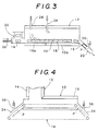
- Fig. 4 is an illustrative cross-sectional view of an important part showing a modified example of the apparatus for producing vapor-grown fine fibers according to the present invention.
- the furnace of the vertical type and the furnace of the horizontal type may be constructed such that each furnace temperature can be independently regulated.
- the furnace of the horizontal type may be provided with a second injecting means for supplying necessary components for fiber growth except for the catalyst.
- the conveying means may be constructed such that a conveying speed can be established in a variable manner.
- a cross section of the furnace is made rectangular, and a plurality of the first injecting means are provided at the upper part of the furnace of the vertical type.
- a second apparatus for production of vapor-grown fine fibers in accordance with the invention has the construction of a furnace of the horizontal type wherein at one end portion thereof there is provided a first injecting means for supplying the necessary components for fiber formation such as the raw material, the catalyst or a catalyst forming substance, the carrier gas and the like, at the side of the other end portion there are provided a fiber withdrawing means and a gas discharging means, there is further provided a conveying means for transporting formed fine fibers from a downward position below said first injecting means to the fiber withdrawing means, and there is provided a means for preventing invasion of atmosphere gas into the inside of said furnace, wherein downstream of the first injecting means there is provided at least one second injecting means for supplying the necessary components for fiber growth including neither the catalyst nor the catalyst forming substance.
- the furnace of the horizontal type is divided into two ones locating at an upstream side and a downstream side with respect to the second injecting means, and a furnace temperature of each of the divided furnaces can be independently regulated.
- a method for production of vapor-grown fine fibers wherein the necessary components for fiber formation, i.e. the raw material, the catalyst or a catalyst forming substance, the carrier gas and the like are injected from an upward position of a furnace into the inside of the furnace, thereby fine fibers are formed from falling catalyst fine particles, the fibers are accumulated on a conveying means to achieve fiber thickness growth with movement in the horizontal direction thereof, and the fine fibers thus grown are continuously withdrawn from the furnace.
- the necessary components for fiber formation i.e. the raw material, the catalyst or a catalyst forming substance, the carrier gas and the like are injected from an upward position of a furnace into the inside of the furnace, thereby fine fibers are formed from falling catalyst fine particles, the fibers are accumulated on a conveying means to achieve fiber thickness growth with movement in the horizontal direction thereof, and the fine fibers thus grown are continuously withdrawn from the furnace.
- the catalyst herein may be an organic transition metal compound such as iron, nickel, cobalt or the like which decomposes to form metal fine particles which serve as cores for formation of fibers, or may be the above mentioned metal fine particles themselves.
- the metal fine particles may be carried on the carrier gas as such to spray in the furnace, or they may be injected into the furnace in a state of suspension in liquid hydrocarbon which serves as a raw material for fibers.
- an organic transition metal which may be dissolved in hydrocarbon may be preferably used rather than the case in which the metal particles are used.
- the diameter of the fine fiber can be freely established by selecting a conveying speed of the plates conveyed in the furnace of the horizontal type, and a concentration and a temperature of the raw material gas in the furnace of the horizontal type. Therefore, in order to restrict fiber adhesion to the inner wall of the furnace of the vertical type, even when the gas staying period in the furnace of the vertical type is made short by making the length of the furnace of the vertical type short, or by making the injecting amount of the first injecting means large to make a linear speed of the gas large, even if the diameter of the fine fiber falling onto the plates becomes thin on account of the above, there is given no limitation to a diameter of the final product.
- the metal fine particles formed in the furnace of the vertical type form the fine fibers with falling.
- the fine fibers are accumulated on the plates, which are subjected to thickness growth with being conveyed in the furnace of the horizontal type and they are withdrwan from the furnace together with the plates.
- the production of the fine fibers is continuously carried out without changing a furnace temperature and each injecting amount, and new plates are supplied continuously or intermittently, and plates on which grown fine fibers are accumulated are withdrawn continuously or intermittently.
- the first injecting means for supplying necessary components for fiber formation such as a raw material, a catalyst or a catalyst forming substance, a carrier gas and the like, and the other constructions are the same as described above, thereby vapor-grown fine fibers can be produced in the same manner as described above.
- the injecting direction may be any one of a vertical direction or a horizontal direction.
- Fig. 1 is an illustrative construction figure showing an example of an apparatus for producing vapor-grown fine fibers according to the present invention.
- a reference numeral 10 indicates a furnace of the vertical type and 12 a furnace of the horizontal type respectively, and the furnace of the vertical type 10 is connected with the furnace of the horizontal type 12 at one end portion with intersecting in an L-shaped configuration.
- a construction is given such that at outer peripheral portions of the above mentioned furnace of the vertical type 10 and the furnace of the horizontal type 12 are arranged independent heaters 14 and 16 respectively, and temperature conditions and the like can be independently adjusted with respect to each of the furnaces.
- the structure of the furnace is generally a cylindrical configuration having a circular cross-section, and for the inner wall of the furnace is used quartz glass, ceramics, metal or the like which resists to a furnace temperature (800 to 1300 °C) and does not contain iron, nickel, cobalt, or other transition metals which serves as a catalyst for fiber formation.
- quartz glass, ceramics, metal or the like which resists to a furnace temperature (800 to 1300 °C) and does not contain iron, nickel, cobalt, or other transition metals which serves as a catalyst for fiber formation.
- these materials must be those which do not react with hydrogen which is mainly used as a carrier gas and with carbon to be formed.
- the cross section of the furnace may be a rectangular parallelopiped type in relation to the conveying means.
- a length of the furnace differs depending on production conditions, for which it is preferable that usually a length of the furnace of the vertical type 10 may be established to be a length such that non-decomposed organic transition metal compounds decrease to be not more than 20% at an outlet (inlet of the furnace of the horizontal type).
- a conveying means 18 such as an endless conveyer or the like which extends from the linking portion with the furnace of the vertical type 10 to the other end portion.
- the conveyer as the conveying means 18 may be used quartz glass, ceramics, or metal which resists to a furnace temperature ( 800 to 1300 °C) and does not contain iron, nickel, cobalt, or other tansition metals which serves as a catalyst for fiber formation in the same manner as the above mentioned inner wall of the furnace.
- it may be constructed as a belt conveyer in which ceramic plates are connected by a ceramic chain to be rotated at the inside of the furnace as shown in the figure, or it may be constructed to go to the outside of the furnace at the other end portion so as to return at the outside of the furnace (see Fig. 4).
- material qualities of rollers, bearings and the like which are installed in the furnace it is necessary for material qualities of rollers, bearings and the like which are installed in the furnace to contain no metal component which serves as a catalyst and to be excellent in heat resistance.
- this gas discharging means 24 is not necessarily provided together with the fiber withdrawing means 22, which can be provided at the vicinity of the opening port 20 of the conveying means 18 at which the fiber withdrawing means 22 is provided.
- an outlet portion of the conveyer constructs the fiber withdrawing means and the gas discharging means.
- a first injecting means 26 for supplying necessary components for fiber formation.
- this injecting means 26 for example, a construction is given such that a catalyst forming substance is dissolved in hydrocarbon, which is sent as a liquid to a preheater by means of a quantitative pump to be completely vaporized by the preheater after mixing with a carrier gas, and an obtained mixed gas is sent to the furnace of the vertical type 10.
- a larger cross section of the furnace of the vertical type 10 is preferable becuase of a little ahdesion of fibers.
- the cross section of the furnace is made large and the number of the injecting means 26 is made many rather than many furnaces are provided together.
- the heaters 14,16 are actuated beforehand to adjust the furnace of the vertical type 10 and the furnace of the horizontal type 12 to be in required temperature conditions respectively, and then necessary components for fiber formation such as a raw material, a catalyst, a carrier gas and the like are supplied to the inside of the furnace from the first injecting means 26 provided at the upper part of the furnace of the vertical type 10. As a result, certain fibers are formed by vapor-growth at the inside of the furnace of the vertical type 10.
- such a construction may be available that at one end portion of the furnace of the horizontal type 12 for linking with the furnace of the vertical type 10 is provided a second injecting means 28, from an injecting port of which are optionally injected necessary components for fiber formation such as a raw material, a carrier gas and the like except for a catalyst.
- a raw material consumed in the furnace of the vertical type 10 may be replenished to establish the inside of the furnace of the horizontal type 12 to have a higher concentration than that of the inside of the furnace of the vertical type 10.
- a plurality of the injecting means 28 are provided in the length direction of the furnace of the horizontal type 12, and the raw material gas is compensated for a degree of consumption so as to maintain a raw material gas concentration to be constant.
- a plurality of the injecting means 28 may be provided in the width direction.
- the raw material and the carrier gas may be supplied from separate injecting ports, however, it is preferable to use the same injecting port from a viewpoint of preventing generation of soot. Further, it is effective to preheat the injecting gas beforehand within a range not to exceed a decomposing temperature of the raw material because the temperature irregularity is not made large.
- Fig. 2 is an illustrative construction figure showing another example of the production apparatus for vapor-grown fine fibers according to the present invention.
- the same construction parts as those of the apparatus shown in Fig. 1 are designated by the same reference numerals, detailed explanation of which will be omitted.
- the apparatus shown in Fig. 2 represents another example of the conveying means 18 provided at the inside of the furnace of the horizontal type 12, which is constructed such that when the chain which contains no catalyst metal component as in the example shown in Fig.
- independent plates 19 comprising ceramics or the like [that is quartz glass, metal or the like which resists to a furnace temperature ( 800 to 1300 °C) and does not contain iron, nickel, cobalt or other transition metals which serves as a catalyst for fiber formation] are arranged, the plates 19 are sequentially supplied from a supplying means 30 provided at the side of one end portion of the furnace of the horizontal type 12, they are extruded one by one toward the side of the other end portion of the furnace of the horizontal type 12 by means of an extruding means 32 such as a pusher or the like to transport, and the plates 19 extruded at the side of the other end portion of the furnace of the horizontal type 12 are sequentially transported to the fiber withdrawing means 22 so as to perform recovery of fibers there, thereby recovery of fibers can be smoothly achieved.
- the plates 19 are introduced into the chamber, the inside of this chamber is firstly replaced by an inert gas, and then replacement is completely performed by a carrier gas, after which extrusion is carried out by the extruding means 32 so as to move the plates 19 in the inside of the furnace 12 by a degree of one individual at the same time.
- the above mentioned chamber is sufficiently intersepted from the furnace 12 and the outside air by means of an opening and closing shutter. If this interseption is insufficient, when one shutter is opened, the gas in the chamber forms an ascending stream to escape to the outside air, and air invades from the fiber withdrawing means 22 into the inside of the furnace to give a dangerous state.
- a lid is provided at a plate outlet of the fiber withdrawing means 22, which opens or closes depending on falling momentum of the plates 19 or automatically after detecting falling of the plates 19.
- the plates 19 are supplied to the chamber from a downward portion so as to make a height of a plate supplying port of the chamber even to the outlet of the fiber withdrawing means 22, thereby generation of the ascending gas stream can be prevented.
- the second injecting means 28 is effective provided that it is at the vicinity of the linking portion between the furnace of the horizontal type 12 and the furnace of the vertical type 10, which may be provided at a position, for example, shown in Fig. 2.
- an inner pressure in order to prevent invasion of air into the furnace, it is preferable to establish an inner pressure to be slightly higher than the atmospheric pressure.
- a combustible gas such as hydrogen or the like
- a construction may be given such that a gas discharging port 36 is provided at a part of a passage which forms the fiber withdrawing means 22, and exhaust gas is subjected to combustion at this gas discharging port 36, thereby a boundary surface P is formed owing to difference in specific gravities of air and hydrogen at the vicinity of the gas discharging port 36 of the above mentioned passage, and air is not allowed to enter into the inside of the furnace.
- Fig. 3 is an illustrative construction figure showing still another example of the production apparatus for vapor-grown fine fibers according to the present invention.
- the same construction parts as those of the apparatuses shown in Fig. 1 through Fig. 2 are designated by the same reference numerals, detailed explanation of which will be omitted.
- the apparatus shown in Fig. 3 there is provided such a construction that when the height of the furnace of the horizontal type 12 is made large, the height of the furnace of the vertical type is made substantially zero, and it comprises the furnace of the horizontal type 12 only. Therefore, in the present example, at an upper part at the side of one end portion of the above mentioned furnace of the horizontal type 12 is provided the first injecting means 26 for supplying components necessary for fiber formation.
- the conveyor as the conveying means 18 is made porous, and at the downward side from the lower conveyer of the furnace of the vertical type 10 is provided a gas suction hole, thereby a gas injected from the first injecting means 26 and passed through the furnace of the vertical type 10 is completely exhaused, and a concentration of the organic transition metal compound which is a catalyst for fiber formation is made substantially zero in the furnace of the horizontal type 12, thereby generation of fibers on the conveyer can be prevented.
- a concentration of the organic transition metal compound which is a catalyst for fiber formation is made substantially zero in the furnace of the horizontal type 12, thereby generation of fibers on the conveyer can be prevented.
- a metal wire brush or the like is used at the inlet or the outlet of this conveying means 18 so as to perform peeling and cleaning of the surface, thereby it can be prevented that fibers partly adhered to the conveying means 18 repeatedly pass through the inside of the furnace of the horizontal type 12 to grow into fibers having large diameters.
- the furnace of the vertical type 10 in relation to the first injecting means 26, for example, when the number of the injecting ports is many, if a cross section thereof is made rectangular, then the preventing effect of fiber adhesion can be realized by means of a more compact furnace construction.
- a carrier gas and a hydrocarbon gas are injected from the second injecting means 28, thereby it can be adjusted that fibers are made thick with moving in the furnace of the horizontal type 12.
- hydrocarbon used in the first injecting means 26 may be different from that used in the second injecting means 28.
- the first injecting means 26 in order to adjust a ratio of hydrocarbon to the organic transition metal, it is preferable that one which is a liquid at an ordinary temperature (for example, a solution in which ferrocene is dissolved in benzene at a certain ratio) is vaporized by a preheater in the presence of hydrogen to use as hydrocarbon, and in the second injecting means 28, hydrocarbon which is a gas at an ordinary temperature (for example, methane gas, or natural gas) may be mixed with hydrogen to use.
- a liquid at an ordinary temperature for example, a solution in which ferrocene is dissolved in benzene at a certain ratio
- hydrocarbon which is a gas at an ordinary temperature for example, methane gas, or natural gas
- an internal pressure is established to be slightly higher than the atmospheric pressure.
- a combustible gas such as hydrogen or the like is used as a carrier gas, in the case of a construction of the conveying means 18 as shown, for example, in Fig.
- the conveying means 18 is not necessarily a plate configuration, and when it is made as one having a box configuration, then fewer fibers formed in the furnace drop during transport.
- vapor-grown carbon fibers generally growth in the fiber length direction mainly occurs under a condition having a low carburizing tendency, while deposition of carbon at the fiber surface is vigorous under an atmosphere condition having a high carburizing tendency to accelerate the thickness growth, and metal fine particles which serve as growth ends of length are also covered with carbon to stop the growth in the length direction.
- the furnace of the vertical type is at a relatively low temperature wherein a raw material concentration in a gaseous phase is made relatively low and a hydrogen concentration is established to be relatively high so as to extend the life of the metal fine particles to be a long period to increase the efficiency of the lenght growth, while in the furnace of the horizontal type, a temperature is inversely made relatively high wherein a raw material concentraion is also made relatively high and a hydrogen concentration is established to be relatively low (provided that any one of them is in a range without generating soot) so as to increase the efficiency of the thickness growth, thereby an overall productivity is increased and nonuniformity of products can be restricted.
- the formation and growth of fibers are based on the fluidization method, wherein accumulation takes place on the conveying means 18 only, and there is no formation from a substrate. Therefore, the fibers can be recovered from the conveying means 18 with ease.
- the forming step of fibers can separated from the growing step so as to independently change conditions respectively, so that a temperature, a concentration, a staying period and the like can be freely selected depending on a catalyst, a raw material, and a carrier gas respectively used, and a diameter of the fiber can be freely established.
- a temperature, a concentration, a staying period and the like can be freely selected depending on a catalyst, a raw material, and a carrier gas respectively used, and a diameter of the fiber can be freely established.
- a little accumulation of fibers is given, and continuous operation can be performed for a long period, and as a result thereof, a high productivity can be obtained.
- little adhesion of fibers to the internal wall takes place.
Landscapes
- Engineering & Computer Science (AREA)
- Mechanical Engineering (AREA)
- General Engineering & Computer Science (AREA)
- Inorganic Fibers (AREA)
Claims (9)
- Appareil pour la fabrication de fibres de carbone fines vapo-déposées, composé d'un four équipé d'un four de type vertical (10) et d'un four de type horizontal (12) reliés de façon à présenter une intersection dans une configuration en forme de L, dans lequel sur une partie supérieure dudit four de type vertical (10), un premier moyen d'injection (26) est prévu pour fournir les éléments nécessaires à la fabrication des fibres, comme la matière brute, le catalyseur ou une substance formant le catalyseur, le gaz porteur et autres, à l'intérieur dudit four de type horizontal (12), se trouve un moyen de transport (18) pour transporter les fibres de carbone fines fabriquées depuis la partie de liaison proximale dudit four de type vertical vers son autre partie d'extrémité, et du côté de ladite autre partie d'extrémité par rapport audit four de type vertical, se trouve un moyen de défournage des fibres (22) et un moyen de décharge du gaz (24).
- Appareil pour la fabrication de fibres de carbone fines vapo-déposées selon la revendication 1, dans lequel le four de type vertical (10) et le four de type horizontal (12) sont construits de façon à ce que la température de chaque four puisse être réglée indépendamment.
- Appareil pour la fabrication de fibres de carbone fines vapo-déposées selon la revendication 1, dans lequel le four de type horizontal (12) est équipé d'au moins un deuxième moyen d'injection (28) pour fournir les éléments nécessaires à la fabrication des fibres ne comprenant ni le catalyseur, ni la substance formant le catalyseur.
- Appareil pour la fabrication de fibres de carbone fines vapo-déposées selon la revendication 3, dans lequel il est prévu un moyen pour éliminer le gaz qui est passé par le four de type vertical (10) vers l'extérieur du four sans qu'il ne passe par le four de type horizontal (12).
- Appareil pour la fabrication de fibres de carbone fines vapo-déposées selon la revendication 1, dans lequel le moyen de transport (18) est construit de façon à ce que la vitesse de transport puisse être réglée de manière variable.
- Appareil pour la fabrication de fibres de carbone fines vapo-déposées selon la revendication 1, dans lequel la section transversale du four est rectangulaire et une pluralité de premiers moyens d'injection (26) est prévue sur la partie supérieure du four de type vertical (10).
- Appareil pour la fabrication de fibres de carbone fines vapo-déposées qui a la construction d'un four de type horizontal (12), dans lequel, à une de ses parties d'extrémité, est prévu un premier moyen d'injection (26) pour fournir les éléments nécessaires à la fabrication des fibres, comme la matière brute, le catalyseur ou une substance formant le catalyseur, le gaz porteur et autres, du côté de l'autre partie d'extrémité sont prévus un moyen de défournage des fibres (22) et un moyen de décharge du gaz (36), est prévu en outre un moyen de transport (18) pour transporter les fibres de carbone fines fabriquées depuis une position inférieure, au-dessous dudit premier moyen d'injection (26), jusqu'au moyen de défournage des fibres (22) et est prévu un moyen pour empêcher la pénétration du gaz atmosphérique à l'intérieur dudit four, dans lequel en aval du premier moyen d'injection (36), il est prévu au moins un deuxième moyen d'injection (28) pour fournir les éléments nécessaires à la fabrication des fibres ne comprenant ni le catalyseur, ni la substance formant le catalyseur.
- Appareil pour la fabrication de fibres de carbone fines vapo-déposées selon la revendication 7, dans lequel le four de type horizontal (12) est divisé en deux parties, situées sur un côté en amont et un côté en aval du deuxième moyen d'injection (28), et la température de chacun des fours divisés peut être réglée indépendamment.
- Appareil pour la fabrication de fibres de carbone fines vapo-déposées, dans lequel les éléments nécessaires à la fabrication des fibres, comme la matière brute, le catalyseur ou une substance formant le catalyseur, le gaz porteur et autres sont injectés à partir d'une position supérieure d'un four à l'intérieur du four, les fibres de carbone fines sont ainsi fabriquées à partir de fines particules du catalyseur, les fibres sont rassemblées sur un moyen de transport pour achever la fabrication des fibres avec un déplacement dans la direction horizontale, et les fibres de carbone fines ainsi fabriquées sont continuellement défournées.
Applications Claiming Priority (2)
| Application Number | Priority Date | Filing Date | Title |
|---|---|---|---|
| JP199129/90 | 1990-07-30 | ||
| JP19912990 | 1990-07-30 |
Publications (2)
| Publication Number | Publication Date |
|---|---|
| EP0469522A1 EP0469522A1 (fr) | 1992-02-05 |
| EP0469522B1 true EP0469522B1 (fr) | 1996-05-29 |
Family
ID=16402625
Family Applications (1)
| Application Number | Title | Priority Date | Filing Date |
|---|---|---|---|
| EP91112728A Expired - Lifetime EP0469522B1 (fr) | 1990-07-30 | 1991-07-29 | Méthode et appareil pour la fabrication de fibres de carbone fines vapo-déposées |
Country Status (3)
| Country | Link |
|---|---|
| US (1) | US5227142A (fr) |
| EP (1) | EP0469522B1 (fr) |
| DE (1) | DE69119838T2 (fr) |
Families Citing this family (12)
| Publication number | Priority date | Publication date | Assignee | Title |
|---|---|---|---|---|
| ES2041215B1 (es) * | 1992-02-24 | 1994-05-16 | Consejo Superior Investigacion | Reactor para la mejora del rendimiento e incremento de la longitud de las fibras cortas ceramicas, especialmente de carbono, producidas a partir de gases. |
| US5837081A (en) * | 1993-04-07 | 1998-11-17 | Applied Sciences, Inc. | Method for making a carbon-carbon composite |
| US6700550B2 (en) * | 1997-01-16 | 2004-03-02 | Ambit Corporation | Optical antenna array for harmonic generation, mixing and signal amplification |
| US7160531B1 (en) * | 2001-05-08 | 2007-01-09 | University Of Kentucky Research Foundation | Process for the continuous production of aligned carbon nanotubes |
| US6787229B1 (en) | 2002-01-08 | 2004-09-07 | University Of Central Florida | Three-dimensional carbon fibers and method and apparatus for their production |
| US20040122515A1 (en) * | 2002-11-21 | 2004-06-24 | Xi Chu | Prosthetic valves and methods of manufacturing |
| JP4953606B2 (ja) * | 2004-09-15 | 2012-06-13 | 昭和電工株式会社 | 気相法炭素繊維およびその製造方法 |
| KR100664545B1 (ko) * | 2005-03-08 | 2007-01-03 | (주)씨엔티 | 탄소나노튜브 대량합성장치 및 대량합성방법 |
| CA2500766A1 (fr) * | 2005-03-14 | 2006-09-14 | National Research Council Of Canada | Methode et appareil de production et de fonctionnalisation en continu de nanotubes de carbone a simple paroi au moyen d'une torche a plasma inductif haute frequence |
| KR20090031210A (ko) * | 2007-09-21 | 2009-03-25 | 주식회사 나노베이스 | 탄소 나노튜브 코팅 장치 및 그 방법 |
| DE102015100062A1 (de) | 2015-01-06 | 2016-07-07 | Universität Paderborn | Vorrichtung und Verfahren zum Herstellen von Siliziumcarbid |
| DE102018100679A1 (de) | 2018-01-12 | 2019-07-18 | Universität Paderborn | Vorrichtung und Verfahren zum Herstellen von Siliziumcarbid |
Family Cites Families (16)
| Publication number | Priority date | Publication date | Assignee | Title |
|---|---|---|---|---|
| US2441500A (en) * | 1944-03-30 | 1948-05-11 | Miess Fred | Electrically heating continuously traveling metal strip |
| US2750272A (en) * | 1950-06-05 | 1956-06-12 | Allis Chalmers Mfg Co | Process for production of hard burned agglomerates of fine magnetite ore |
| US2668701A (en) * | 1951-02-03 | 1954-02-09 | Selas Corp Of America | Heating control system |
| FR72440E (fr) * | 1957-11-05 | 1960-04-13 | Commissariat Energie Atomique | Perfectionnements apportés aux procédés et appareils du genre de ceux pour l'obtention du fluorure d'uranium |
| US3827854A (en) * | 1973-10-26 | 1974-08-06 | W Gildersleeve | Automatic metal protecting apparatus and method |
| DE2801161B2 (de) * | 1978-01-12 | 1981-06-25 | Babcock Krauss-Maffei Industrieanlagen GmbH, 8000 München | Verfahren und Brennen von Sintergut aus karbonatischen Rohstoffen wie z.B. Zementklinker |
| US4256451A (en) * | 1979-10-26 | 1981-03-17 | Johnson Jr Allen S | Upright kiln and attendant method for heating an aggregate material |
| US4753777A (en) * | 1983-04-18 | 1988-06-28 | Toho Beslon Co., Ltd. | Apparatus for continuous production of carbon fibers |
| US4572813A (en) * | 1983-09-06 | 1986-02-25 | Nikkiso Co., Ltd. | Process for preparing fine carbon fibers in a gaseous phase reaction |
| US4475986A (en) * | 1983-09-07 | 1984-10-09 | Peabody Development Company | Stable activated carbon process using a moving grate stoker furnace |
| US4816289A (en) * | 1984-04-25 | 1989-03-28 | Asahi Kasei Kogyo Kabushiki Kaisha | Process for production of a carbon filament |
| FR2564110B1 (fr) * | 1984-05-10 | 1986-09-05 | Lorraine Carbone | Procede de production de fibres de carbone vapo-deposees a partir de methane |
| IT1178520B (it) * | 1984-09-28 | 1987-09-09 | Alusuisse Italia Spa | Procedimento e forno a tunnel per la calcinazione di corpi carboniosi, in particolare di elettrodi |
| JPS61145606A (ja) * | 1984-12-19 | 1986-07-03 | Ohkura Electric Co Ltd | 干渉対応形パタ−ン切換式温度制御装置 |
| JP2662413B2 (ja) * | 1988-04-12 | 1997-10-15 | 昭和電工株式会社 | 気相成長炭素繊維の製造方法 |
| FR2647885B1 (fr) * | 1989-05-31 | 1991-12-20 | Mustad Fils Sa O | Four-tunnel de forge a convoyeur a chaine de charges unitaires |
-
1991
- 1991-07-29 DE DE69119838T patent/DE69119838T2/de not_active Expired - Fee Related
- 1991-07-29 US US07/737,811 patent/US5227142A/en not_active Expired - Lifetime
- 1991-07-29 EP EP91112728A patent/EP0469522B1/fr not_active Expired - Lifetime
Also Published As
| Publication number | Publication date |
|---|---|
| EP0469522A1 (fr) | 1992-02-05 |
| DE69119838T2 (de) | 1996-10-02 |
| US5227142A (en) | 1993-07-13 |
| DE69119838D1 (de) | 1996-07-04 |
Similar Documents
| Publication | Publication Date | Title |
|---|---|---|
| EP0469522B1 (fr) | Méthode et appareil pour la fabrication de fibres de carbone fines vapo-déposées | |
| CN102671584B (zh) | 制备颗粒材料的反应器和方法 | |
| US6068827A (en) | Decomposition of hydrocarbon to carbon black | |
| EP1060285B1 (fr) | Appareil et procede pour le depot d'une matiere semi-conductrice | |
| US20040089237A1 (en) | Continuous chemical vapor deposition process and process furnace | |
| CN1081785C (zh) | 金属碎料运输机 | |
| NL2002590C2 (en) | Apparatus and process for atomic or molecular layer deposition onto particles during pneumatic transport. | |
| JP2002004054A (ja) | 基板上に薄膜を成長させる方法 | |
| JPH0424320B2 (fr) | ||
| WO1990008732A1 (fr) | Procede et appareil de production en continu des trichites monocristaux | |
| HU210280B (en) | Method and apparatus for coating hot glass surface | |
| CN1032534A (zh) | 玻璃的涂覆 | |
| US4637924A (en) | Continuous silicon carbide whisker production | |
| JP2971189B2 (ja) | 気相成長微細繊維の製造方法および装置 | |
| US4936250A (en) | System for coating particles employing a pneumatic transport reactor | |
| JP2919647B2 (ja) | 微細炭素繊維製造装置 | |
| JP3585248B2 (ja) | 流動気相成長微細繊維の太さ成長装置 | |
| JP3278883B2 (ja) | 流動気相成長微細繊維の製造装置 | |
| JP2004149961A (ja) | 気相成長炭素繊維取出方法及び気相成長炭素繊維取出装置 | |
| JP2501041B2 (ja) | 気相成長炭素繊維の連続製造装置 | |
| JPH04245922A (ja) | 気相成長炭素繊維の製造装置 | |
| JPH04272229A (ja) | 気相成長炭素繊維の製造装置 | |
| JPS6253418A (ja) | 炭素質繊維の連続製造方法 | |
| JPS60252721A (ja) | 炭素繊維の製造方法 | |
| JPH06316816A (ja) | 炭素繊維 |
Legal Events
| Date | Code | Title | Description |
|---|---|---|---|
| PUAI | Public reference made under article 153(3) epc to a published international application that has entered the european phase |
Free format text: ORIGINAL CODE: 0009012 |
|
| 17P | Request for examination filed |
Effective date: 19911122 |
|
| AK | Designated contracting states |
Kind code of ref document: A1 Designated state(s): DE FR GB IT |
|
| 17Q | First examination report despatched |
Effective date: 19941004 |
|
| GRAH | Despatch of communication of intention to grant a patent |
Free format text: ORIGINAL CODE: EPIDOS IGRA |
|
| GRAA | (expected) grant |
Free format text: ORIGINAL CODE: 0009210 |
|
| AK | Designated contracting states |
Kind code of ref document: B1 Designated state(s): DE FR GB IT |
|
| REF | Corresponds to: |
Ref document number: 69119838 Country of ref document: DE Date of ref document: 19960704 |
|
| ET | Fr: translation filed | ||
| ITF | It: translation for a ep patent filed | ||
| PLBE | No opposition filed within time limit |
Free format text: ORIGINAL CODE: 0009261 |
|
| STAA | Information on the status of an ep patent application or granted ep patent |
Free format text: STATUS: NO OPPOSITION FILED WITHIN TIME LIMIT |
|
| 26N | No opposition filed | ||
| REG | Reference to a national code |
Ref country code: GB Ref legal event code: IF02 |
|
| PGFP | Annual fee paid to national office [announced via postgrant information from national office to epo] |
Ref country code: FR Payment date: 20060719 Year of fee payment: 16 |
|
| PGFP | Annual fee paid to national office [announced via postgrant information from national office to epo] |
Ref country code: GB Payment date: 20060721 Year of fee payment: 16 |
|
| PGFP | Annual fee paid to national office [announced via postgrant information from national office to epo] |
Ref country code: IT Payment date: 20060731 Year of fee payment: 16 |
|
| PGFP | Annual fee paid to national office [announced via postgrant information from national office to epo] |
Ref country code: DE Payment date: 20060922 Year of fee payment: 16 |
|
| GBPC | Gb: european patent ceased through non-payment of renewal fee |
Effective date: 20070729 |
|
| PG25 | Lapsed in a contracting state [announced via postgrant information from national office to epo] |
Ref country code: DE Free format text: LAPSE BECAUSE OF NON-PAYMENT OF DUE FEES Effective date: 20080201 |
|
| PG25 | Lapsed in a contracting state [announced via postgrant information from national office to epo] |
Ref country code: GB Free format text: LAPSE BECAUSE OF NON-PAYMENT OF DUE FEES Effective date: 20070729 |
|
| REG | Reference to a national code |
Ref country code: FR Ref legal event code: ST Effective date: 20080331 |
|
| PG25 | Lapsed in a contracting state [announced via postgrant information from national office to epo] |
Ref country code: FR Free format text: LAPSE BECAUSE OF NON-PAYMENT OF DUE FEES Effective date: 20070731 |
|
| PG25 | Lapsed in a contracting state [announced via postgrant information from national office to epo] |
Ref country code: IT Free format text: LAPSE BECAUSE OF NON-PAYMENT OF DUE FEES Effective date: 20070729 |