EP0467281B1 - Anamorphotischer Vorsatz für ein photographisches Grundobjektiv - Google Patents
Anamorphotischer Vorsatz für ein photographisches Grundobjektiv Download PDFInfo
- Publication number
- EP0467281B1 EP0467281B1 EP91111821A EP91111821A EP0467281B1 EP 0467281 B1 EP0467281 B1 EP 0467281B1 EP 91111821 A EP91111821 A EP 91111821A EP 91111821 A EP91111821 A EP 91111821A EP 0467281 B1 EP0467281 B1 EP 0467281B1
- Authority
- EP
- European Patent Office
- Prior art keywords
- structural component
- anamorphic
- main lens
- lens
- adaptor
- Prior art date
- Legal status (The legal status is an assumption and is not a legal conclusion. Google has not performed a legal analysis and makes no representation as to the accuracy of the status listed.)
- Expired - Lifetime
Links
- 230000000694 effects Effects 0.000 claims description 11
- 230000000712 assembly Effects 0.000 description 4
- 238000000429 assembly Methods 0.000 description 4
- 230000000295 complement effect Effects 0.000 description 2
- 238000010276 construction Methods 0.000 description 2
- 238000010835 comparative analysis Methods 0.000 description 1
- 238000011161 development Methods 0.000 description 1
- 230000018109 developmental process Effects 0.000 description 1
- 238000003384 imaging method Methods 0.000 description 1
- 230000003287 optical effect Effects 0.000 description 1
- 230000000717 retained effect Effects 0.000 description 1
Images
Classifications
-
- G—PHYSICS
- G02—OPTICS
- G02B—OPTICAL ELEMENTS, SYSTEMS OR APPARATUS
- G02B13/00—Optical objectives specially designed for the purposes specified below
- G02B13/08—Anamorphotic objectives
- G02B13/12—Anamorphotic objectives with variable magnification
Definitions
- the invention relates to an anamorphic attachment for a basic photographic lens according to the preamble of claim 1.
- the basic lens can be focused first and then the attachment; this type of focusing is difficult and can only be mechanically facilitated by complex control curves.
- An improved solution to the focusing problem is the construction of the anamorphic attachment according to DE-OS 36 29 438, in which the focus for the vertical and horizontal axial plane is maintained over the entire focusing area by axial movement of an active group of the anamorphic attachment.
- this construction consists in the fact that the refractive power of the second assembly of the four-part anamorphic attachment is quite strong in comparison to the other assemblies and that either a greater expenditure of lenses is required or the imaging quality remains limited.
- the invention has for its object to provide an anamorphic attachment that, with a simple structure, offers a problem-free focusing of the combination of anamorphic attachment and basic lens with optimal correction options.
- the distance setting of the basic objective can remain unchanged when focusing.
- either the first object-side axially symmetrical assembly of the anamorphic attachment or a subsequent three-part group of effects is shifted.
- the effect of the focusing stroke in the vertical and horizontal axial plane is the same, so that the image remains sharp over the entire focusing area due to the axial movement of a single effect group.
- the invention Anamorphic attachment has the very significant advantage that the refractive power sequence of the second assembly of the anamorphic attachment is noticeably lower due to the chosen refractive power sequence. A comparative analysis of the optical correctability makes this very clear.
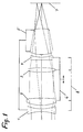
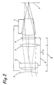
- FIG. 1 and FIG. 2 denotes an anamorphic attachment for a stationary photographic basic lens 5, which images into an image area 7.
- the attachment 8 is designed for the basic lens 5 set at a fixed distance, preferably infinity, and has on the object side a diverging axially symmetrical assembly 1 and a three-part assembly with an anamorphic effect which is arranged between the latter and the base lens 5 and is marked with 6, which in turn is on the object side from a collecting cylindrical subassembly 2, in the middle from a collecting axially symmetrical subassembly 3 and on the image side from a diverging cylindrical one Subassembly 4 exists.
- the first two assemblies 1 and 2 and the last two assemblies 3 and 4 of the anamorphic attachment complement each other to form an afocal effect group, and the angular magnification is essentially 1.
- the first 1 and third 3 complement each other Axially symmetrical assembly of the anamorphic attachment 8 to an afocal effect group with an angular magnification that corresponds to a desired anamorphic factor.
- the anamorphic attachment 8 can be assembled with the basic lens 5 set to infinity to form an overall lens and / or can be detachably connected to the basic lens 5.
- the four assemblies of the anamorphic attachment 8 are shown as single lenses, limited to the principle. So it is not a corrected example.
- the beam paths in Fig. 1 and Fig. 2 are calculated for an infinitely distant object. Behind the anamorphic attachment 8, the beam paths are afocal in both sections. Thereby it is ensured that the focal length on the image side behind the basic lens 5 matches in both sections.
Landscapes
- Physics & Mathematics (AREA)
- General Physics & Mathematics (AREA)
- Optics & Photonics (AREA)
- Lenses (AREA)
- Prostheses (AREA)
Description
- Die Erfindung betrifft einen anamorphotischen Vorsatz für ein photographisches Grundobjektiv nach dem Oberbegriff des Anspruchs 1.
- Bei anamorphotischen Vorsätzen erfordert die konstruktive Ausgestaltung der Fokussierung besondere Beachtung.
- Bei den älteren sehr verbreiteten anamorphotischen Vorsätzen, die in einem Schnitt frei von Brechkraft sind, kann zuerst das Grundobjektiv und danach der Vorsatz fokussiert werden; diese Art der Fokussierung ist schwierig und kann nur durch aufwendige Steuerkurven mechanisch erleichtert werden.
- Durch die DE-OS 34 36 913 ist ein Vorschlag bekannt geworden, eine Teilbaugruppe des anamorphotischen Vorsatzes mit dem Grundobjektiv oder einer Teilbaugruppe des Grundobjektivs gekoppelt zu verschieben, wodurch wenigstens für einen kleinen Fokussierbereich die Bildschärfe erhalten bleibt. Dieser Lösungsvorschlag ist jedoch insbesondere wegen der damit verbundenen Probleme der Korrektion der Bildfeldwölbung nicht zufriedenstellend.
- Eine verbesserte Lösung des Fokussierproblems stellt die Konstruktion des anamorphotischen Vorsatzes nach der DE-OS 36 29 438 dar, bei der durch axiale Bewegung einer Wirkungsgruppe des anamorphotischen Vorsatzes die Scharfstellung für die senkrechte und waagrechte Axialebene über den ganzen Fokussierbereich aufrechterhalten bleibt. Ein Nachteil dieser Konstruktion besteht jedoch darin, daß die Brechkraft der zweiten Baugruppe des viergliedrigen anamorphotischen Vorsatzes im Vergleich zu den übrigen Baugruppen recht stark ist und dadurch entweder ein größerer Aufwand an Linsen erforderlich wird oder die Abbildungsqualität begrenzt bleibt.
- Der Erfindung liegt die Aufgabe zugrunde, einen anamorphotischen Vorsatz zu schaffen, der bei einfachem Aufbau eine problemlose Fokussierung der Kombination von anamorphotischem Vorsatz und Grundobjektiv bei optimalen Korrektionsmöglichkeiten bietet.
- Erfindungsgemäß wird diese Aufgabe durch einen anamorphotischen Vorsatz mit den Merkmalen des Patentanspruchs 1 gelöst. Vorteilhafte Weiterbildungen des Erfindungsgedankens ergeben sich aus den Unteransprüchen.
- Bei dem erfindungsgemäßen anamorphotischen Vorsatz kann beim Fokussieren die Entfernungseinstellung des Grundobjektives unverändert bleiben. Zum Fokussieren wird entweder die erste objektseitige axialsymmetrische Baugruppe des anamorphotischen Vorsatzes oder eine darauf folgende dreiteilige Wirkungsgruppe verschoben. In beiden Fällen ist die Wirkung des Fokussierhubes in der senkrechten und waagerechten Axialebene gleich, so daß das Bild über den gesamten Fokussierbereich durch die axiale Bewegung einer einzelnen Wirkungsgruppe scharf bleibt. Der erfindungsgemäße anamorphotische Vorsatz hat den ganz wesentlichen Vorteil, daß durch die gewählte Brechkraftfolge insbesondere die Brechkraft der zweiten Baugruppe des anamorphotischen Vorsatzes merklich geringer ist. Eine vergleichende Analyse der optischen Korrigierbarkeit läßt dies sehr deutlich werden.
- Ein Ausführungsbeispiel der Erfindung wird nachfolgend anhand der anhängenden Zeichnung näher beschrieben.
- Es zeigen
- Fig. 1
- einen erfindungsgemäßen Anamorphoten im senkrechten Axialschnitt und
- Fig. 2
- den erfindungsgemäßen Anamorphoten im waagerechten Axialschnitt.
- In Fig. 1 und Fig. 2 ist mit 8 ein anamorphotischer Vorsatz für ein ortsfestes photographisches Grundobjektiv 5 markiert, das in eine Bildfläche 7 abbildet. Der Vorsatz 8 ist für das auf eine feste Entfernung, vorzugsweise Unendlich, eingestellte Grundobjektiv 5 ausgebildet und weist objektseitig eine zerstreuende axialsymmetrische Baugruppe 1 und eine zwischen dieser und dem Grundobjektiv 5 angeordnete, mit 6 markierte, dreiteilige Baugruppe mit anamorphotischer Wirkung auf, die ihrerseits objektseitig aus einer sammelnden zylindrischen Teilbaugruppe 2, in der Mitte aus einer sammelnden axialsymmetrischen Teilbaugruppe 3 und bildseitig aus einer zerstreuenden zylindrischen Teilbaugruppe 4 besteht. In einer Axialebene ergänzen sich jeweils die ersten beiden Baugruppen 1 und 2 sowie die letzten beiden Baugruppen 3 und 4 des anamorphotischen Vorsatzes zu einer afokalen Wirkungsgruppe, und die Winkelvergrößerung beträgt im wesentlichen 1. In der dazu senkrechten Axialebene ergänzen sich die erste 1 und dritte 3 axialsymmetrische Baugruppe des anamorphotischen Vorsatzes 8 zu einer afokalen Wirkungsgruppe mit einer Winkelvergrößerung, die einem gewünschten anamorphotischen Faktor entspricht. Es bildet entweder die objektseitige zerstreuende axialsymmetrische Baugruppe 1 des anamorphotischen Vorsatzes 8 oder die zwischen dieser und dem Grundobjektiv 5 angeordnete dreiteilige Baugruppe mit anamorphotischer Wirkung 6 einen Fokussierteil, wobei die jeweils andere Baugruppe 6 bzw. 1 stationär zum Grundobjektiv 5 bleibt.
- Der anamorphotische Vorsatz 8 kann mit dem auf Unendlich eingestellten Grundobjektiv 5 zu einem Gesamtobjektiv zusammengebaut und/oder mit dem Grundobjektiv 5 lösbar verbunden sein.
- In der Zeichnung Fig. 1 und Fig. 2 sind die vier Baugruppen des anamorphotischen Vorsatzes 8 in Beschränkung auf das Prinzip als Einzellinsen dargestellt. Es handelt sich also nicht um ein korrigiertes Beispiel. Die Strahlengänge in Fig. 1 und Fig. 2 sind für ein unendlich fernes Objekt gerechnet. Hinter dem anamorphotischen Vorsatz 8 sind die Strahlengänge in beiden Schnitten afokal. Dadurch ist gewährleistet, daß die bildseitige Schnittweite hinter dem Grundobjektiv 5 in beiden Schnitten übereinstimmt.
Claims (3)
- Anamorphotischer Vorsatz (8) für ein Grundobjektiv (5), welches auf eine feste Entfernung eingestellt ist, mit objektseitig einer zerstreuenden axialsymmetrischen Baugruppe (1) und einer zwischen dieser und dem Grundobjektiv angeordneten dreiteiligen anamorphotischen Baugruppe (6), welche objektseitig aus einer sammelnden zylindrischen Baugruppe (2) und an der dem Grundobjektiv zugewandten Seite aus einer sammelnden axialsymmetrischen Baugruppe (3) und einer zerstreuenden zylindrischen Baugruppe (4) besteht, und mit Mitteln zur axialen Verstellung entweder der zerstreuenden axialsymmetrischen Baugruppe (1) oder der dreiteiligen anamorphotischen Baugruppe (6) in bezug auf das Grundobjektiv (5) zur Fokussierung des aus Grundobjektiv und Vorsatz bestehenden Gesamtsystems, wobei, wenn die Fokussierung des Gesamtsystems so eingestellt ist, daß sie der festen Einstellung des Grundobjektivs (5) entspricht, in der Axialebene, in der die zylinderischen Baugruppen (2, 4) ihre maximale Wirkung haben, sich die Wirkungen der zerstreuenden axialsymmetrischen Baugruppe (1) und der sammelnden zylindrischen Baugruppe (2) und die Wirkungen der sammelnden axialsymmetrischen Baugruppe (3) und der zerstreuenden zylindrischen Baugruppe (4) jeweils kompensieren, und in der Axialebene, in der die zylinderischen Baugruppen (2, 4) keine Wirkung haben, die beiden axialsymmetrischen Baugruppen (1, 3) einen die Brennweite des Grundobjektivs (5) um den Anamorphotfaktor verkürzenden Weitwinkelvorsatz bilden, dadurch gekennzeichnet, daß die sammelnde axialsymmetrische Baugruppe (3) zwischen der sammelnden (2) und der zerstreuenden zylindrischen Baugruppe (4) angeordnet ist.
- Anamorphotischer Vorsatz nach Anspruch 1, dadurch gekennzeichnet, daß der Vorsatz (8) mit dem auf Unendlich gestellten Grundobjektiv (5) zu einem Gesamtobjektiv zusammengebaut ist.
- Anamorphotischer Vorsatz nach Anspruch 1 oder 2, dadurch gekennzeichnet, daß der Vorsatz (8) mit dem Grundobjektiv (5) lösbar verbunden ist.
Applications Claiming Priority (2)
| Application Number | Priority Date | Filing Date | Title |
|---|---|---|---|
| DE4023059A DE4023059A1 (de) | 1990-07-20 | 1990-07-20 | Anamorphotischer vorsatz fuer ein photographisches grundobjektiv |
| DE4023059 | 1990-07-20 |
Publications (2)
| Publication Number | Publication Date |
|---|---|
| EP0467281A1 EP0467281A1 (de) | 1992-01-22 |
| EP0467281B1 true EP0467281B1 (de) | 1995-12-20 |
Family
ID=6410649
Family Applications (1)
| Application Number | Title | Priority Date | Filing Date |
|---|---|---|---|
| EP91111821A Expired - Lifetime EP0467281B1 (de) | 1990-07-20 | 1991-07-16 | Anamorphotischer Vorsatz für ein photographisches Grundobjektiv |
Country Status (3)
| Country | Link |
|---|---|
| EP (1) | EP0467281B1 (de) |
| DE (2) | DE4023059A1 (de) |
| ES (1) | ES2081396T3 (de) |
Cited By (1)
| Publication number | Priority date | Publication date | Assignee | Title |
|---|---|---|---|---|
| US8174773B2 (en) | 2008-04-29 | 2012-05-08 | Carl Zeiss Ag | Anamorphotic imaging objective |
Family Cites Families (4)
| Publication number | Priority date | Publication date | Assignee | Title |
|---|---|---|---|---|
| GB852961A (en) * | 1956-09-28 | 1960-11-02 | Isco Optische Werke Gmbh | An anamorphotic and focusing attachment for an objective |
| US3041935A (en) * | 1958-08-18 | 1962-07-03 | Jan Louis Wulff Jacobsen | Anamorphotic lens system |
| JPS4974954A (de) * | 1972-11-17 | 1974-07-19 | ||
| DE3629438A1 (de) * | 1986-08-29 | 1988-04-07 | Isco Optic Gmbh | Anamorphotischer vorsatz fuer ein photographisches grundobjektiv |
-
1990
- 1990-07-20 DE DE4023059A patent/DE4023059A1/de not_active Withdrawn
-
1991
- 1991-07-16 DE DE59107108T patent/DE59107108D1/de not_active Expired - Fee Related
- 1991-07-16 EP EP91111821A patent/EP0467281B1/de not_active Expired - Lifetime
- 1991-07-16 ES ES91111821T patent/ES2081396T3/es not_active Expired - Lifetime
Cited By (1)
| Publication number | Priority date | Publication date | Assignee | Title |
|---|---|---|---|---|
| US8174773B2 (en) | 2008-04-29 | 2012-05-08 | Carl Zeiss Ag | Anamorphotic imaging objective |
Also Published As
| Publication number | Publication date |
|---|---|
| DE4023059A1 (de) | 1992-01-23 |
| EP0467281A1 (de) | 1992-01-22 |
| ES2081396T3 (es) | 1996-03-01 |
| DE59107108D1 (de) | 1996-02-01 |
Similar Documents
| Publication | Publication Date | Title |
|---|---|---|
| DE3909755C2 (de) | Varioobjektiv für Kompaktkameras | |
| DE3802725C2 (de) | ||
| DE19508278C2 (de) | Varioobjektiv | |
| DE3844239C2 (de) | Varioobjektiv | |
| DE4032051C2 (de) | Objektiv langer Brennweite | |
| DE19723226A1 (de) | Zoom-Linsensystem | |
| DE2603455A1 (de) | Afokaler, pankratischer fernrohrvorsatz | |
| DE2513027A1 (de) | Automatische fokussiereinrichtung | |
| EP1555565A1 (de) | Vorrichtung zur optischen Strahltransformation einer linearen Anordnung mehrerer Lichtquellen | |
| DE102019118264A1 (de) | Beleuchtungsvorrichtung für ein Kraftfahrzeug, insbesondere hochauflösender Scheinwerfer | |
| DE3221184A1 (de) | Optisches suchersystem mit dioptrien-korrekturverstellung | |
| DE3329040A1 (de) | Verfahren und einrichtung zur lichtstrahlabtastung | |
| DE2413473C2 (de) | Weitwinkelobjektiv vom Typ umgekehrter Teleobjektive | |
| DE3027558C2 (de) | Auf nahe Objektive scharf einstellbares Varioobjektiv | |
| DE4104557A1 (de) | Reellbildsucher | |
| DE4424131B4 (de) | Einrichtung zum Erfassen der Scharfeinstellung eines Objektivs | |
| EP1574808B1 (de) | Zielfernrohr | |
| DE3644124C2 (de) | ||
| DE2357547B2 (de) | Anamorphotisches Objektiv | |
| DE2058675A1 (de) | Bildumlenksystem fuer Stereomikroskope | |
| DE102012202637A1 (de) | Projektionskopf für einen Laserprojektor | |
| DE2631831A1 (de) | Abtasteinrichtung fuer strahlung | |
| DE4106534C2 (de) | System von Teleobjektiven | |
| DE3149852A1 (de) | Varioobjektiv mit rueckseitig angeordneter blende | |
| EP0467281A1 (de) | Anamorphotischer Vorsatz für ein photographisches Grundobjektiv |
Legal Events
| Date | Code | Title | Description |
|---|---|---|---|
| PUAI | Public reference made under article 153(3) epc to a published international application that has entered the european phase |
Free format text: ORIGINAL CODE: 0009012 |
|
| AK | Designated contracting states |
Kind code of ref document: A1 Designated state(s): AT BE CH DE DK ES FR GB GR IT LI LU NL SE |
|
| RBV | Designated contracting states (corrected) |
Designated state(s): DE ES FR GB IT |
|
| 17P | Request for examination filed |
Effective date: 19920824 |
|
| 17Q | First examination report despatched |
Effective date: 19940318 |
|
| GRAA | (expected) grant |
Free format text: ORIGINAL CODE: 0009210 |
|
| AK | Designated contracting states |
Kind code of ref document: B1 Designated state(s): DE ES FR GB IT |
|
| ITF | It: translation for a ep patent filed | ||
| REF | Corresponds to: |
Ref document number: 59107108 Country of ref document: DE Date of ref document: 19960201 |
|
| GBT | Gb: translation of ep patent filed (gb section 77(6)(a)/1977) |
Effective date: 19960122 |
|
| ET | Fr: translation filed | ||
| REG | Reference to a national code |
Ref country code: ES Ref legal event code: FG2A Ref document number: 2081396 Country of ref document: ES Kind code of ref document: T3 |
|
| PGFP | Annual fee paid to national office [announced via postgrant information from national office to epo] |
Ref country code: ES Payment date: 19960709 Year of fee payment: 6 |
|
| PLBE | No opposition filed within time limit |
Free format text: ORIGINAL CODE: 0009261 |
|
| STAA | Information on the status of an ep patent application or granted ep patent |
Free format text: STATUS: NO OPPOSITION FILED WITHIN TIME LIMIT |
|
| 26N | No opposition filed | ||
| PG25 | Lapsed in a contracting state [announced via postgrant information from national office to epo] |
Ref country code: ES Free format text: LAPSE BECAUSE OF EXPIRATION OF PROTECTION Effective date: 19970717 |
|
| PGFP | Annual fee paid to national office [announced via postgrant information from national office to epo] |
Ref country code: DE Payment date: 19980702 Year of fee payment: 8 |
|
| PGFP | Annual fee paid to national office [announced via postgrant information from national office to epo] |
Ref country code: GB Payment date: 19980707 Year of fee payment: 8 |
|
| PGFP | Annual fee paid to national office [announced via postgrant information from national office to epo] |
Ref country code: FR Payment date: 19980729 Year of fee payment: 8 |
|
| PG25 | Lapsed in a contracting state [announced via postgrant information from national office to epo] |
Ref country code: GB Free format text: LAPSE BECAUSE OF NON-PAYMENT OF DUE FEES Effective date: 19990716 |
|
| PG25 | Lapsed in a contracting state [announced via postgrant information from national office to epo] |
Ref country code: FR Free format text: THE PATENT HAS BEEN ANNULLED BY A DECISION OF A NATIONAL AUTHORITY Effective date: 19990731 |
|
| GBPC | Gb: european patent ceased through non-payment of renewal fee |
Effective date: 19990716 |
|
| PG25 | Lapsed in a contracting state [announced via postgrant information from national office to epo] |
Ref country code: DE Free format text: LAPSE BECAUSE OF NON-PAYMENT OF DUE FEES Effective date: 20000503 |
|
| REG | Reference to a national code |
Ref country code: FR Ref legal event code: ST |
|
| REG | Reference to a national code |
Ref country code: ES Ref legal event code: FD2A Effective date: 20010201 |
|
| PG25 | Lapsed in a contracting state [announced via postgrant information from national office to epo] |
Ref country code: IT Free format text: LAPSE BECAUSE OF NON-PAYMENT OF DUE FEES Effective date: 20050716 |