EP0466043A2 - Installation de distribution comprenant au moins deux rangées d'appareils électriques de type étroit - Google Patents
Installation de distribution comprenant au moins deux rangées d'appareils électriques de type étroit Download PDFInfo
- Publication number
- EP0466043A2 EP0466043A2 EP91111203A EP91111203A EP0466043A2 EP 0466043 A2 EP0466043 A2 EP 0466043A2 EP 91111203 A EP91111203 A EP 91111203A EP 91111203 A EP91111203 A EP 91111203A EP 0466043 A2 EP0466043 A2 EP 0466043A2
- Authority
- EP
- European Patent Office
- Prior art keywords
- plug
- distribution system
- busbar
- busbars
- contacting
- Prior art date
- Legal status (The legal status is an assumption and is not a legal conclusion. Google has not performed a legal analysis and makes no representation as to the accuracy of the status listed.)
- Granted
Links
Images

Classifications
-
- H—ELECTRICITY
- H02—GENERATION; CONVERSION OR DISTRIBUTION OF ELECTRIC POWER
- H02B—BOARDS, SUBSTATIONS OR SWITCHING ARRANGEMENTS FOR THE SUPPLY OR DISTRIBUTION OF ELECTRIC POWER
- H02B1/00—Frameworks, boards, panels, desks, casings; Details of substations or switching arrangements
- H02B1/20—Bus-bar or other wiring layouts, e.g. in cubicles, in switchyards
- H02B1/205—Bus-bar or other wiring layouts, e.g. in cubicles, in switchyards for connecting electrical apparatus mounted side by side on a rail
-
- H—ELECTRICITY
- H02—GENERATION; CONVERSION OR DISTRIBUTION OF ELECTRIC POWER
- H02B—BOARDS, SUBSTATIONS OR SWITCHING ARRANGEMENTS FOR THE SUPPLY OR DISTRIBUTION OF ELECTRIC POWER
- H02B1/00—Frameworks, boards, panels, desks, casings; Details of substations or switching arrangements
- H02B1/015—Boards, panels, desks; Parts thereof or accessories therefor
- H02B1/04—Mounting thereon of switches or of other devices in general, the switch or device having, or being without, casing
- H02B1/056—Mounting on plugboards
Definitions
- the invention relates to a distribution system with at least two, preferably horizontally running, arranged one below the other, each mounted on a support member rows of electrical installation devices in narrow construction, the power supply via an insulating supported busbar system and associated plug-in elements.
- a busbar block has become known, as can be found in DE-GM 87 00 153.
- Such a three-pole busbar block serves to supply switching devices with voltage, which can therefore all be connected simultaneously to the current phases assigned to them.
- the individual busbars which are arranged and held - insulated from one another - in a multi-walled box profile made of insulating material, have connection straps at regular intervals, which are inserted directly into the screw connection sockets from the connection side of the individual installation devices.
- connection technology is, especially when it comes to distribution systems with a larger number of installation devices, quite time-saving and also space-saving.
- a disadvantage here can be seen in the fact that in the case of so-called post-installations, the entire access-side wiring of all installation devices arranged on a mounting rail and connected to the busbar block must be released in order to be able to insert the additional installation devices into the system. The same applies in the event that individual installation devices have to be replaced, be it because they are defective, or if, for example, instead of an installation device with a lower nominal output, one with a higher nominal output is to be used.
- EP 0 229 590 A1 A low-voltage distribution in which the disadvantage just mentioned is avoided can be found in EP 0 229 590 A1.
- the installation devices to be accommodated near their underside or their attachment level with dovetail-shaped recesses, into each of which a so-called plug tulip, ie a jaw-like contact member, and a locking slide can be inserted.
- Both this recess and the locking slide are provided with recesses which are provided transversely to the course of the recess and in which lateral guide plates of the plug-in tulip can engage.
- these plug-in tulips can be attached to the installation device in different positions and fixed by means of the locking slide.
- the plug-in tulips themselves are connected to flexible lines which can be inserted into a connection contact point of the respective installation device and fastened in a contacting manner therein.
- These plug-in tulips now contact with a rail system that is held in a plug-in base.
- This construction is complex in terms of the mounting and contacting connection of the plug-in tulips, both in terms of the required parts and the need to bring these plug-in tulips into the desired position, which - as already stated above - usually only can or will happen at the installation site.
- the present invention has for its object to provide a distribution system for two or more rows of installation devices to be accommodated with a power supply via busbars, which avoids the disadvantages described and in terms of the required parts and assembly effort as inexpensively and as possible can be produced in a space-saving manner.
- the distribution system to be created should be designed in such a way that it is easy to supplement the existing installation devices or to replace existing installation devices without temporarily removing a busbar block or at least having to loosen the screw connections of adjacent installation devices. to have to carry out manipulations on the individual installation devices at the installation site, if one does not make a clamp connection, and finally to avoid having to equip each individual row of installation devices with separate power supplies.
- Such a construction is particularly useful in those cases in which not only two, but several or even quite a number of rows of installation devices are to be arranged with one another within a distribution system and to be supplied with power supplies. This is because in this case - at least in the case of distribution systems with a "normal”, ie not excessively large width - only a single distribution base is required, the individual busbars of which must be connected to a phase feed at only one point, regardless of how large the number of rows of installation devices one below the other. In addition, it is possible without major difficulties to remove each of the installation devices from each row and to replace or replace them with another device.
- this solution is at the expense of the overall height, which, however, can be tolerated by making installation easier at the installation site and, as already mentioned, by simply replacing individual installation devices.
- Such a distribution system can be largely prefabricated in the factory, including the connection of the individual busbars with connections for the power supply.
- An expedient embodiment of the concept of the invention can be seen in providing the receiving pockets provided in the distributor base for receiving the busbars on their side facing the installation devices to be contacted with a slot-shaped pocket opening serving for the passage of the plug-in elements and which is narrower than the remaining pocket cross section.
- busbars inserted into the receiving pockets can be fixed in their position and at the same time secured against escaping.
- the always desired touch protection is improved by a narrowed pocket opening.
- the free ends of the U-shaped or C-shaped cross-sectional contour can be at a distance from one another which is at least slightly smaller than the width or thickness of a plug element which can be inserted between these free ends or legs of the busbar designed in this way.
- a clamping effect can be achieved, which is very desirable, but it is also advantageous that the design of the individual plug-in elements can be made simpler. H. no fork-shaped, resilient clamping jaws or the like are required.
- busbars A special design of the busbars that is advantageous in terms of assembly and possibly also material savings can be seen in the proposal to produce them from a sheet metal material that is flat in the initial shape and to shape this starting material into a heart-shaped cross-sectional profile, with both lateral edge areas of the initial shape into the interior of the profile end directed and have a distance from each other.
- Such busbars can be laterally compressed to a sufficient extent during assembly with the associated distributor base, so that they can be inserted into the pockets of a distributor base through a slot-shaped pocket opening with a pocket cross-section narrowed towards the outside. With a corresponding dimensioning of the busbars it can be achieved that they abut self-adherently on the side walls of said pockets inside.
- Another advantage of busbars designed in this way is that they have a comparatively large surface area, as a result of which a more favorable heat dissipation effect can be achieved.
- plug-in elements for the contacting connection between an installation device and an associated busbar.
- These plug-in elements can have a largely rigid, approximately angled shape in the region of their longitudinal center, it being provided that they be inserted with one free end into the contact connection point of the associated installation device and with their other free end connected to the corresponding busbar. After the installation of the individual installation devices, such plug-in elements can be attached to these and the associated busbars and, if necessary, removed from them again without impairing neighboring devices or their plug-in elements in any way.
- these plug-in elements can be produced from a starting material that is round or square in cross-section, the free ends being deformed into flattened or tapered contacting areas.
- the plug-in elements can be produced as an angular stamped parts from sheet metal or strip material, one leg of which is then bent by approximately 90 ° while twisting the corner area. With such plug-in elements, it is not necessary to flatten the contacting areas.
- the essential extension planes of their flattened or planar contacting areas run perpendicular to one another, in such a way that - in the assembled position - the contacting area supplied to the installation device runs parallel to the mounting plane of the installation device, whereas the a track supplied contacting area extends parallel to the side walls of the installation device.
- Such an arrangement of the flattened or flat contacting areas of the individual plug-in elements favors their assembly and, if necessary, their disassembly in the event of the need to replace an installation device.
- installation devices whose shape and connection option differs from the other installation devices must also be accommodated.
- This can be, for example, bell transformers, timers for staircase lighting, functional elements for an alarm system or similar functional elements.
- plug-in elements in the form of box-shaped screw connection terminals are recommended, in accordance with an expedient further training suggestion, each of which is provided with a knife contact for contacting a busbar.
- One end of an easily deformable connecting wire or a flexible connecting wire can now be inserted into the screw terminal of such a plug element and fastened in contacting manner therein.
- the other end of this wire or this strand is to be fed to the contact connection point of an installation device of any design, ie a simple possibility of contacting said busbars is also provided for installation devices deviating from a standard in terms of design.
- the individual busbars of a distribution system require a current feed, ie a contacting connection with a phase of the power network supplied to the distribution system.
- This current can be fed in, for example, via installation devices in the form of circuit breakers.
- this would mean that a complete series of circuit breakers would have to be used to supply all the individual busbars with voltage. This is quite complex in terms of device requirements, especially when the number of rows of installation devices in a distribution system is not very large.
- jumpers for the power supply of the busbar system each of which consists of a connection point preferably formed in the form of a box-shaped screw connection terminal, the latter being connected in one piece or in a contacting manner to a laterally extending, rail-like bridge member which run out of at least two knife contacts for contacting a corresponding number of busbars.
- at least three knife contacts extend from this bridge member, which are spaced apart and positioned such that they are able to contact every third busbar of the busbar system. In this way, it is possible to equip at least nine busbars with a power supply with a total of three jumpers.
- Such jumpers are, in terms of equipment costs, cheaper than the use of circuit breakers for the feed, and the space required within the distribution system is also less.
- plug-in bridges just mentioned can be seen in the proposal to encase them all around with insulating material, with the exception of the intended contacting areas of the connection point and the knife contacts. In this way, protection against accidental contact is provided in any case, which is also advantageous if these jumpers are covered by a corresponding insulating material plate or the like within the distribution system.
- the current-conducting parts of such a jumper can, for example, be cut to length in one piece from an appropriately shaped extrusion. According to an advantageous design proposal, it can also be provided to produce both the connection point and the bridge member, and finally the knife contacts emanating from this bridge member, from a single metal strip, for example from a copper or an aluminum strip, the latter of which is angled and accordingly folded and then overmolded with an insulating jacket.
- Such jumpers designed at least when the need for jumpers is not excessive, can ultimately be cheaper to manufacture than the use of a corresponding extruded profile. The latter is because the width of the individual jumpers only has to be relatively small, and one hundred or even more of jumper parts can be made from a two-meter-long extruded profile - by cutting to length.
- Distribution systems of the type in question can certainly have different widths.
- the number of installation devices that can be arranged in a row can be doubled or even further increased.
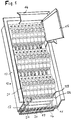
- FIG. 1 illustrates a distribution system 12 which is cut off towards the bottom and which consists of a housing 13 to be inserted into masonry, a frame 14 (shown cut off) and a front door 15 (also shown cut off).
- a distributor base 16 with laterally projecting, flange-like profile formations 17 and 18 is arranged and fastened.
- This distributor socket 16 is formed by an extruded profile made of insulating material and has a plurality of — in the present case nine — vertical receiving pockets 19.
- a busbar 20 is arranged in each of these receiving pockets 19.
- flange-like profile formations 17 and 18 (not visible in this illustration) are attached supporting members, on which, as can be seen from this illustration, three rows of installation devices 21 are now held in a latching manner.
- the contacting connection between the individual installation devices 21 and the busbars 20 takes place in each case by means of a separate, approximately angularly bent plug element 22, which can be plugged together at one end into a contact connection point 23 of the installation device 21 and at the other end with the associated busbar (20) is.
- three plug-in bridges 24 are used to supply power to the individual busbars 20 of the busbar system, all of which are of completely identical design, but which are mounted laterally offset from one another. Further features of these jumpers 24 will be explained below.
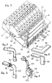
- FIG. 1 The row of installation devices 21 at the bottom in FIG. 1 is illustrated again in FIG. 2 on a somewhat enlarged scale.
- the installation devices 21 are, however, not immediately recognizable, snapped onto the support member 25 and thus held next to one another.
- This support member 25 is in turn fastened to the laterally projecting, flange-like profile formations 17 and 18 of the distributor base 16 by means of screw elements 26.
- the individual installation devices 21 are connected in contact with the busbars 20 via the plug-in elements 22 already mentioned, whereby - as already explained above - one end of the plug-in element 22 is inserted into the contact connection point 23 of the associated installation device 21 and the other end of the plug-in element 22 with the associated one Busbar 20 is plugged together.
- these busbars have an approximately U-shaped cross-sectional profile. The latter end of a plug-in element 22 is inserted between the two free legs of this profile.
- each of the busbars 20 contacts a plug element 22 in each of the rows of installation devices.
- the jumpers 24 already mentioned each have at their one longitudinal end a connection point in the form of a box-shaped screw terminal 27, in which a cable feeding the current can be fastened in a contacting manner.
- Three knife contacts 28, 29 and 30 protrude from the broad sides of the plug-in jumpers 24 facing away from the screw-type connection terminals 27 and can be adhesively inserted into correspondingly assigned busbars 20.
- the distance between the individual knife contacts 28, 29 and 30 is selected such that a first and then every third busbar (20) can be contacted.
- a total of nine power rails 20 are supplied with a mains voltage from the three jumpers 24.
- FIG. 3 Such a plug-in member 22 is illustrated in FIG. 3 in a perspective view. It can be seen that this plug-in element 22 has an angular shape with two legs 31 and 32, which have a round cross section in their longitudinal regions which are directed towards one another and are connected to one another in the corner region. The free end of the leg 31 also has a round cross-sectional contour, but the outside diameter is smaller than the previous longitudinal region of this leg 31.
- the free end of the leg 32 has a (for example hammered) flattening, which tapers a little in thickness towards the extreme end and whose thickness is dimensioned in such a way that this flattened, approximately spade-shaped free end of leg 32 can be adhesively inserted into a busbar 20, as can be seen in FIG .
- a (for example hammered) flattening which tapers a little in thickness towards the extreme end and whose thickness is dimensioned in such a way that this flattened, approximately spade-shaped free end of leg 32 can be adhesively inserted into a busbar 20, as can be seen in FIG .
- FIG. 4 shows, again in perspective, a plug-in element 33, the starting form of which is again formed by a round material and angled approximately in the longitudinal center. Accordingly, this plug-in member 33 also has two legs 34 and 35, one of which (34) is shown separated in sections to illustrate the round cross-sectional contour which is provided with the number 36. In contrast to the plug-in element 32 shown in FIG. 3, this plug-in element 33 has flats on both free leg ends, both of which serve as contacting areas. It is characteristic of this plug-in member 33 that the essential extension planes of the flattened contact areas run perpendicular to each other, in such a way that - in the assembled position of the plug-in member 33 - the contacting area to be supplied to an installation device 21 (see FIGS. 1 or 2) is parallel to the mounting plane of the installation device 21 runs, whereas the contacting area to be supplied to a busbar 20 (see again FIGS. 1 or 2) extends parallel to the side walls of the installation devices 21.
- FIG. 5 illustrates in two individual representations a plug-in member 37, the starting form of which is formed by an angular stamped part made of sheet metal or strip material with the legs 38 and 39, see the representation above in the drawing 5.
- This plug-in member 37, with legs 38 and 39 initially running completely evenly, is then deformed in one operation, one leg 39 being bent by twisting the corner region by approximately 90 °, see the lower illustration in FIG. 5 there is again a shape with two contacting areas, the essential extension planes of which are located practically the same as is the case with the plug element 33 according to FIG. 4, see the explanations above.
- FIGS. 1 and 2 illustrate installation devices with different designs in addition to installation devices in a narrow construction and with connection points that are always the same, as can be seen in FIGS. 1 and 2, installation devices with different designs can also be arranged within a distribution system, the connection points of which also often are located differently than with the installation devices mentioned in narrow construction.
- These installation devices which differ from the other installation devices in terms of their design, require a power supply, but the plug-in elements according to FIGS. 3 to 5 explained above are not suitable for this.
- FIG . 6 illustrates a solution that is suitable for such needs. This shows a plug-in element 40 in the form of a box-shaped screw terminal, from which a knife contact 41 originates.
- This knife contact 41 is integrally connected to a screw terminal part 42, the latter being surrounded by an insulating jacket 43.
- a strand 44 can be fastened in a contacting manner, which can be provided, for example, with a cable lug 45 at its free end.
- the latter is used to connect to an installation device with a connection point located differently than is the case with the installation devices 21 in a narrow construction.
- this plug-in element 40 can be plugged together in contact with a busbar 20 (see FIGS. 1 and 2), in the same way as is provided for the plug-in elements according to FIGS. 3 to 5.
- FIG. 7 shows a jumper 24, as has already been described in connection with the explanations for Figure 2. It has an essentially rail-shaped design and contains at its one longitudinal end the box-shaped screw terminal 27 already mentioned above. From the side of the rail-shaped shape facing away from the screw terminal 27, the knife contacts 28, 29 and 30 also mentioned go out, which in this The illustration is better recognizable than in FIG. 2. It should also be mentioned that the knife contacts 28, 29 and 30 mentioned are not insulated, but the rest of the longitudinal region of this jumper 24 is surrounded by insulation all around, except for the inside of the screw terminal 27. From It is of interest how the metallic body is designed without the insulating sheath mentioned, because this cannot be seen in FIG. 7; but probably the figure 8 .
- This extruded profile 46 has an essentially E-shaped shape, namely a long connecting leg 47, from which short legs 48, 49 and 50 projecting vertically. These latter legs 48 to 50 represent the knife contacts which are numbered 28 to 30 in FIG.
- a shaped area 51 with a rectangular cross section is provided with an opening 52 arranged therein.
- one or more threaded bores are made at right angles to the opening 52 on the rectangular shaped region 51, in the present case the threaded bores 53 and 54 to be able to clamp contacting inserted cable into the opening 52.
- a longitudinal region separated from the extruded profile 46, as can be seen in FIG. 8, is then to be encased or encapsulated with an insulating material, as has already been explained for the plug-in bridge 24 according to FIG. 7, that is to say the short legs 48, 49 and 50 are not encased and the end faces of the rectangular shaped area 51 must also remain free of plastic encapsulation at least in the area of the opening 52.
- the latter also applies to the threaded bores 53 and 54, which, however, can be surrounded by pipe socket-like collars, as can be seen in FIG. 7. The latter can not only serve as protection against contact, but also as a guide for a screwing tool.
- FIG. 9 illustrates a longitudinal section through a jumper 55, which is shown in perspective in the rest.
- This plug-in bridge differs from the plug-in bridge 24 shown in FIG. 7 and its metallic insert in the form of the extruded profile 46 according to FIG. 8 by a different design of the metallic insert.
- This consists namely of a metal band 56 which is angled and folded as shown, the longitudinal course of which begins at the end region 57 on the right in the illustration, which can be clearly seen from the illustration.
- a plug-in contact 58 is formed by largely folding it together, after a longer section in the plane of the end region 57, a further plug-in contact 59 is formed and finally a third plug-in contact 60.
- a contact connection region 61 is formed, which with a or two passages 62 and screw threads incorporated therein.
- a type of box terminal is formed, which is used to connect a current-carrying line.
- a connection screw 63 can be seen in this box area, which is equipped with a roof-shaped thrust washer 64 on its area located inside the box.
- This metallic structure made of the metal strip 56 is extrusion-coated with an insulating material 65, as shown, but the plug contacts 58, 59 and 60 mentioned remain free. It is needless to say that the front ends of the box-like contact connection area 61 must also be free and accessible.
- FIG. 10 shows a perspective view of a busbar 66 which, unlike the busbars in FIGS. 1 and 2, does not form a cross-sectional profile that is rigid in itself. Rather, this busbar 66 is formed from a flat sheet metal material in the initial shape, in such a way that it has an approximately heart-shaped cross-sectional profile. In this case, both lateral edge areas 67 and 68 of the originally flat initial shape end in such a way that they are directed into the interior of the profile and are apart from one another.
- Such a busbar (66) is able to spring apart to a certain extent, namely when a knife contact is inserted into the remaining longitudinal slot. In the same way, this busbar can also be compressed to a certain extent in such a way that it can be inserted into a receiving pocket of a distributor base which is narrowed on the access side.
- FIG. 11 . 1 and 2 The arrangement of a busbar, as has just been explained and shown in FIG. 10, within a receiving pocket of a distributor base is shown in FIG . 11 . 1 and 2, this represents a region of a distributor base 69 which is broken off on both sides.
- this distributor base 69 receiving pockets 70, 71, 72 and, to the left and right thereof, further receiving pockets are formed. Looking upward in the illustration, these receiving pockets 70 to 72 have slit-shaped pocket openings 73, 74 and 75 which, as can be seen, are narrowed relative to the remaining pocket cross section.
Landscapes
- Engineering & Computer Science (AREA)
- Power Engineering (AREA)
- Connector Housings Or Holding Contact Members (AREA)
- Installation Of Bus-Bars (AREA)
- Coupling Device And Connection With Printed Circuit (AREA)
- Housings And Mounting Of Transformers (AREA)
Applications Claiming Priority (2)
| Application Number | Priority Date | Filing Date | Title |
|---|---|---|---|
| DE4021826 | 1990-07-09 | ||
| DE4021826A DE4021826C2 (de) | 1990-07-09 | 1990-07-09 | Verteileranlage mit wenigstens zwei untereinander angeordneten Reihen von elektrischen Installationsgeräten in Schmalbauweise |
Publications (3)
| Publication Number | Publication Date |
|---|---|
| EP0466043A2 true EP0466043A2 (fr) | 1992-01-15 |
| EP0466043A3 EP0466043A3 (en) | 1992-02-12 |
| EP0466043B1 EP0466043B1 (fr) | 1994-06-01 |
Family
ID=6409950
Family Applications (1)
| Application Number | Title | Priority Date | Filing Date |
|---|---|---|---|
| EP91111203A Expired - Lifetime EP0466043B1 (fr) | 1990-07-09 | 1991-07-05 | Installation de distribution comprenant au moins deux rangées d'appareils électriques de type étroit |
Country Status (3)
| Country | Link |
|---|---|
| EP (1) | EP0466043B1 (fr) |
| AT (1) | ATE106626T1 (fr) |
| DE (2) | DE4021826C2 (fr) |
Cited By (6)
| Publication number | Priority date | Publication date | Assignee | Title |
|---|---|---|---|---|
| EP0748013A1 (fr) * | 1995-06-07 | 1996-12-11 | Schneider Electric Sa | Dispositif d'assemblage et de liaison électrique d'appareils modulaires tels des disjoncteurs ou analogues |
| NL1008374C2 (nl) * | 1998-02-20 | 1999-08-24 | Holec Holland Nv | Verdeelinrichting voor distributie van elektrische energie over een installatie. |
| WO2000062386A1 (fr) * | 1999-04-12 | 2000-10-19 | Siemens Aktiengesellschaft | Groupe d'appareils de commutation comportant un systeme de barres de distribution pourvu d'un encapsulage d'isolation |
| EP1777789A1 (fr) * | 2005-10-20 | 2007-04-25 | Weidmüller Interface GmbH & Co. KG | Unité d'installation électrique prémontée |
| FR2905530A1 (fr) * | 2006-08-30 | 2008-03-07 | Auxel Sa | Dispositif de distribution electrique vers des rangees d'appareils. |
| EP2834892B1 (fr) * | 2012-04-06 | 2021-01-06 | Labinal, LLC | Adaptateur de disjoncteur pour panneau de disjoncteurs enfichables |
Families Citing this family (3)
| Publication number | Priority date | Publication date | Assignee | Title |
|---|---|---|---|---|
| DE19639400B4 (de) * | 1996-09-25 | 2008-09-04 | Siemens Ag | System zum Verschienen mit flexiblen isoliergekapselten Stromschienen |
| DE19639401B4 (de) * | 1996-09-25 | 2008-09-11 | Siemens Ag | System zum Verschienen von Installationsgeräten, insbesondere von Reiheneinbaugeräten |
| DE10030610A1 (de) * | 2000-06-21 | 2002-01-03 | Abb Patent Gmbh | Installationsverteiler |
Citations (3)
| Publication number | Priority date | Publication date | Assignee | Title |
|---|---|---|---|---|
| FR2438359A1 (fr) * | 1978-10-07 | 1980-04-30 | Bbc Brown Boveri & Cie | Systeme a barres omnibus de connexion de materiels electriques encastres d'installation domestique |
| EP0063970A1 (fr) * | 1981-04-22 | 1982-11-03 | Merlin Gerin | Jeu de barre d'alimentation pour appareillage modulaire d'un coffret électrique |
| EP0109881A1 (fr) * | 1982-11-08 | 1984-05-30 | Merlin Gerin | Rail profile de fixation d'appareillage pour coffet ou tableau électrique de distribution à basse tension |
Family Cites Families (10)
| Publication number | Priority date | Publication date | Assignee | Title |
|---|---|---|---|---|
| DE1855146U (de) * | 1962-03-16 | 1962-07-19 | Rudolf Reich | Isolierstoff-sicherungshauptverteiler. |
| DE1907680A1 (de) * | 1969-02-15 | 1970-08-20 | Bbc Brown Boveri & Cie | Geraetragplatte fuer den Einbau in Verteilungen |
| DE7442827U (de) * | 1974-12-21 | 1975-04-17 | Brown Boveri & Cie Ag | Adaptersystem für Phasenschienen |
| DE2646123C2 (de) * | 1976-10-13 | 1985-03-07 | Brown, Boveri & Cie Ag, 6800 Mannheim | Tragplatte zur Halterung von elektrischen Installationsgeräten |
| DE2741037C3 (de) * | 1977-09-12 | 1981-02-05 | Siemens Ag, 1000 Berlin Und 8000 Muenchen | Tragplatte für aufschnappbare Installationsgeräte |
| DE3111801A1 (de) * | 1981-03-25 | 1982-10-14 | Siemens AG, 1000 Berlin und 8000 München | Trageinrichtung zur halterung von installationsgeraeten |
| DE3238483A1 (de) * | 1982-09-02 | 1984-03-08 | BBC Aktiengesellschaft Brown, Boveri & Cie., 5401 Baden, Aargau | Sammelschienensystem |
| ES2013259B3 (es) * | 1985-12-14 | 1990-05-01 | Cmc Carl Maier + Cie Ag | Repartidor de baja tension |
| DE8700153U1 (fr) * | 1987-01-03 | 1987-02-19 | Brown, Boveri & Cie Ag, 6800 Mannheim, De | |
| DE8804507U1 (fr) * | 1988-04-06 | 1988-05-19 | Rittal-Werk Rudolf Loh Gmbh & Co Kg, 6348 Herborn, De |
-
1990
- 1990-07-09 DE DE4021826A patent/DE4021826C2/de not_active Expired - Fee Related
-
1991
- 1991-07-05 EP EP91111203A patent/EP0466043B1/fr not_active Expired - Lifetime
- 1991-07-05 DE DE59101771T patent/DE59101771D1/de not_active Expired - Fee Related
- 1991-07-05 AT AT91111203T patent/ATE106626T1/de not_active IP Right Cessation
Patent Citations (3)
| Publication number | Priority date | Publication date | Assignee | Title |
|---|---|---|---|---|
| FR2438359A1 (fr) * | 1978-10-07 | 1980-04-30 | Bbc Brown Boveri & Cie | Systeme a barres omnibus de connexion de materiels electriques encastres d'installation domestique |
| EP0063970A1 (fr) * | 1981-04-22 | 1982-11-03 | Merlin Gerin | Jeu de barre d'alimentation pour appareillage modulaire d'un coffret électrique |
| EP0109881A1 (fr) * | 1982-11-08 | 1984-05-30 | Merlin Gerin | Rail profile de fixation d'appareillage pour coffet ou tableau électrique de distribution à basse tension |
Cited By (9)
| Publication number | Priority date | Publication date | Assignee | Title |
|---|---|---|---|---|
| EP0748013A1 (fr) * | 1995-06-07 | 1996-12-11 | Schneider Electric Sa | Dispositif d'assemblage et de liaison électrique d'appareils modulaires tels des disjoncteurs ou analogues |
| FR2735290A1 (fr) * | 1995-06-07 | 1996-12-13 | Schneider Electric Sa | Dispositif d'assemblage et de liaison electrique d'appareils modulaires tels des disjoncteurs ou analogues |
| US5745338A (en) * | 1995-06-07 | 1998-04-28 | Schneider Electric S.A. | Device for assembly and electrical connection of modular apparatuses such as circuit breakers or similar |
| NL1008374C2 (nl) * | 1998-02-20 | 1999-08-24 | Holec Holland Nv | Verdeelinrichting voor distributie van elektrische energie over een installatie. |
| EP0938175A1 (fr) * | 1998-02-20 | 1999-08-25 | Holec Holland N.V. | Equipement de distribution d'energie electrique |
| WO2000062386A1 (fr) * | 1999-04-12 | 2000-10-19 | Siemens Aktiengesellschaft | Groupe d'appareils de commutation comportant un systeme de barres de distribution pourvu d'un encapsulage d'isolation |
| EP1777789A1 (fr) * | 2005-10-20 | 2007-04-25 | Weidmüller Interface GmbH & Co. KG | Unité d'installation électrique prémontée |
| FR2905530A1 (fr) * | 2006-08-30 | 2008-03-07 | Auxel Sa | Dispositif de distribution electrique vers des rangees d'appareils. |
| EP2834892B1 (fr) * | 2012-04-06 | 2021-01-06 | Labinal, LLC | Adaptateur de disjoncteur pour panneau de disjoncteurs enfichables |
Also Published As
| Publication number | Publication date |
|---|---|
| DE4021826A1 (de) | 1992-01-16 |
| DE59101771D1 (de) | 1994-07-07 |
| DE4021826C2 (de) | 1999-07-29 |
| EP0466043B1 (fr) | 1994-06-01 |
| EP0466043A3 (en) | 1992-02-12 |
| ATE106626T1 (de) | 1994-06-15 |
Similar Documents
| Publication | Publication Date | Title |
|---|---|---|
| EP1117162B1 (fr) | Système de barres omnibus et ensemble de connexions pour connecter les barres aux bornes d'un appareil d'installation | |
| DE3621268C2 (de) | Dreiphasig gekapselte, gasisolierte Schaltanlage | |
| DE10251863B4 (de) | Stromverteilerkasten und Leistungsgerätemodul | |
| DE4021825C2 (de) | Verteileranlage mit auf einer Tragschiene anordenbaren Installationsgeräten in Schmalbauweise | |
| EP0639877B1 (fr) | Dispositif pour alimenter en énergie électrique au moins un appareil d'installation électrique | |
| EP2559107B1 (fr) | Borne de connexion de conducteur principal | |
| DE4021824A1 (de) | Verteileranlage mit auf einem tragorgan aneinanderreihbaren elektrischen installationsgeraeten in schmalbauweise | |
| WO2021069302A1 (fr) | Barre omnibus pour lampes ou unités électriques | |
| EP0466043B1 (fr) | Installation de distribution comprenant au moins deux rangées d'appareils électriques de type étroit | |
| EP0621656A2 (fr) | Dispositif à bornes de connexion électrique | |
| DE4013223C2 (de) | Netzeinspeiseklemme | |
| EP0668637A1 (fr) | Bloc multiprises | |
| EP1472766B1 (fr) | Dispositif de raccordement ou de distribution pour appareils electriques d'installation | |
| EP0762583A2 (fr) | Système de barres omnibus à basse tension | |
| DE19748555C1 (de) | Schaltschrank | |
| DE3811459C2 (fr) | ||
| EP0155905B1 (fr) | Borne de raccordement pour un appareil électrique de panneau | |
| EP0180206B1 (fr) | Bloc de barres omnibus | |
| EP1251537B1 (fr) | Disjoncteur-sectionneur à fusibles du type baguette | |
| DE19755690C2 (de) | Schaltschrank | |
| DE1764385B1 (de) | Beleuchtungsvorrichtung | |
| EP1253610B1 (fr) | Adaptateur pour contacter des sectionneurs de coupure en charge sur barres omnibus | |
| DE10246579B4 (de) | Sammelschienenblock | |
| DE3200420A1 (de) | Klemmenleiste | |
| EP0492754B1 (fr) | Dispositif de support pour appareils d'installation électrique |
Legal Events
| Date | Code | Title | Description |
|---|---|---|---|
| PUAI | Public reference made under article 153(3) epc to a published international application that has entered the european phase |
Free format text: ORIGINAL CODE: 0009012 |
|
| PUAL | Search report despatched |
Free format text: ORIGINAL CODE: 0009013 |
|
| AK | Designated contracting states |
Kind code of ref document: A2 Designated state(s): AT DE FR GB IT |
|
| AK | Designated contracting states |
Kind code of ref document: A3 Designated state(s): AT DE FR GB IT |
|
| 17P | Request for examination filed |
Effective date: 19920717 |
|
| 17Q | First examination report despatched |
Effective date: 19931118 |
|
| GRAA | (expected) grant |
Free format text: ORIGINAL CODE: 0009210 |
|
| AK | Designated contracting states |
Kind code of ref document: B1 Designated state(s): AT DE FR GB IT |
|
| PG25 | Lapsed in a contracting state [announced via postgrant information from national office to epo] |
Ref country code: IT Free format text: LAPSE BECAUSE OF FAILURE TO SUBMIT A TRANSLATION OF THE DESCRIPTION OR TO PAY THE FEE WITHIN THE PRESCRIBED TIME-LIMIT;WARNING: LAPSES OF ITALIAN PATENTS WITH EFFECTIVE DATE BEFORE 2007 MAY HAVE OCCURRED AT ANY TIME BEFORE 2007. THE CORRECT EFFECTIVE DATE MAY BE DIFFERENT FROM THE ONE RECORDED. Effective date: 19940601 Ref country code: GB Effective date: 19940601 Ref country code: FR Effective date: 19940601 |
|
| REF | Corresponds to: |
Ref document number: 106626 Country of ref document: AT Date of ref document: 19940615 Kind code of ref document: T |
|
| PG25 | Lapsed in a contracting state [announced via postgrant information from national office to epo] |
Ref country code: AT Effective date: 19940705 |
|
| REF | Corresponds to: |
Ref document number: 59101771 Country of ref document: DE Date of ref document: 19940707 |
|
| EN | Fr: translation not filed | ||
| GBV | Gb: ep patent (uk) treated as always having been void in accordance with gb section 77(7)/1977 [no translation filed] |
Effective date: 19940601 |
|
| PG25 | Lapsed in a contracting state [announced via postgrant information from national office to epo] |
Ref country code: DE Effective date: 19950401 |
|
| PLBE | No opposition filed within time limit |
Free format text: ORIGINAL CODE: 0009261 |
|
| STAA | Information on the status of an ep patent application or granted ep patent |
Free format text: STATUS: NO OPPOSITION FILED WITHIN TIME LIMIT |
|
| 26N | No opposition filed |