EP0466043A2 - Distribution installation with at least two rows of electrical apparatus of a narrow type - Google Patents
Distribution installation with at least two rows of electrical apparatus of a narrow type Download PDFInfo
- Publication number
- EP0466043A2 EP0466043A2 EP91111203A EP91111203A EP0466043A2 EP 0466043 A2 EP0466043 A2 EP 0466043A2 EP 91111203 A EP91111203 A EP 91111203A EP 91111203 A EP91111203 A EP 91111203A EP 0466043 A2 EP0466043 A2 EP 0466043A2
- Authority
- EP
- European Patent Office
- Prior art keywords
- plug
- distribution system
- busbar
- busbars
- contacting
- Prior art date
- Legal status (The legal status is an assumption and is not a legal conclusion. Google has not performed a legal analysis and makes no representation as to the accuracy of the status listed.)
- Granted
Links
Images

Classifications
-
- H—ELECTRICITY
- H02—GENERATION; CONVERSION OR DISTRIBUTION OF ELECTRIC POWER
- H02B—BOARDS, SUBSTATIONS OR SWITCHING ARRANGEMENTS FOR THE SUPPLY OR DISTRIBUTION OF ELECTRIC POWER
- H02B1/00—Frameworks, boards, panels, desks, casings; Details of substations or switching arrangements
- H02B1/20—Bus-bar or other wiring layouts, e.g. in cubicles, in switchyards
- H02B1/205—Bus-bar or other wiring layouts, e.g. in cubicles, in switchyards for connecting electrical apparatus mounted side by side on a rail
-
- H—ELECTRICITY
- H02—GENERATION; CONVERSION OR DISTRIBUTION OF ELECTRIC POWER
- H02B—BOARDS, SUBSTATIONS OR SWITCHING ARRANGEMENTS FOR THE SUPPLY OR DISTRIBUTION OF ELECTRIC POWER
- H02B1/00—Frameworks, boards, panels, desks, casings; Details of substations or switching arrangements
- H02B1/015—Boards, panels, desks; Parts thereof or accessories therefor
- H02B1/04—Mounting thereon of switches or of other devices in general, the switch or device having, or being without, casing
- H02B1/056—Mounting on plugboards
Definitions
- the invention relates to a distribution system with at least two, preferably horizontally running, arranged one below the other, each mounted on a support member rows of electrical installation devices in narrow construction, the power supply via an insulating supported busbar system and associated plug-in elements.
- a busbar block has become known, as can be found in DE-GM 87 00 153.
- Such a three-pole busbar block serves to supply switching devices with voltage, which can therefore all be connected simultaneously to the current phases assigned to them.
- the individual busbars which are arranged and held - insulated from one another - in a multi-walled box profile made of insulating material, have connection straps at regular intervals, which are inserted directly into the screw connection sockets from the connection side of the individual installation devices.
- connection technology is, especially when it comes to distribution systems with a larger number of installation devices, quite time-saving and also space-saving.
- a disadvantage here can be seen in the fact that in the case of so-called post-installations, the entire access-side wiring of all installation devices arranged on a mounting rail and connected to the busbar block must be released in order to be able to insert the additional installation devices into the system. The same applies in the event that individual installation devices have to be replaced, be it because they are defective, or if, for example, instead of an installation device with a lower nominal output, one with a higher nominal output is to be used.
- EP 0 229 590 A1 A low-voltage distribution in which the disadvantage just mentioned is avoided can be found in EP 0 229 590 A1.
- the installation devices to be accommodated near their underside or their attachment level with dovetail-shaped recesses, into each of which a so-called plug tulip, ie a jaw-like contact member, and a locking slide can be inserted.
- Both this recess and the locking slide are provided with recesses which are provided transversely to the course of the recess and in which lateral guide plates of the plug-in tulip can engage.
- these plug-in tulips can be attached to the installation device in different positions and fixed by means of the locking slide.
- the plug-in tulips themselves are connected to flexible lines which can be inserted into a connection contact point of the respective installation device and fastened in a contacting manner therein.
- These plug-in tulips now contact with a rail system that is held in a plug-in base.
- This construction is complex in terms of the mounting and contacting connection of the plug-in tulips, both in terms of the required parts and the need to bring these plug-in tulips into the desired position, which - as already stated above - usually only can or will happen at the installation site.
- the present invention has for its object to provide a distribution system for two or more rows of installation devices to be accommodated with a power supply via busbars, which avoids the disadvantages described and in terms of the required parts and assembly effort as inexpensively and as possible can be produced in a space-saving manner.
- the distribution system to be created should be designed in such a way that it is easy to supplement the existing installation devices or to replace existing installation devices without temporarily removing a busbar block or at least having to loosen the screw connections of adjacent installation devices. to have to carry out manipulations on the individual installation devices at the installation site, if one does not make a clamp connection, and finally to avoid having to equip each individual row of installation devices with separate power supplies.
- Such a construction is particularly useful in those cases in which not only two, but several or even quite a number of rows of installation devices are to be arranged with one another within a distribution system and to be supplied with power supplies. This is because in this case - at least in the case of distribution systems with a "normal”, ie not excessively large width - only a single distribution base is required, the individual busbars of which must be connected to a phase feed at only one point, regardless of how large the number of rows of installation devices one below the other. In addition, it is possible without major difficulties to remove each of the installation devices from each row and to replace or replace them with another device.
- this solution is at the expense of the overall height, which, however, can be tolerated by making installation easier at the installation site and, as already mentioned, by simply replacing individual installation devices.
- Such a distribution system can be largely prefabricated in the factory, including the connection of the individual busbars with connections for the power supply.
- An expedient embodiment of the concept of the invention can be seen in providing the receiving pockets provided in the distributor base for receiving the busbars on their side facing the installation devices to be contacted with a slot-shaped pocket opening serving for the passage of the plug-in elements and which is narrower than the remaining pocket cross section.
- busbars inserted into the receiving pockets can be fixed in their position and at the same time secured against escaping.
- the always desired touch protection is improved by a narrowed pocket opening.
- the free ends of the U-shaped or C-shaped cross-sectional contour can be at a distance from one another which is at least slightly smaller than the width or thickness of a plug element which can be inserted between these free ends or legs of the busbar designed in this way.
- a clamping effect can be achieved, which is very desirable, but it is also advantageous that the design of the individual plug-in elements can be made simpler. H. no fork-shaped, resilient clamping jaws or the like are required.
- busbars A special design of the busbars that is advantageous in terms of assembly and possibly also material savings can be seen in the proposal to produce them from a sheet metal material that is flat in the initial shape and to shape this starting material into a heart-shaped cross-sectional profile, with both lateral edge areas of the initial shape into the interior of the profile end directed and have a distance from each other.
- Such busbars can be laterally compressed to a sufficient extent during assembly with the associated distributor base, so that they can be inserted into the pockets of a distributor base through a slot-shaped pocket opening with a pocket cross-section narrowed towards the outside. With a corresponding dimensioning of the busbars it can be achieved that they abut self-adherently on the side walls of said pockets inside.
- Another advantage of busbars designed in this way is that they have a comparatively large surface area, as a result of which a more favorable heat dissipation effect can be achieved.
- plug-in elements for the contacting connection between an installation device and an associated busbar.
- These plug-in elements can have a largely rigid, approximately angled shape in the region of their longitudinal center, it being provided that they be inserted with one free end into the contact connection point of the associated installation device and with their other free end connected to the corresponding busbar. After the installation of the individual installation devices, such plug-in elements can be attached to these and the associated busbars and, if necessary, removed from them again without impairing neighboring devices or their plug-in elements in any way.
- these plug-in elements can be produced from a starting material that is round or square in cross-section, the free ends being deformed into flattened or tapered contacting areas.
- the plug-in elements can be produced as an angular stamped parts from sheet metal or strip material, one leg of which is then bent by approximately 90 ° while twisting the corner area. With such plug-in elements, it is not necessary to flatten the contacting areas.
- the essential extension planes of their flattened or planar contacting areas run perpendicular to one another, in such a way that - in the assembled position - the contacting area supplied to the installation device runs parallel to the mounting plane of the installation device, whereas the a track supplied contacting area extends parallel to the side walls of the installation device.
- Such an arrangement of the flattened or flat contacting areas of the individual plug-in elements favors their assembly and, if necessary, their disassembly in the event of the need to replace an installation device.
- installation devices whose shape and connection option differs from the other installation devices must also be accommodated.
- This can be, for example, bell transformers, timers for staircase lighting, functional elements for an alarm system or similar functional elements.
- plug-in elements in the form of box-shaped screw connection terminals are recommended, in accordance with an expedient further training suggestion, each of which is provided with a knife contact for contacting a busbar.
- One end of an easily deformable connecting wire or a flexible connecting wire can now be inserted into the screw terminal of such a plug element and fastened in contacting manner therein.
- the other end of this wire or this strand is to be fed to the contact connection point of an installation device of any design, ie a simple possibility of contacting said busbars is also provided for installation devices deviating from a standard in terms of design.
- the individual busbars of a distribution system require a current feed, ie a contacting connection with a phase of the power network supplied to the distribution system.
- This current can be fed in, for example, via installation devices in the form of circuit breakers.
- this would mean that a complete series of circuit breakers would have to be used to supply all the individual busbars with voltage. This is quite complex in terms of device requirements, especially when the number of rows of installation devices in a distribution system is not very large.
- jumpers for the power supply of the busbar system each of which consists of a connection point preferably formed in the form of a box-shaped screw connection terminal, the latter being connected in one piece or in a contacting manner to a laterally extending, rail-like bridge member which run out of at least two knife contacts for contacting a corresponding number of busbars.
- at least three knife contacts extend from this bridge member, which are spaced apart and positioned such that they are able to contact every third busbar of the busbar system. In this way, it is possible to equip at least nine busbars with a power supply with a total of three jumpers.
- Such jumpers are, in terms of equipment costs, cheaper than the use of circuit breakers for the feed, and the space required within the distribution system is also less.
- plug-in bridges just mentioned can be seen in the proposal to encase them all around with insulating material, with the exception of the intended contacting areas of the connection point and the knife contacts. In this way, protection against accidental contact is provided in any case, which is also advantageous if these jumpers are covered by a corresponding insulating material plate or the like within the distribution system.
- the current-conducting parts of such a jumper can, for example, be cut to length in one piece from an appropriately shaped extrusion. According to an advantageous design proposal, it can also be provided to produce both the connection point and the bridge member, and finally the knife contacts emanating from this bridge member, from a single metal strip, for example from a copper or an aluminum strip, the latter of which is angled and accordingly folded and then overmolded with an insulating jacket.
- Such jumpers designed at least when the need for jumpers is not excessive, can ultimately be cheaper to manufacture than the use of a corresponding extruded profile. The latter is because the width of the individual jumpers only has to be relatively small, and one hundred or even more of jumper parts can be made from a two-meter-long extruded profile - by cutting to length.
- Distribution systems of the type in question can certainly have different widths.
- the number of installation devices that can be arranged in a row can be doubled or even further increased.
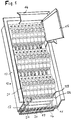
- FIG. 1 illustrates a distribution system 12 which is cut off towards the bottom and which consists of a housing 13 to be inserted into masonry, a frame 14 (shown cut off) and a front door 15 (also shown cut off).
- a distributor base 16 with laterally projecting, flange-like profile formations 17 and 18 is arranged and fastened.
- This distributor socket 16 is formed by an extruded profile made of insulating material and has a plurality of — in the present case nine — vertical receiving pockets 19.
- a busbar 20 is arranged in each of these receiving pockets 19.
- flange-like profile formations 17 and 18 (not visible in this illustration) are attached supporting members, on which, as can be seen from this illustration, three rows of installation devices 21 are now held in a latching manner.
- the contacting connection between the individual installation devices 21 and the busbars 20 takes place in each case by means of a separate, approximately angularly bent plug element 22, which can be plugged together at one end into a contact connection point 23 of the installation device 21 and at the other end with the associated busbar (20) is.
- three plug-in bridges 24 are used to supply power to the individual busbars 20 of the busbar system, all of which are of completely identical design, but which are mounted laterally offset from one another. Further features of these jumpers 24 will be explained below.
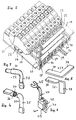
- FIG. 1 The row of installation devices 21 at the bottom in FIG. 1 is illustrated again in FIG. 2 on a somewhat enlarged scale.
- the installation devices 21 are, however, not immediately recognizable, snapped onto the support member 25 and thus held next to one another.
- This support member 25 is in turn fastened to the laterally projecting, flange-like profile formations 17 and 18 of the distributor base 16 by means of screw elements 26.
- the individual installation devices 21 are connected in contact with the busbars 20 via the plug-in elements 22 already mentioned, whereby - as already explained above - one end of the plug-in element 22 is inserted into the contact connection point 23 of the associated installation device 21 and the other end of the plug-in element 22 with the associated one Busbar 20 is plugged together.
- these busbars have an approximately U-shaped cross-sectional profile. The latter end of a plug-in element 22 is inserted between the two free legs of this profile.
- each of the busbars 20 contacts a plug element 22 in each of the rows of installation devices.
- the jumpers 24 already mentioned each have at their one longitudinal end a connection point in the form of a box-shaped screw terminal 27, in which a cable feeding the current can be fastened in a contacting manner.
- Three knife contacts 28, 29 and 30 protrude from the broad sides of the plug-in jumpers 24 facing away from the screw-type connection terminals 27 and can be adhesively inserted into correspondingly assigned busbars 20.
- the distance between the individual knife contacts 28, 29 and 30 is selected such that a first and then every third busbar (20) can be contacted.
- a total of nine power rails 20 are supplied with a mains voltage from the three jumpers 24.
- FIG. 3 Such a plug-in member 22 is illustrated in FIG. 3 in a perspective view. It can be seen that this plug-in element 22 has an angular shape with two legs 31 and 32, which have a round cross section in their longitudinal regions which are directed towards one another and are connected to one another in the corner region. The free end of the leg 31 also has a round cross-sectional contour, but the outside diameter is smaller than the previous longitudinal region of this leg 31.
- the free end of the leg 32 has a (for example hammered) flattening, which tapers a little in thickness towards the extreme end and whose thickness is dimensioned in such a way that this flattened, approximately spade-shaped free end of leg 32 can be adhesively inserted into a busbar 20, as can be seen in FIG .
- a (for example hammered) flattening which tapers a little in thickness towards the extreme end and whose thickness is dimensioned in such a way that this flattened, approximately spade-shaped free end of leg 32 can be adhesively inserted into a busbar 20, as can be seen in FIG .
- FIG. 4 shows, again in perspective, a plug-in element 33, the starting form of which is again formed by a round material and angled approximately in the longitudinal center. Accordingly, this plug-in member 33 also has two legs 34 and 35, one of which (34) is shown separated in sections to illustrate the round cross-sectional contour which is provided with the number 36. In contrast to the plug-in element 32 shown in FIG. 3, this plug-in element 33 has flats on both free leg ends, both of which serve as contacting areas. It is characteristic of this plug-in member 33 that the essential extension planes of the flattened contact areas run perpendicular to each other, in such a way that - in the assembled position of the plug-in member 33 - the contacting area to be supplied to an installation device 21 (see FIGS. 1 or 2) is parallel to the mounting plane of the installation device 21 runs, whereas the contacting area to be supplied to a busbar 20 (see again FIGS. 1 or 2) extends parallel to the side walls of the installation devices 21.
- FIG. 5 illustrates in two individual representations a plug-in member 37, the starting form of which is formed by an angular stamped part made of sheet metal or strip material with the legs 38 and 39, see the representation above in the drawing 5.
- This plug-in member 37, with legs 38 and 39 initially running completely evenly, is then deformed in one operation, one leg 39 being bent by twisting the corner region by approximately 90 °, see the lower illustration in FIG. 5 there is again a shape with two contacting areas, the essential extension planes of which are located practically the same as is the case with the plug element 33 according to FIG. 4, see the explanations above.
- FIGS. 1 and 2 illustrate installation devices with different designs in addition to installation devices in a narrow construction and with connection points that are always the same, as can be seen in FIGS. 1 and 2, installation devices with different designs can also be arranged within a distribution system, the connection points of which also often are located differently than with the installation devices mentioned in narrow construction.
- These installation devices which differ from the other installation devices in terms of their design, require a power supply, but the plug-in elements according to FIGS. 3 to 5 explained above are not suitable for this.
- FIG . 6 illustrates a solution that is suitable for such needs. This shows a plug-in element 40 in the form of a box-shaped screw terminal, from which a knife contact 41 originates.
- This knife contact 41 is integrally connected to a screw terminal part 42, the latter being surrounded by an insulating jacket 43.
- a strand 44 can be fastened in a contacting manner, which can be provided, for example, with a cable lug 45 at its free end.
- the latter is used to connect to an installation device with a connection point located differently than is the case with the installation devices 21 in a narrow construction.
- this plug-in element 40 can be plugged together in contact with a busbar 20 (see FIGS. 1 and 2), in the same way as is provided for the plug-in elements according to FIGS. 3 to 5.
- FIG. 7 shows a jumper 24, as has already been described in connection with the explanations for Figure 2. It has an essentially rail-shaped design and contains at its one longitudinal end the box-shaped screw terminal 27 already mentioned above. From the side of the rail-shaped shape facing away from the screw terminal 27, the knife contacts 28, 29 and 30 also mentioned go out, which in this The illustration is better recognizable than in FIG. 2. It should also be mentioned that the knife contacts 28, 29 and 30 mentioned are not insulated, but the rest of the longitudinal region of this jumper 24 is surrounded by insulation all around, except for the inside of the screw terminal 27. From It is of interest how the metallic body is designed without the insulating sheath mentioned, because this cannot be seen in FIG. 7; but probably the figure 8 .
- This extruded profile 46 has an essentially E-shaped shape, namely a long connecting leg 47, from which short legs 48, 49 and 50 projecting vertically. These latter legs 48 to 50 represent the knife contacts which are numbered 28 to 30 in FIG.
- a shaped area 51 with a rectangular cross section is provided with an opening 52 arranged therein.
- one or more threaded bores are made at right angles to the opening 52 on the rectangular shaped region 51, in the present case the threaded bores 53 and 54 to be able to clamp contacting inserted cable into the opening 52.
- a longitudinal region separated from the extruded profile 46, as can be seen in FIG. 8, is then to be encased or encapsulated with an insulating material, as has already been explained for the plug-in bridge 24 according to FIG. 7, that is to say the short legs 48, 49 and 50 are not encased and the end faces of the rectangular shaped area 51 must also remain free of plastic encapsulation at least in the area of the opening 52.
- the latter also applies to the threaded bores 53 and 54, which, however, can be surrounded by pipe socket-like collars, as can be seen in FIG. 7. The latter can not only serve as protection against contact, but also as a guide for a screwing tool.
- FIG. 9 illustrates a longitudinal section through a jumper 55, which is shown in perspective in the rest.
- This plug-in bridge differs from the plug-in bridge 24 shown in FIG. 7 and its metallic insert in the form of the extruded profile 46 according to FIG. 8 by a different design of the metallic insert.
- This consists namely of a metal band 56 which is angled and folded as shown, the longitudinal course of which begins at the end region 57 on the right in the illustration, which can be clearly seen from the illustration.
- a plug-in contact 58 is formed by largely folding it together, after a longer section in the plane of the end region 57, a further plug-in contact 59 is formed and finally a third plug-in contact 60.
- a contact connection region 61 is formed, which with a or two passages 62 and screw threads incorporated therein.
- a type of box terminal is formed, which is used to connect a current-carrying line.
- a connection screw 63 can be seen in this box area, which is equipped with a roof-shaped thrust washer 64 on its area located inside the box.
- This metallic structure made of the metal strip 56 is extrusion-coated with an insulating material 65, as shown, but the plug contacts 58, 59 and 60 mentioned remain free. It is needless to say that the front ends of the box-like contact connection area 61 must also be free and accessible.
- FIG. 10 shows a perspective view of a busbar 66 which, unlike the busbars in FIGS. 1 and 2, does not form a cross-sectional profile that is rigid in itself. Rather, this busbar 66 is formed from a flat sheet metal material in the initial shape, in such a way that it has an approximately heart-shaped cross-sectional profile. In this case, both lateral edge areas 67 and 68 of the originally flat initial shape end in such a way that they are directed into the interior of the profile and are apart from one another.
- Such a busbar (66) is able to spring apart to a certain extent, namely when a knife contact is inserted into the remaining longitudinal slot. In the same way, this busbar can also be compressed to a certain extent in such a way that it can be inserted into a receiving pocket of a distributor base which is narrowed on the access side.
- FIG. 11 . 1 and 2 The arrangement of a busbar, as has just been explained and shown in FIG. 10, within a receiving pocket of a distributor base is shown in FIG . 11 . 1 and 2, this represents a region of a distributor base 69 which is broken off on both sides.
- this distributor base 69 receiving pockets 70, 71, 72 and, to the left and right thereof, further receiving pockets are formed. Looking upward in the illustration, these receiving pockets 70 to 72 have slit-shaped pocket openings 73, 74 and 75 which, as can be seen, are narrowed relative to the remaining pocket cross section.
Landscapes
- Engineering & Computer Science (AREA)
- Power Engineering (AREA)
- Connector Housings Or Holding Contact Members (AREA)
- Coupling Device And Connection With Printed Circuit (AREA)
- Installation Of Bus-Bars (AREA)
- Housings And Mounting Of Transformers (AREA)
Abstract
Description
Die Erfindung bezieht sich auf eine Verteileranlage mit wenigstens zwei, vorzugsweise horizontal verlaufenden, untereinander angeordneten, jeweils auf einem Tragorgan befestigten Reihen von elektrischen Installationsgeräten in Schmalbauweise, deren Stromeinspeisung über ein isolierend abgestütztes Stromschienensystem und zugeordnete Steckorgane erfolgt.The invention relates to a distribution system with at least two, preferably horizontally running, arranged one below the other, each mounted on a support member rows of electrical installation devices in narrow construction, the power supply via an insulating supported busbar system and associated plug-in elements.
Bei der konventionellen Installationstechnik für Verteileranlagen, wie sie für Einzelhaushalte, Mehrfamilienhäuser, Bürogebäude und vergleichbare Baulichkeiten vorgesehen sind, werden die einzelnen Installationsgeräte über eine aufwendige Einzelverdrahtung stromeingangsseitig mit Spannung versorgt. Diese Verdrahtungstechnik ist sehr zeitaufwendig und kann in aller Regel nicht fabrikseitig vorgefertigt werden.With conventional installation technology for distribution systems, such as those intended for individual households, apartment buildings, office buildings and comparable structures, the individual installation devices are supplied with voltage via a complex individual wiring on the current input side. This wiring technology is very time-consuming and can usually not be prefabricated at the factory.
Zur Vereinfachung der Installationsarbeiten am Aufstellungsort und somit zur Kostenverbilligung ist man zunehmend dazu übergegangen, sogenannte Verdrahtungshilfen fabrikseitig vorzufertigen, beispielsweise solche in Gestalt von Kammschienen, Phasenschienen und dergleichen. Für den zur Rede stehenden Zweck ist beispielsweise ein Sammelschienenblock bekannt geworden, wie er dem DE-GM 87 00 153 zu entnehmen ist. Ein solcher dreipoliger Sammelschienenblock dient der Spannungsversorgung von Schaltgeräten, die also alle gleichzeitig mit den ihnen zugeordneten Stromphasen verbunden werden können. Die einzelnen Sammelschienen, die - gegeneinander isoliert - in einem mehrwandigen Kastenprofil aus Isolierstoff angeordnet und gehalten sind, weisen in regelmäßigen Abständen Anschlußlaschen auf, die von der Anschlußseite der einzelnen Installationsgeräte her unmittelbar in deren Schraubanschlußbuchsen eingefügt werden. Eine derartige Anschlußtechnik ist, insbesondere wenn es sich um Verteileranlagen mit einer größeren Anzahl von Installationsgeräten handelt, durchaus zeitsparend und zudem auch noch platzsparend. Ein Nachteil hierbei ist aber darin zu sehen, daß bei sogenannten Nachinstallationen die gesamte zugangsseitige Verdrahtung aller auf einer Tragschiene angeordneten und mit dem Sammelschienenblock verbundenen Installationsgeräte gelöst werden muß, um die zusätzlichen Installationsgeräte in das System mit einfügen zu können. Gleiches gilt für den Fall, daß einzelne Installationsgeräte ausgewechselt werden müssen, sei es deshalb, weil sie defekt sind, oder dann, wenn beispielsweise anstelle eines Installationsgerätes mit einer geringeren Nennleistung ein solches mit einer höheren Nennleistung eingesetzt werden soll.To simplify the installation work at the installation site and thus to reduce costs, there has been an increasing trend to prefabricate so-called wiring aids at the factory, for example those in the form of comb rails, phase rails and the like. For the purpose in question, for example, a busbar block has become known, as can be found in DE-GM 87 00 153. Such a three-pole busbar block serves to supply switching devices with voltage, which can therefore all be connected simultaneously to the current phases assigned to them. The individual busbars, which are arranged and held - insulated from one another - in a multi-walled box profile made of insulating material, have connection straps at regular intervals, which are inserted directly into the screw connection sockets from the connection side of the individual installation devices. Such a connection technology is, especially when it comes to distribution systems with a larger number of installation devices, quite time-saving and also space-saving. A disadvantage here, however, can be seen in the fact that in the case of so-called post-installations, the entire access-side wiring of all installation devices arranged on a mounting rail and connected to the busbar block must be released in order to be able to insert the additional installation devices into the system. The same applies in the event that individual installation devices have to be replaced, be it because they are defective, or if, for example, instead of an installation device with a lower nominal output, one with a higher nominal output is to be used.
Eine Niederspannungsverteilung, bei welcher der eben genannte Nachteil vermieden wird, ist der EP 0 229 590 A1 zu entnehmen. Bei dieser bekannten Kontstruktion ist es vorgesehen, die aufzunehmenden Installationsgeräte nahe ihrer Unterseite bzw. ihrer Befestigungsebene mit schwalbenschwanzförmigen Aussparungen zu versehen, in welche jeweils sowohl eine sogenannte Stecktulpe, d. h. ein klemmbackenartiges Kontaktorgan, als auch ein Arretierschieber einfügbar sind. Sowohl diese Aussparung als auch der Arretierschieber sind mit quer zum Verlauf der Aussparung versehenen Ausnehmungen versehen, in welche seitliche Führungsplättchen der Stecktulpe einzugreifen vermögen. In einem gesonderten Arbeitsgang, der vorzugsweise am Aufstellungsort der Niederspannungsverteilung vorzunehmen ist, können diese Stecktulpen in unterschiedlichen Positionen am Installationsgerät befestigt und mittels des Arretierschiebers fixiert werden. Die Stecktulpen selbst sind mit flexiblen Leitungen verbunden, welche in eine Anschlußkontaktstelle des jeweiligen Installationsgerätes einfügbar und hierin kontaktierend befestigbar sind. Diese Stecktulpen kontaktieren nun mit einem Schienensystem, das in einem Stecksockel gehalten ist. Diese Konstruktion ist, was die Halterung und kontaktierende Verbindung der Stecktulpen betrifft, aufwendig, und zwar sowohl bezüglich der erforderlichen Teile als auch der Notwendigkeit, diese Stecktulpen jeweils in die erwünschte Position bringen zu müssen, was - wie oben bereits ausgeführt - in aller Regel erst am Aufstellungsort geschehen kann oder wird. Zu nennen ist aber noch ein anderer Nachteil dieser bekannten Konstruktion, der insbesondere dann augenfällig wird, wenn innerhalb einer Verteileranlage zwei oder gar deutlich mehr als zwei Reihen von Installationsgeräten anzuordnen sind. In diesem Falle benötigt jede der einzelnen Reihen von Installationsgeräten einen gesonderten Stecksockel und jeder Stecksockel benötigt eine eigene Stromeinspeisung für die im Stecksockel gehaltenen Stromschienen. Diese zuletzt genannten Nachteile gelten übrigens auch bei der Verwendung von Sammelschienenblöcken entsprechend dem oben bereits genannten DE-GM 87 00 153.A low-voltage distribution in which the disadvantage just mentioned is avoided can be found in EP 0 229 590 A1. In this known construction, it is provided to provide the installation devices to be accommodated near their underside or their attachment level with dovetail-shaped recesses, into each of which a so-called plug tulip, ie a jaw-like contact member, and a locking slide can be inserted. Both this recess and the locking slide are provided with recesses which are provided transversely to the course of the recess and in which lateral guide plates of the plug-in tulip can engage. In a separate operation, which should preferably be carried out at the installation site of the low-voltage distribution, these plug-in tulips can be attached to the installation device in different positions and fixed by means of the locking slide. The plug-in tulips themselves are connected to flexible lines which can be inserted into a connection contact point of the respective installation device and fastened in a contacting manner therein. These plug-in tulips now contact with a rail system that is held in a plug-in base. This construction is complex in terms of the mounting and contacting connection of the plug-in tulips, both in terms of the required parts and the need to bring these plug-in tulips into the desired position, which - as already stated above - usually only can or will happen at the installation site. However, another disadvantage of this known construction is to be mentioned, which is particularly noticeable when two or even significantly more than two rows of installation devices are to be arranged within a distribution system. In this case, each of the individual rows of installation devices requires a separate plug-in base and each plug base requires its own power supply for the busbars held in the plug base. These last-mentioned disadvantages also apply when using busbar blocks in accordance with DE-GM 87 00 153 already mentioned above.
Ausgehend von dem genannten Stand der Technik stellt sich die vorliegende Erfindung zur Aufgabe, eine Verteileranlage für zwei oder mehrere Reihen von aufzunehmenden Installationsgeräten mit einer Stromeinspeisung über Stromschienen zu schaffen, welche die geschilderten Nachteile vermeidet und hinsichtlich des erforderlichen Teile- und Montageaufwandes möglichst preisgünstig und auch platzsparend herstellbar ist. Konkret ausgedrückt, soll die zu schaffende Verteileranlage so ausgebildet sein, daß eine Ergänzung der vorhandenen Installationsgeräte oder ein Auswechseln vorhandener Installationsgeräte auf einfache Weise möglich ist, ohne einen Stromschienenblock vorübergehend entfernen oder mindestens die Schraubverbindungen benachbarter Installationsgeräte lösen zu müssen, es soll weiterhin vermieden werden, am Aufstellungsort noch Handhabungen an den einzelnen Installationsgeräten vornehmen zu müssen, wenn man von der Herstellung einer Klemmverbindung absieht, und schließlich soll vermieden werden, jede einzelne Reihe von Installationsgeräten mit gesonderten Stromeinspeisungen ausstatten zu müssen.Starting from the prior art mentioned, the present invention has for its object to provide a distribution system for two or more rows of installation devices to be accommodated with a power supply via busbars, which avoids the disadvantages described and in terms of the required parts and assembly effort as inexpensively and as possible can be produced in a space-saving manner. In concrete terms, the distribution system to be created should be designed in such a way that it is easy to supplement the existing installation devices or to replace existing installation devices without temporarily removing a busbar block or at least having to loosen the screw connections of adjacent installation devices. to have to carry out manipulations on the individual installation devices at the installation site, if one does not make a clamp connection, and finally to avoid having to equip each individual row of installation devices with separate power supplies.
Dieses vielschichtige und in gewisser Weise anspruchsvolle Ziel wird erfindungsgemäß dadurch erreicht, daß für die Halterung des Stromschienensystems ein zwei oder mehreren Reihen von Installationsgeräten gemeinsam dienender Verteilersockel vorgesehen wird, welcher mit vertikal bzw. quer zu den Installationsgeräte-Reihen verlaufenden Aufnahmetaschen und darin angeordneten Stromschienen ausgestattet ist, weiterhin dadurch, daß die Anzahl der Aufnahmetaschen in diesem Verteilersockel der höchstmöglichen Anzahl von in einer Reihe anordendbaren Installationsgeräten gleicht, und schließlich ist noch vorgesehen, daß die kontaktierende Verbindung zwischen den einzelnen Installationsgeräten und den zugeordneten Stromschienen jeweils mittels eines gesonderten Steckorgans erfolgt, welches mit seinem einen Längsende in eine Kontaktanschlußstelle eines Installationsgerätes einfügbar und mit seinem anderen Ende mit der besagten Stromschiene kontaktierend zusammensteckbar gestaltet ist. Eine derartige Konstruktion ist insbesondere in jenen Fällen sehr zweckmäßig, in denen nicht nur zwei, sondern mehrere oder sogar recht viele Reihen von Installationsgeräten innerhalb einer Verteileranlage untereinander anzuordnen und mit Stromeinspeisungen zu versehen sind. Es bedarf nämlich in diesem Falle - jedenfalls bei Verteileranlagen mit "normaler", d. h. nicht übermäßig großer Breite - nur eines einzigen Verteilersockels, dessen einzelne Stromschienen auch nur an einer Stelle mit einer Phaseneinspeisung verbunden werden müssen, völlig unabhängig davon, wie groß die Anzahl der untereinander gelegenen Reihen von Installationsgeräten ist. Außerdem ist es ohne größere Schwierigkeiten möglich, jedes einzelne der Installationsgeräte aus jeder Reihe herauszulösen und gegen ein anderes Gerät zu ersetzen bzw. auszutauschen. Zwar geht diese Lösung in einem gewissen Ausmaß zu Lasten der gesamten Bauhöhe, was jedoch durch die erzielbaren Montageerleichterungen am Aufstellungsort und, wie eben bereits gesagt, durch die einfache Auswechselbarkeit einzelner Installationsgeräte, durchaus in Kauf genommen werden kann. Eine derartige Verteileranlage kann weitgehend fabrikmäßig vorgefertigt werden, einschließlich der Verbindung der einzelnen Stromschienen mit Anschlüssen für die Stromeinspeisung.This multi-layered and somewhat demanding goal is achieved according to the invention in that for the mounting of the busbar system a two or more rows of installation devices serving jointly distributor base is provided, which with vertical or transverse to the rows of installation devices receiving pockets and busbars arranged therein is furthermore characterized in that the number of receiving pockets in this distributor base is equal to the maximum possible number of installation devices which can be arranged in a row, and finally it is also provided that the contacting connection between the individual installation devices and the associated busbars takes place in each case by means of a separate plug element, which can be inserted with its one longitudinal end into a contact connection point of an installation device and can be plugged together with its other end in contacting manner with the said busbar. Such a construction is particularly useful in those cases in which not only two, but several or even quite a number of rows of installation devices are to be arranged with one another within a distribution system and to be supplied with power supplies. This is because in this case - at least in the case of distribution systems with a "normal", ie not excessively large width - only a single distribution base is required, the individual busbars of which must be connected to a phase feed at only one point, regardless of how large the number of rows of installation devices one below the other. In addition, it is possible without major difficulties to remove each of the installation devices from each row and to replace or replace them with another device. To a certain extent, this solution is at the expense of the overall height, which, however, can be tolerated by making installation easier at the installation site and, as already mentioned, by simply replacing individual installation devices. Such a distribution system can be largely prefabricated in the factory, including the connection of the individual busbars with connections for the power supply.
Eine vorteilhafte Weiterbildung des Erfindungsgedankens ist in dem Vorschlag zu sehen, den Verteilersockel von einem entsprechend dem jeweiligen Bedarf abgelängten Endlosprofil aus Isolierstoff zu bilden, dessen Längsenden im übrigen mit einer Abdeckung oder mit einer Kappe versehen werden können, wenn der gebotene Berührungsschutz dieses wünschenswert macht. Ein entsprechend gestaltetes Endlosprofil ist, abgesehen einmal von den Werkzeugkosten, preiswert und hinreichend maßhaltig herzustellen und bedarf, außer dem Ablängen und eventuell der Anbringung von Befestigungsbohrungen oder dergleichen, keiner weiteren Nacharbeit.An advantageous development of the concept of the invention can be seen in the proposal to form the distributor base from a continuous profile of insulating material cut to length according to the respective requirements, the longitudinal ends of which can be provided with a cover or a cap if the protection against contact makes this desirable. A suitably designed endless profile is, apart from the tool costs, inexpensive and sufficiently dimensionally producible and, apart from cutting to length and possibly attaching fastening holes or the like, requires no further rework.
Eine vorteilhafte Weiterbildung des zuletzt genannten Ausgestaltungsgedankens ist darin zu sehen, das Endlosprofil für die Bildung des Verteilersockels mit seitlich vorstehenden flanschartigen Profilausformungen zu gestalten, die sowohl der Befestigung des Verteilersockels innerhalb der Verteileranlage, als auch zugleich der Befestigung von Tragorganen für die Halterung der einzelnen Reihen der Installationsgeräte dienen können. Der Mehraufwand für solche flanschartigen Profilausführungen ist vernachlässigbar gering, es können hiermit aber zusätzliche Teile, die sonst eventuell erforderlich wären, von vornherein eingespart werden.An advantageous development of the last-mentioned design idea is to be seen in designing the endless profile for the formation of the distributor base with laterally projecting flange-like profile formations, both the fastening of the distributor base within the distribution system and also the fastening of support members for holding the individual rows the installation devices can serve. The additional effort for such flange-like profile designs is negligible, but it can save additional parts that might otherwise be necessary from the outset.
Eine zweckmäßige Ausgestaltung des Erfindungsgedankens kann darin gesehen werden, die im Verteilersockel vorgesehenen Aufnahmetaschen für die Aufnahme der Stromschienen auf ihrer den zu kontaktierenden Installationsgeräten zugewandten Seite mit einer dem Durchtritt der Steckorgane dienenden schlitzförmigen Taschenöffnung zu versehen, die gegenüber dem übrigen Taschenquerschnitt verengt ist. Auf diese Weise können in die Aufnahmetaschen eingefügte Stromschienen in ihrer Lage fixiert und zugleich gegen ein Heraustreten gesichert werden. Außerdem wird durch eine verengte Taschenöffnung der stets erwünschte Berührungsschutz verbessert.An expedient embodiment of the concept of the invention can be seen in providing the receiving pockets provided in the distributor base for receiving the busbars on their side facing the installation devices to be contacted with a slot-shaped pocket opening serving for the passage of the plug-in elements and which is narrower than the remaining pocket cross section. In this way, busbars inserted into the receiving pockets can be fixed in their position and at the same time secured against escaping. In addition, the always desired touch protection is improved by a narrowed pocket opening.
Eine andere vorteilhafte Ausgestaltung der vom Erfindungsgegenstand umfaßten Teile ist in dem Vorschlag zu sehen, die Stromschienen mit einer U-förmigen oder C-förmigen Querschnittskontur auszubilden. Hierbei können die freien Enden der U-förmigen oder C-förmigen Querschnittskontur einen Abstand voneinander aufweisen, der mindestens geringfügig kleiner ist als die Breite bzw. Dicke eines Steckorgans, welches zwischen diese freien Enden bzw. Schenkel der so gestalteten Stromschiene einfügbar sind. Hierdurch ist eine Klemmwirkung erzielbar, die durchaus sehr erwünscht ist, vorteilhaft kommt aber hinzu, daß die Ausbildung der einzelnen Steckorgane einfacher gestaltet werden kann, d. h. keiner gabelförmigen, zueinander federnder Klemmbacken oder dergleichen bedürfen.Another advantageous embodiment of the parts included in the subject matter of the invention can be seen in the proposal to design the busbars with a U-shaped or C-shaped cross-sectional contour. In this case, the free ends of the U-shaped or C-shaped cross-sectional contour can be at a distance from one another which is at least slightly smaller than the width or thickness of a plug element which can be inserted between these free ends or legs of the busbar designed in this way. In this way, a clamping effect can be achieved, which is very desirable, but it is also advantageous that the design of the individual plug-in elements can be made simpler. H. no fork-shaped, resilient clamping jaws or the like are required.
Eine spezielle, bezüglich der Montage und eventuell auch einer Materialeinsparung vorteilhafte Gestaltung der Stromschienen ist in dem Vorschlag zu sehen, diese aus einem in der Ausgangsform ebenen Blechmaterial herzustellen und dieses Ausgangsmaterial in ein herzformartiges Querschnittsprofil zu formen, wobei beide seitlichen Randungsbereiche der Ausgangsform in das Profilinnere gerichtet enden und voneinander einen Abstand aufweisen. Derartige Stromschienen lassen sich bei der Montage mit dem zugeordneten Verteilersockel in einem hinreichenden Ausmaß seitlich zusammendrücken, so daß sie durch eine schlitzförmige Taschenöffnung mit einem nach außen hin verengten Taschenquerschnitt hindurch in die Taschen eines Verteilersockels einfügbar sind. Bei einer entsprechenden Bemessung der Stromschienen kann erreicht werden, daß sie im Inneren der besagten Taschen an deren seitlichen Wandungen selbsthaftend anliegen. Ein weiterer Vorteil derart ausgebildeter Stromschienen ist darin zu sehen, daß sie eine vergleichsweise große Oberfläche aufweisen, wodurch ein günstigerer Wärmeabfuhreffekt erzielt werden kann.A special design of the busbars that is advantageous in terms of assembly and possibly also material savings can be seen in the proposal to produce them from a sheet metal material that is flat in the initial shape and to shape this starting material into a heart-shaped cross-sectional profile, with both lateral edge areas of the initial shape into the interior of the profile end directed and have a distance from each other. Such busbars can be laterally compressed to a sufficient extent during assembly with the associated distributor base, so that they can be inserted into the pockets of a distributor base through a slot-shaped pocket opening with a pocket cross-section narrowed towards the outside. With a corresponding dimensioning of the busbars it can be achieved that they abut self-adherently on the side walls of said pockets inside. Another advantage of busbars designed in this way is that they have a comparatively large surface area, as a result of which a more favorable heat dissipation effect can be achieved.
Ein anderer vorteilhafter Ausgestaltungsvorschlag bezieht sich auf die Ausbildung der Steckorgane zur kontaktierenden Verbindung zwischen einem Installationsgerät und einer zugeordneten Stromschiene. Diese Steckorgane können eine weitgehend starre, etwa im Bereich ihrer Längsmitte abgewinkelte Formgebung aufweisen, wobei es vorgesehen ist, sie mit ihrem einen freien Ende in die Kontaktanschlußstelle des zugeordneten Installationsgerätes einzufügen und mit ihrem anderen freien Ende mit der entsprechenden Stromschiene zusammenzustecken. Solche Steckorgane können nach der Montage der einzelnen Installationsgeräte diesen und den zugeordneten Stromschienen angefügt und bei Bedarf von diesen wieder entfernt werden, ohne benachbarte Geräte bzw. deren Steckorgane in irgendeiner Weise zu beeinträchtigen.Another advantageous embodiment proposal relates to the design of the plug-in elements for the contacting connection between an installation device and an associated busbar. These plug-in elements can have a largely rigid, approximately angled shape in the region of their longitudinal center, it being provided that they be inserted with one free end into the contact connection point of the associated installation device and with their other free end connected to the corresponding busbar. After the installation of the individual installation devices, such plug-in elements can be attached to these and the associated busbars and, if necessary, removed from them again without impairing neighboring devices or their plug-in elements in any way.
Einem konkreten Gestaltungsvorschlag zufolge können diese Steckorgane aus einem im Querschnitt runden oder quadratischen Ausgangsmaterial hergestellt werden, wobei die freien Enden zu abgeflachten oder verjüngten Kontaktierungsbereichen verformt sind. Einem alternativen Gestaltungsvorschlag zufolge können die Steckorgane als in ihrer Ausgangsform winkelförmige Stanzteile aus einem Blech- oder Bandmaterial hergestellt werden, deren einer Schenkel anschließend - unter Verdrillung des Eckbereiches - um ca. 90° abgebogen werden. Bei derartigen Steckorganen erübrigt es sich, die Kontaktierungsbereiche abzuflachen. Für beide Gestaltungsformen von Steckorganen kann es vorteilhafterweise vorgesehen werden, die wesentlichen Erstreckungsebenen ihrer abgeflachten bzw. ebenen Kontaktierungsbereiche senkrecht zueinander verlaufen zu lassen, und zwar derart, daß - in montierter Lage - der dem Installationsgerät zugeführte Kontaktierungsbereich parallel zur Befestigungsebene des Installationsgerätes verläuft, hingegen der einer Stromschiene zugeführte Kontaktierungsbereich sich parallel zu den seitlichen Wandungen des Installationsgerätes erstreckt. Eine derartige Anordnung der abgeflachten bzw. ebenen Kontaktierungsbereiche der einzelnen Steckorgane begünstigt deren Montage und gegebenenfalls deren Demontage im Falle der Notwendigkeit, ein Installationsgerät auszuwechseln.According to a concrete design proposal, these plug-in elements can be produced from a starting material that is round or square in cross-section, the free ends being deformed into flattened or tapered contacting areas. According to an alternative design proposal, the plug-in elements can be produced as an angular stamped parts from sheet metal or strip material, one leg of which is then bent by approximately 90 ° while twisting the corner area. With such plug-in elements, it is not necessary to flatten the contacting areas. For both designs of plug-in elements, it can advantageously be provided that the essential extension planes of their flattened or planar contacting areas run perpendicular to one another, in such a way that - in the assembled position - the contacting area supplied to the installation device runs parallel to the mounting plane of the installation device, whereas the a track supplied contacting area extends parallel to the side walls of the installation device. Such an arrangement of the flattened or flat contacting areas of the individual plug-in elements favors their assembly and, if necessary, their disassembly in the event of the need to replace an installation device.
In Verteileranlagen der zur Rede stehenden Art müssen häufig außer den nebeneinander aufgereihten Installationsgeräten in Schmalbauweise auch solche Installationsgeräte aufgenommen werden, deren Gestalt und Anschlußmöglichkeit abweicht von den übrigen Installationsgeräten. Hierbei kann es sich beispielsweise um Klingeltransformatoren, Zeitglieder für eine Treppenhausbeleuchtung, um Funktionsorgane für eine Alarmanlage oder dergleichen Funktionselemente handeln. Für die kontaktierende Verbindung solcher Installationsgeräte mit den Stromschienen werden - gemäß einem zweckmäßigen Weiterbildungsvorschlag - Steckorgane in Form von kastenförmigen Schraubanschlußklemmen empfohlen, von denen jeweils ein Messerkontakt zur Kontaktierung einer Stromschiene ausgeht. In die Schraubanschlußklemme eines solchen Steckorgans kann nun das eine Ende eines leicht verformbaren Anschlußdrahtes oder einer flexiblen Anschlußlitze eingefügt und hierin kontaktierend befestigt werden. Das andere Ende dieses Drahtes bzw. dieser Litze ist der Kontaktanschlußstelle eines beliebig gestalteten Installationsgerätes zuzuführen, d. h. auch für solche, gestaltungsmäßig von einer Norm abweichenden Installationsgeräte ist eine einfache Kontaktierungsmöglichkeit mit den besagten Stromschienen geboten.In distribution systems of the type in question, in addition to the installation devices lined up next to one another, installation devices whose shape and connection option differs from the other installation devices must also be accommodated. This can be, for example, bell transformers, timers for staircase lighting, functional elements for an alarm system or similar functional elements. For the contacting connection of such installation devices with the busbars, plug-in elements in the form of box-shaped screw connection terminals are recommended, in accordance with an expedient further training suggestion, each of which is provided with a knife contact for contacting a busbar. One end of an easily deformable connecting wire or a flexible connecting wire can now be inserted into the screw terminal of such a plug element and fastened in contacting manner therein. The other end of this wire or this strand is to be fed to the contact connection point of an installation device of any design, ie a simple possibility of contacting said busbars is also provided for installation devices deviating from a standard in terms of design.
Die einzelnen Stromschienen einer Verteileranlage bedürfen einer Stromeinspeisung, d. h. einer kontaktierenden Verbindung mit einer Phase des der Verteileranlage zugeführten Stromnetzes. Diese Stromeinspeisung kann beispielsweise über Installationsgeräte in Form von Leitungsschutzschaltern erfolgen. Für die oben vorgeschlagene Konzeption würde dieses bedeuten, daß eine komplette Reihe von Leitungsschutzschaltern aufgewendet werden muß, um alle einzelnen Stromschienen mit Spannung zu versorgen. Dieses ist, was den Gerätebedarf betrifft, recht aufwendig, insbesondere dann, wenn die Anzahl der in einer Verteileranlage vorhandenen Reihen von Installationsgeräten nicht sehr groß ist. Eine zweckmäßige Weiterbildung des Erfindungsgedankens ist nun darin zu sehen, zur Stromversorgung des Stromschienensystems Steckbrücken vorzusehen, die jeweils aus einer vorzugsweise in Gestalt einer kastenförmigen Schraubanschlußklemme gebildeten Anschlußstelle bestehen, welch letztere mit einem sich seitlich erstreckenden, schienenartigen Brückenglied einstückig oder kontaktierend fest verbunden ist, von dem wenigstens zwei Messerkontakte zur Kontaktierung einer entsprechenden Anzahl von Stromschienen ausgehen. Einer konkreten Ausbildungsform zufolge gehen von diesem Brückenglied wenigstens drei Messerkontakte aus, die so voneinander beabstandet und positioniert sind, daß sie jeweils jede dritte Stromschiene des Stromschienensystems zu kontaktieren vermögen. Auf diese Weise ist es möglich, mit insgesamt drei Steckbrücken wenigstens neun Stromschienen mit einer Stromeinspeisung auszustatten. Derartige Steckbrücken sind, was den Geräteaufwand betrifft, durchaus preisgünstiger als die Verwendung von Leitungsschutzschaltern zur Einspeisung, außerdem ist der erforderliche Platzaufwand innerhalb der Verteileranlage geringer.The individual busbars of a distribution system require a current feed, ie a contacting connection with a phase of the power network supplied to the distribution system. This current can be fed in, for example, via installation devices in the form of circuit breakers. For the concept proposed above, this would mean that a complete series of circuit breakers would have to be used to supply all the individual busbars with voltage. This is quite complex in terms of device requirements, especially when the number of rows of installation devices in a distribution system is not very large. An expedient further development of the inventive concept is to be seen in providing jumpers for the power supply of the busbar system, each of which consists of a connection point preferably formed in the form of a box-shaped screw connection terminal, the latter being connected in one piece or in a contacting manner to a laterally extending, rail-like bridge member which run out of at least two knife contacts for contacting a corresponding number of busbars. According to a specific form of training, at least three knife contacts extend from this bridge member, which are spaced apart and positioned such that they are able to contact every third busbar of the busbar system. In this way, it is possible to equip at least nine busbars with a power supply with a total of three jumpers. Such jumpers are, in terms of equipment costs, cheaper than the use of circuit breakers for the feed, and the space required within the distribution system is also less.
Eine zweckmäßige Ausgestaltung der eben genannten Steckbrücken ist in dem Vorschlag zu sehen, diese - ausgenommen die vorgesehenen Kontaktierungsbereiche der Anschlußstelle und der Messerkontakte - ringsum mit Isolierstoff zu ummanteln. Auf diese Weise ist ein in jedem Falle erwünschter Berührungsschutz gegeben, der auch dann vorteilhaft ist, wenn diese Steckbrücken durch eine entsprechende Isolierstoffplatte oder dergleichen innerhalb der Verteileranlage abgedeckt sind.An expedient embodiment of the plug-in bridges just mentioned can be seen in the proposal to encase them all around with insulating material, with the exception of the intended contacting areas of the connection point and the knife contacts. In this way, protection against accidental contact is provided in any case, which is also advantageous if these jumpers are covered by a corresponding insulating material plate or the like within the distribution system.
Die stromleitenden Teile einer solchen Steckbrücke können beispielsweise einstückig von einem entsprechend geformten Strangpreßteil abgelängt sein. Einem vorteilhaften Ausgestaltungsvorschlag zufolge kann es aber auch vorgesehen sein, sowohl die Anschlußstelle, als auch das Brückenglied, als auch schließlich die von diesem Brükkenglied ausgehenden Messerkontakte aus einem einzigen Metallband, beispielsweise aus einem Kupfer- oder einem Aluminiumband, herzustellen, welch letzteres entsprechend abgewinkelt und gefaltet und sodann mit einem Isolierstoffmantel umspritzt ist. Derartig gestaltete Steckbrücken können, jedenfalls dann, wenn der Bedarf an Steckbrücken nicht übermäßig groß ist, in der Herstellung letztendlich preisgünstiger sein als die Verwendung von einem entsprechenden Strangpreßprofil. Letzteres deshalb, weil die Breite der einzelnen Steckbrücken nur relativ gering sein muß, und aus einem beispielsweise zwei Meter langen Strangpreßprofil bereits einhundert oder noch mehr an Steckbrücken-Teilen - durch Ablängen - hergestellt werden können.The current-conducting parts of such a jumper can, for example, be cut to length in one piece from an appropriately shaped extrusion. According to an advantageous design proposal, it can also be provided to produce both the connection point and the bridge member, and finally the knife contacts emanating from this bridge member, from a single metal strip, for example from a copper or an aluminum strip, the latter of which is angled and accordingly folded and then overmolded with an insulating jacket. Such jumpers designed, at least when the need for jumpers is not excessive, can ultimately be cheaper to manufacture than the use of a corresponding extruded profile. The latter is because the width of the individual jumpers only has to be relatively small, and one hundred or even more of jumper parts can be made from a two-meter-long extruded profile - by cutting to length.
Eine vorteilhafte Weiterbildung des zuletzt genannten Gedankens, für die Herstellung eines Brückengliedes ein Metallband zu verwenden, wird vorgeschlagen, die beiden Bandbereiche der durch Zusammenfalten des Metallbandes gebildeten einzelnen Messerkontakte nicht unmittelbar aneinanderliegen zu lassen, sondern vielmehr in einem Abstand voneinander zu belassen. Dieser Abstand kann sich in der Größenordnung von einem Vierteil bis zum Dreifachen der Banddicke erstrecken und sich dementsprechend um diesen Betrag, ohne sich zu verformen, federnd zueinander biegen lassen. Auf diese Weise ist die Bildung eines federnden Messerkontaktes möglich, ohne hierfür den Aufwand erwähnenswert zu vergrößern.An advantageous development of the last-mentioned idea of using a metal band for the production of a bridge member is proposed, the two band areas of the individual knife contacts formed by folding the metal band not directly letting each other rest, but rather keeping them at a distance from each other. This distance can be of the order of four to three times the strip thickness and can accordingly be resiliently bent by this amount without deforming. In this way, the formation of a resilient knife contact is possible without increasing the effort worth mentioning.
Verteileranlagen der zur Rede stehenden Art können durchaus unterschiedliche Breiten aufweisen. In diesem Zusammenhang wird vorgeschlagen, zur Vergrößerung der Anzahl von in einer Reihe anordenbaren Installationsgeräten zwei oder mehrere Verteilersockel nebeneinanderliegend innerhalb einer Verteileranlage anzuordnen. Auf diese Weise ist die Anzahl der in einer Reihe anordenbaren Installationsgeräte verdoppelbar oder sogar noch weiter vergrößerbar. Hierdurch kann auch vermieden werden, für unterschiedlich breite Verteileranlagen unterschiedliche Verteilersockel herstellen und auf Lager halten zu müssen und dennoch dieses vorgeschlagene System für unterschiedlich breite Verteileranlagen verwenden zu können.Distribution systems of the type in question can certainly have different widths. In this context, it is proposed to arrange two or more distributor bases lying side by side within a distribution system in order to increase the number of installation devices that can be arranged in a row. In this way, the number of installation devices that can be arranged in a row can be doubled or even further increased. In this way it can also be avoided to have to produce and keep in stock different manifold bases for differently wide distribution systems and still be able to use this proposed system for differently wide distribution systems.
Anhand von in den Zeichnungen dargestellten Ausführungsbeispielen und den nachfolgenden Erläuterungen hierzu sollen der Erfindungsgedanke und seine vorteihaften Ausbildungsmöglichkeiten noch einmal erklärt und verdeutlich werden.On the basis of exemplary embodiments shown in the drawings and the explanations below, the idea of the invention and its advantageous training possibilities are to be explained and clarified again.
Es zeigen:
- Figur 1
- in perspektivischer Sicht eine nach unten hin abgebrochene Verteileranlage mit mehreren darin angeordneten Reihen von Installationsgeräten,
- Figur 2
- in perspektivischer Darstellung einen nach oben hin abgeschnittenen Verteilersockel einer Verteileranlage mit einer auf diesem Verteilersockel angeordneten Reihe von Installationsgeräten und mit Steckbrücken zur Stromversorgung von Stromschienen,
- Figur 3
- eine erste Ausführungsmöglichkeit für ein Steckorgan,
- Figur 4
- eine weitere Möglichkeit für die Ausbildung eines Steckorgans,
- Figur 5
- eine dritte Gestaltungsmöglichkeit für ein Steckorgan, und zwar dessen Ursprungsform und - darunterliegend - dessen Gebrauchsform,
- Figur 6
- ein weiteres Steckorgan, und zwar für die Kontaktierung von Installationsgeräten mit einer bezüglich der Kontaktierung anders als die dargestellten Installationsgeräte ausgebildeten Geräten oder Funktionsorganen,
- Figur 7
- eine perspektivisch dargestellte Steckbrücke für die Stromeinspeisung der Stromschienen,
- Figur 8
- das abgelängte Stück eines Stranpreßprofiles, wie es für eine Steckbrücke gemäß Figur 7 Verwendung finden kann,
- Figur 9
- in einer Perspektive eine längs aufgeschnittene Steckbrücke, deren metallische Kontaktbereiche aus einem Metallband hergestellt sind,
- Figur 10
- in perspektivischer Sicht eine - in der Mitte ausgebrochene - Stromschiene und
- Figur 11
- im Schnitt einen nach beiden Seiten hin abgebrochenen Bereich eines Verteilersockels mit einer darin angeordneten Stromschiene gemäß Figur 10.
- Figure 1
- a perspective view of a distribution system broken off at the bottom with several rows of installation devices arranged therein,
- Figure 2
- a perspective view of an upwardly cut distributor base of a distribution system with a row of installation devices arranged on this distributor base and with jumpers for the power supply of busbars,
- Figure 3
- a first embodiment for a plug-in element,
- Figure 4
- another possibility for the formation of a plug-in organ,
- Figure 5
- a third design option for a plug-in element, namely its original form and - underneath - its form of use,
- Figure 6
- a further plug-in element, specifically for the contacting of installation devices with devices or functional elements designed differently in terms of contacting than the installation devices shown,
- Figure 7
- a jumper shown in perspective for the current feed of the busbars,
- Figure 8
- the cut piece of an extruded profile, as it can be used for a jumper according to Figure 7,
- Figure 9
- in one perspective a longitudinally cut jumper, the metallic contact areas of which are made from a metal band,
- Figure 10
- a perspective view of a busbar - broken out in the middle - and
- Figure 11
- on average, an area of a distributor base broken off on both sides with a busbar arranged therein according to FIG. 10.
In perspektivischer Darstellung veranschaulicht die Figur 1 eine nach unten hin abgeschnittene Verteileranlage 12, die aus einem in ein Mauerwerk einzulassenden Gehäuse 13, einem (abgeschnitten gezeigten) Blendrahmen 14 und aus einer (ebenfalls abgeschnitten gezeigten) frontseitigen Tür 15 besteht. Im Inneren dieser Verteileranlage 12 ist ein Verteilersockel 16 mit seitlich vorstehenden, flanschartigen Profilausformungen 17 und 18 angeordnet und befestigt. Dieser Verteilersokkel 16 wird von einem Strangpreßprofil aus Isolierstoff gebildet und weist mehrere - im vorliegenden Falle neun - vertikal verlaufende Aufnahmetaschen 19 auf. In diesen Aufnahmetaschen 19 sind jeweils eine Stromschiene 20 angeordnet. Oberhalb der besagten flanschartigen Profilausformungen 17 und 18 sind (in dieser Darstellung nicht erkennbare) Tragorgane befestigt, auf denen nun, wie aus dieser Darstellung zu entnehmen ist, drei Reihen von Installationsgeräten 21 in Schmalbauweise rastend gehalten sind. Die kontaktierende Verbindung zwischen den einzelnen Installationsgeräten 21 und den Stromschienen 20 erfolgt jeweils mittels eines gesonderten, etwa winkelig abgebogenen Steckorgans 22, welches mit seinem einen Ende in eine Kontaktanschlußstelle 23 des Installationsgerätes 21 und mit seinem anderen Ende mit der zugeordneten Stromschiene (20) kontaktierend zusammensteckbar ist.In a perspective view, FIG. 1 illustrates a
Zur Stromversorgung der einzelnen Stromschienen 20 des Stromschienensystem dienen im vorliegenden Falle drei Steckbrücken 24, die zwar alle völlig gleich ausgebildet sind, die jedoch seitlich zueinander versetzt montiert sind. Weitere Merkmale dieser Steckbrücken 24 sollen nachfolgend noch erläutert werden.In the present case, three plug-in
Die in der Figur 1 zuunterst gelegene Reihe der Installationsgeräte 21 ist - in etwas vergrößertem Maßstab - noch einmal in der Figur 2 veranschaulicht. Erkennbar in dieser Darstellung sind außer den Installationsgeräten 21 ein Tragorgan 25 in Gestalt einer sogenannten Hutprofilschiene sowie der Verteilersockel 16, die Steckbrücken 24 und die Stromschienen 20, von denen eine aus Anschauungsgründen herausgezogen gezeigt ist. Die Installationsgeräte 21 sind, was allerdings nicht unmittelbar erkennbar ist, auf dem Tragorgan 25 aufgerastet und somit nebeneinander gehalten. Dieses Tragorgan 25 wiederum ist auf den seitlich vorstehenden, flanschartigen Profilausformungen 17 und 18 des Verteilersokkels 16 - mittels Schraubelementen 26 - befestigt. Über die bereits erwähnten Steckorgane 22 sind die einzelnen Installationsgeräte 21 mit den Stromschienen 20 kontaktierend verbunden, wobei - wie bereits oben ausgeführt - jeweils ein Ende des Steckorgans 22 in die Kontaktanschlußstelle 23 des zugeordneten Installationsgerätes 21 eingefügt und das andere Ende des Steckorgans 22 mit der zugeordneten Stromschiene 20 zusammengesteckt ist. Wie insbesondere bei der herausgezogen gezeigten Stromschiene 20 erkennbar ist, haben diese Stromschienen ein etwa U-förmiges Querschnittsprofil. Zwischen die beiden freien Schenkel dieses Profils fügt sich das letztgenannte Ende eines Steckorgans 22 ein. Bezogen auf eine Verteileranlage 12 gemäß Figur 1, kontaktiert eine jede der Stromschienen 20 in jeder der Reihen von Installationsgeräten ein Steckorgan 22.The row of
Die bereits erwähnten Steckbrücken 24 weisen an ihrem einen Längsende jeweils eine Anschlußstelle in Gestalt einer kastenförmigen Schraubanschlußklemme 27 auf, in welcher ein den Strom einspeisendes Kabel kontaktierend befestigbar ist. Von den den Schraubanschlußklemmen 27 abgewandten Breitseiten der Steckbrücken 24 ragen jeweils drei Messerkontakte 28, 29 und 30 hervor, welche in entsprechend zugeordnete Stromschienen 20 haftend einfügbar sind. Hierbei ist der Abstand der einzelnen Messerkontakte 28, 29 und 30 voneinander so gewählt, daß jeweils eine erste und sodann jede dritte Stromschiene (20) kontaktiert werden kann. Im vorliegenden Falle werden von den drei Steckbrücken 24 also insgesamt neun Stromschienen 20 mit einer Netzspannung versorgt. Mittels dieser Steckbrücken 24 wird, wie oben bereits angedeutet, nicht nur die in dieser Figur 2 erkennbare Reihe von Installationsgeräten 21 mit Spannung versorgt, sondern auch alle übrigen Reihen von Installationsgeräten innerhalb einer Verteileranlage, wenn die Stromschienen 20 entsprechend lang bemessen sind.The
Nun zu den Steckorganen 22, die in den Figuren 1 und 2 erkennbar und bereits erwähnt worden sind. Ein solches Steckorgan 22 veranschaulicht die Figur 3 in einer perspektivischen Darstellung. Es ist erkennbar, daß dieses Steckorgan 22 eine winkelige Gestalt mit zwei Schenkeln 31 und 32 aufweist, die in ihren zueinander gerichteten und im Eckbereich miteinander verbundenen Längsbereichen einen runden Querschnitt aufweisen. Auch das freie Ende des Schenkels 31 hat eine runde Querschnittskontur, die jedoch im Außendurchmesser kleiner gestaltet ist als der vorherige Längsbereich dieses Schenkels 31. Das freie Ende des Schenkels 32 hingegen weist eine (beispielsweise gehämmerte) Abflachung auf, die sich in ihrer Dicke zum äußersten Ende hin ein wenig verjüngt und deren Dicke im übrigen so bemessen ist, daß dieses abgeflachte, etwa spatenförmige freie Ende des Schenkels 32 in eine Stromschiene 20, wie sie der Figur 2 zu entnehmen ist, haftend eingefügt werden kann.Now to the plug-in
Die Figur 4 zeigt, wiederum in perspektivischer Darstellung, ein Steckorgan 33, dessen Ausgangsform auch hier wieder von einem Rundmaterial gebildet und etwa in der Längsmitte abgewinkelt worden ist. Dementsprechend weist dieses Steckorgan 33 ebenalls zwei Schenkel 34 und 35 auf, von denen der eine (34) strekkenweise aufgetrennt gezeigt ist, um die runde Querschnittskontur, die mit der Ziffer 36 versehen ist, anschaulich zu machen. Im Gegensatz zum in der Figur 3 gezeigten Steckorgan 32 weist dieses Steckorgan 33 an beiden freien Schenkelenden Abflachungen auf, die beide als Kontaktierungsbereiche dienen. Kennzeichnend für dieses Steckorgan 33 ist es, daß die wesentlichen Erstreckungsebenen der abgeflachten Kontaktierungsbereiche senkrecht zueinander verlaufen, und zwar derart, daß - in montierter Lage des Steckorgans 33 - der einem Installationsgerät 21 (siehe Figuren 1 oder 2) zuzuführende Kontaktierungsbereich parallel zur Befestigungsebene des Installationsgerätes 21 verläuft, hingegen der einer Stromschiene 20 (siehe wiederum die Figuren 1 oder 2) zuzuführende Kontaktierungsbereich sich parallel zu den seitlichen Wandungen der Installationsgeräte 21 erstreckt. FIG. 4 shows, again in perspective, a plug-in element 33, the starting form of which is again formed by a round material and angled approximately in the longitudinal center. Accordingly, this plug-in member 33 also has two
Die Figur 5 veranschaulicht in zwei Einzeldarstellungen ein Steckorgan 37, dessen Ausgangsform von einem winkelförmigen Stanzteil aus einem Blech- oder Bandmaterial mit den Schenkeln 38 und 39 gebildet wird, siehe hierzu die in der Zeichnung oben stehende Darstellung der Figur 5. Dieses Steckorgan 37 mit zunächst völlig gleichebenig verlaufenden Schenkeln 38 und 39 wird sodann in einem Arbeitsgang verformt, wobei der eine Schenkel 39 unter Verdrillung des Eckbereiches um etwa 90° abgebogen wird, siehe hierzu die untere Darstellung der Figur 5. Hierdurch ergibt sich wieder eine Formgebung mit zwei Kontaktierungsbereichen, deren wesentliche Erstreckungsebenen praktisch gleich gelegen sind wie dieses beim Steckorgan 33 gemäß Figur 4 der Fall ist, siehe hierzu die oben stehenden Erläuterungen. FIG. 5 illustrates in two individual representations a plug-in
Wie in der Beschreibungseinleitung bereits angedeutet worden ist, können innerhalb einer Verteileranlage außer Installationsgeräten in einer Schmalbauweise und mit stets gleichgelegenen Anschlußstellen, wie dieses den Figuren 1 und 2 zu entnehmen ist, durchaus auch in ihrer Formgebung anders gestaltete Installationsgeräte angeordnet werden, deren Anschlußstellen häufig auch anders gelegen sind als bei den genannten Installationsgeräten in Schmalbauweise. Auch diese in ihrer Gestaltung von den übrigen Installationsgeräten abweichenden Installationsgeräte bedürfen einer Stromeinspeisung, wofür jedoch die zuvor erläuterten Steckorgane gemäß den Figuren 3 bis 5 nicht geeignet sind. Eine für solche Bedarfsfälle geeignete Lösung veranschaulicht die Figur 6. Diese zeigt ein Steckorgan 40 in Form einer kastenförmigen Schraubanschlußklemme, von der ein Messerkontakt 41 ausgeht. Dieser Messerkontakt 41 ist einstückig verbunden mit einem Schraubklemmenteil 42, welch letzteres von einem Isoliermantel 43 umgeben ist. In diesem Schraubklemmenteil 42 kann eine Litze 44 kontaktierend befestigt werden, die an ihrem freien Ende beispielsweise mit einem Kabelschuh 45 versehen sein kann. Letzterer dient dem Anschluß an einem Installationsgerät mit einer anders gelegenen Anschlußstelle, als dieses bei den Installationsgeräten 21 in Schmalbauweise der Fall ist. Über den Messerkontakt 41 ist dieses Steckorgan 40 mit einer Stromschiene 20 (siehe die Figuren 1 und 2) kontaktierend zusammensteckbar, in gleicher Weise, wie dieses für die Steckorgane gemäß den Figuren 3 bis 5 vorgesehen ist.As has already been indicated in the introduction to the description, in addition to installation devices in a narrow construction and with connection points that are always the same, as can be seen in FIGS. 1 and 2, installation devices with different designs can also be arranged within a distribution system, the connection points of which also often are located differently than with the installation devices mentioned in narrow construction. These installation devices, which differ from the other installation devices in terms of their design, require a power supply, but the plug-in elements according to FIGS. 3 to 5 explained above are not suitable for this. FIG . 6 illustrates a solution that is suitable for such needs. This shows a plug-in element 40 in the form of a box-shaped screw terminal, from which a
Nun zur Figur 7 , die eine Steckbrücke 24 zeigt, wie sie im Zusammenhang mit den Erläuterungen zur Figur 2 bereits beschrieben worden ist. Sie weist eine im wesentlichen schienenförmige Gestaltung auf, und enthält an ihrem einem Längsende die weiter oben bereits erwähnte kastenförmige Schraubanschlußklemme 27. Von der der Schraubanschlußklemme 27 abgewandten Seite der schienenförmigen Gestalt gehen die ebenfalls bereits erwähnten Messerkontakte 28, 29 und 30 aus, was in dieser Darstellung besser erkennbar ist als in der Figur 2. Erwähnt hierzu sei noch, daß die genannten Messerkontakte 28, 29 und 30 nicht isoliert sind, der übrige Längsbereich dieser Steckbrücke 24 ist jedoch ringsum von einer Isolation umgeben, ausgenommen das Innere der Schraubanschlußklemme 27. Von Interesse ist es, wie der metallische Körper ohne die erwähnte Isolierummantelung gestaltet ist, weil dieses der Figur 7 nicht zu entnehmen ist; wohl aber der Figur 8 . Diese zeigt ein vergleichsweise schmal abgelängtes Stück eines Strangpreßprofiles 46 aus einem metallischen Material, beispielsweise aus Kupfer oder aus Aluminium. Dieses Strangpreßprofil 46 hat eine im wesentlichen E-förmige Gestalt, nämlich einen langen Verbindungsschenkel 47, von dem senkrecht abstehende kurze Schenkel 48, 49 und 50 ausgehen. Diese letztgenannten Schenkel 48 bis 50 stellen die Messerkontakte dar, die in der Figur 7 mit den Ziffern 28 bis 30 versehen sind. Am in der Darstellung nach links weisenden Längsende des langen Verbindungsschenkels 47 ist ein im Querschnitt rechteckiger Formbereich 51 mit einer darin angeordneten Öffnung 52 vorgesehen. Vorzugsweise nach dem Ablängen des in der Figur 8 gezeigten Längsbereiches von einem Strangpreßprofil 46 werden - quer zur Öffnung 52 - ein oder mehrere Gewindebohrungen am rechteckigen Formbereich 51 angebracht, im vorliegenden Falle die Gewindebohrungen 53 und 54. Diese dienen der Aufnahme von Anschlußschrauben, um ein in die Öffnung 52 eingeführtes Kabel kontaktierend festklemmen zu können. Ein von dem Strangpreßprofil 46 abgetrennter Längsbereich, wie er dieser Figur 8 zu entnehmen ist, ist anschließend mit einem Isolierstoff zu ummanteln bzw. zu umspritzen, wie dieses bereits für die Steckbrücke 24 gemäß Figur 7 erläutert worden ist, d. h. also die kurzen Schenkel 48, 49 und 50 werden nicht mit ummantelt und auch die Stirnseiten des rechteckigen Formbereiches 51 müssen mindestens im Bereich der Öffnung 52 freibleiben von einer Kunststoffumspritzung. Letzteres gilt auch für die Gewindebohrungen 53 und 54, die allerdings von rohrstutzenartigen Kragen, wie dieses der Figur 7 zu entnehmen ist, umgeben sein können. Letztere können nicht nur als Berührungsschutz dienen, sondern auch als Führung für ein Schraubwerkzeug.Now to Figure 7 , which shows a
In der Figur 9 ist ein Längsschnitt durch eine im übrigen perspektivisch dargestellte Steckbrücke 55 veranschaulicht. Von der in der Figur 7 gezeigten Steckbrücke 24 und deren metallischer Einlage in Gestalt des abgelängten Strangpreßprofiles 46 gemäß Figur 8 unterscheidet sich diese Steckbrücke durch eine andere Ausbildung der metallischen Einlage. Diese besteht nämlich aus einem entsprechend der Darstellung gewinkelten und gefalteten Metallband 56, dessen Längsverlauf, beginnend am in der Darstellung rechts gelegenen Endbereich 57, der Darstellung eindeutig zu entnehmen ist. Ausgehend von diesem Endbereich 57 wird durch weitgehendes Zusammenfalten ein Steckkontakt 58 geformt, nach einem längeren Streckenabschnitt in der Ebene des Endbereiches 57 wird ein weiterer Steckkontakt 59 ausgeformt und schließlich ein dritter Steckkontakt 60. Sodann wird durch viermaliges Abwinkeln ein Kontaktanschlußbereich 61 geformt, welcher mit ein oder zwei Durchzügen 62 und darin eingearbeiteten Schraubgewinden versehen wird. Hierdurch wird eine Art Kastenklemme gebildet, die dem Anschluß einer stromzuführenden Leitung dient. Erkennbar in diesem Kastenbereich sind eine Anschlußschraube 63, die an ihrem im Kasteninneren gelegenen Bereich mit einer dachförmigen Druckscheibe 64 ausgestattet ist. Dieses aus dem Metallband 56 hergestellte metallische Gebilde ist mit einer Isolierstoffisolation 65, wie dargestellt umspritzt, wobei jedoch die erwähnten Steckkontakte 58, 59 und 60 frei bleiben. Es muß nicht besonders erwähnt werden, daß auch die stirnseitigen Enden des kastenartigen Kontaktanschlußbereiches 61 ebenfalls frei und zugänglich sein müssen. Auf diese Weise ist eine Steckbrücke (55) geschaffen, die nahezu identisch derjenigen (24) ist, wie sie die Figur 7 zeigt. Eine Besonderheit dieser Steckbrücke 55 ist darin zu sehen, daß die durch Zusammenfalten des Metallbandes 56 gebildeten Steckkontakte 58 bis 60 in ihrem Inneren jeweils einen Hohlraum enthalten, was zur Folge hat, daß die also nicht aneinanderliegenden gefalteten Wandungen zueinander zu federn vermögen. Hierdurch ist eine besonders effektive Kontaktierung von Stromschienen möglich, insbesondere dann, wenn diese ein praktisch starres Querschnittsprofil aufweisen. FIG. 9 illustrates a longitudinal section through a jumper 55, which is shown in perspective in the rest. This plug-in bridge differs from the plug-in
Die Figur 10 veranschaulicht in perspektivischer Sicht eine Stromschiene 66, welche, anders als die Stromschienen in den Figuren 1 und 2, kein in sich starres Querschnittsprofil bildet. Vielmehr ist diese Stromschiene 66 aus einem in der Ausgangsform ebenen Blechmaterial geformt, derart, daß sie ein etwa herzformartiges Querschnittsprofil aufweist. Hierbei enden beide seitlichen Randungsbereiche 67 und 68 der ursprünglich ebenen Ausgangsform so, daß sie in das Profilinnere gerichtet sind und im übrigen voneinander einen Abstand aufweisen. Eine derartige Stromschiene (66) vermag in einem gewissen Ausmaß, nämlich dann, wenn in den verbleibenden Längsschlitz ein Messerkontakt eingefügt wird, auseinanderzufedern. In gleicher Weise läßt sich diese Stromschiene auch in einem gewissen Ausmaß zusammendrücken, derart, daß sie in eine zugangsseitig verengte Aufnahmetaschen eines Verteilersockels einfügbar ist. FIG. 10 shows a perspective view of a
Die Anordnung einer Stromschiene, wie sie eben erläutert und in der Figur 10 dargestellt worden ist, innerhalb einer Aufnahmetasche eines Verteilersockels zeigt die Figur 11 . Diese stellt in gegenüber den Darstellungen in den Figuren 1 und 2 stärker vergrößertem Maßstab einen beidseitig abgebrochenen Bereich eines Verteilersockels 69 dar. In diesem Verteilersockel 69 sind Aufnahmetaschen 70, 71, 72 und, links und rechts hiervon, weitere Aufnahmetaschen gebildet. In der Darstellung nach oben gerichtet, weisen diese Aufnahmetaschen 70 bis 72 schlitzförmige Taschenöffnungen 73, 74 und 75 auf, die gegenüber dem übrigen Taschenquerschnitt - wie erkennbar - verengt sind. Dieses hat den Vorteil, daß eine in einer Aufnahmetasche gelegene Stromschiene, im vorliegenden Fall die Stromschiene 66 in der Aufnahmetasche 71, aus dieser nicht mehr ohne eine größere Kraftaufwendung entnommen werden und somit aus dieser Aufnahmetasche auch nicht herausfallen kann. Ist diese Stromschiene 66 so bemessen, daß sie nach dem Einfügen in ihrer zugeordneten Aufnahmetasche (71) an den seitlichen Taschenwandungen durch Federkraft haftet, so ist auch eine Verschiebung dieser Stromschiene 66 in ihrer Längsrichtung ohne einen gewissen Kraftaufwand nicht möglich.The arrangement of a busbar, as has just been explained and shown in FIG. 10, within a receiving pocket of a distributor base is shown in FIG . 11 . 1 and 2, this represents a region of a
Wie eingangs der Figurenbeschreibung bereits zum Ausdruck gebracht, veranschaulichen diese Figuren lediglich Ausführungsbeispiele des Erfindungsgegenstandes. Mannigfache Abweichungen von den dargestellten Ausführungsformen sind denkbar und auch durchaus realisierbar, ohne den Erfindungsgedanken zu verlassen. Diese möglichen Abwandlungen betreffen sowohl die Ausführungsmöglichkeit für Steckbrücken als auch für Steckkontakte und für einen Verteilersockel. Gleiches gilt für ein Steckorgan, wie es der Figur 4 zu entnehmen ist.As already expressed at the beginning of the description of the figures, these figures merely illustrate exemplary embodiments of the subject matter of the invention. Manifold deviations from the illustrated embodiments are conceivable and can also be implemented without departing from the inventive concept. These possible modifications relate to the design options for jumpers as well as for plug contacts and for a distributor base. The same applies to a plug element, as can be seen in FIG. 4.
Claims (17)
Applications Claiming Priority (2)
| Application Number | Priority Date | Filing Date | Title |
|---|---|---|---|
| DE4021826A DE4021826C2 (en) | 1990-07-09 | 1990-07-09 | Distribution system with at least two rows of electrical installation devices arranged in a narrow manner |
| DE4021826 | 1990-07-09 |
Publications (3)
| Publication Number | Publication Date |
|---|---|
| EP0466043A2 true EP0466043A2 (en) | 1992-01-15 |
| EP0466043A3 EP0466043A3 (en) | 1992-02-12 |
| EP0466043B1 EP0466043B1 (en) | 1994-06-01 |
Family
ID=6409950
Family Applications (1)
| Application Number | Title | Priority Date | Filing Date |
|---|---|---|---|
| EP91111203A Expired - Lifetime EP0466043B1 (en) | 1990-07-09 | 1991-07-05 | Distribution installation with at least two rows of electrical apparatus of a narrow type |
Country Status (3)
| Country | Link |
|---|---|
| EP (1) | EP0466043B1 (en) |
| AT (1) | ATE106626T1 (en) |
| DE (2) | DE4021826C2 (en) |
Cited By (6)
| Publication number | Priority date | Publication date | Assignee | Title |
|---|---|---|---|---|
| EP0748013A1 (en) * | 1995-06-07 | 1996-12-11 | Schneider Electric Sa | Device for electrical connection of modular apparatus such as switches or the like |
| NL1008374C2 (en) * | 1998-02-20 | 1999-08-24 | Holec Holland Nv | Distribution device for distribution of electrical energy over an installation. |
| WO2000062386A1 (en) * | 1999-04-12 | 2000-10-19 | Siemens Aktiengesellschaft | Switchgear group comprising a busbar system with insulating encapsulation |
| EP1777789A1 (en) * | 2005-10-20 | 2007-04-25 | Weidmüller Interface GmbH & Co. KG | Pre-assembled electrical installation unit |
| FR2905530A1 (en) * | 2006-08-30 | 2008-03-07 | Auxel Sa | Electrical energy distributing device for e.g. circuit-breaker, has single L-shaped connection finger, whose distal end to be engaged in connection terminals is positioned in frontal plane located in front of front face of conductor body |
| EP2834892B1 (en) * | 2012-04-06 | 2021-01-06 | Labinal, LLC | Circuit breaker adaptor for plug-in circuit breaker panel |
Families Citing this family (3)
| Publication number | Priority date | Publication date | Assignee | Title |
|---|---|---|---|---|
| DE19639401B4 (en) * | 1996-09-25 | 2008-09-11 | Siemens Ag | System for routing installation devices, in particular DIN rail mounted devices |
| DE19639400B4 (en) * | 1996-09-25 | 2008-09-04 | Siemens Ag | System for railing with flexible insulation-insulated busbars |
| DE10030610A1 (en) * | 2000-06-21 | 2002-01-03 | Abb Patent Gmbh | distribution boards |
Citations (3)
| Publication number | Priority date | Publication date | Assignee | Title |
|---|---|---|---|---|
| FR2438359A1 (en) * | 1978-10-07 | 1980-04-30 | Bbc Brown Boveri & Cie | OMNIBUS BAR SYSTEM FOR CONNECTING RECESSED ELECTRICAL MATERIALS TO HOUSEHOLD INSTALLATIONS |
| EP0063970A1 (en) * | 1981-04-22 | 1982-11-03 | Merlin Gerin | Power bus set for a modular apparatus of an electrical box |
| EP0109881A1 (en) * | 1982-11-08 | 1984-05-30 | Merlin Gerin | Affixing rail for mounting low-voltage electrical distribution box or board equipment |
Family Cites Families (10)
| Publication number | Priority date | Publication date | Assignee | Title |
|---|---|---|---|---|
| DE1855146U (en) * | 1962-03-16 | 1962-07-19 | Rudolf Reich | MAIN INSULATING FUSE DISTRIBUTOR. |
| DE1907680A1 (en) * | 1969-02-15 | 1970-08-20 | Bbc Brown Boveri & Cie | Device support plate for installation in distributions |
| DE7442827U (en) * | 1974-12-21 | 1975-04-17 | Brown Boveri & Cie Ag | Adapter system for phase rails |
| DE2646123C2 (en) * | 1976-10-13 | 1985-03-07 | Brown, Boveri & Cie Ag, 6800 Mannheim | Support plate for holding electrical installation devices |
| DE2741037C3 (en) * | 1977-09-12 | 1981-02-05 | Siemens Ag, 1000 Berlin Und 8000 Muenchen | Support plate for snap-on installation devices |
| DE3111801A1 (en) * | 1981-03-25 | 1982-10-14 | Siemens AG, 1000 Berlin und 8000 München | CARRYING DEVICE FOR MOUNTING INSTALLATION EQUIPMENT |
| DE3238483A1 (en) * | 1982-09-02 | 1984-03-08 | BBC Aktiengesellschaft Brown, Boveri & Cie., 5401 Baden, Aargau | Busbar system |
| DE3667741D1 (en) * | 1985-12-14 | 1990-01-25 | Maier & Cie C | LOW VOLTAGE DISTRIBUTION. |
| DE8700153U1 (en) * | 1987-01-03 | 1987-02-19 | Brown, Boveri & Cie Ag, 6800 Mannheim | Busbar block |
| DE8804507U1 (en) * | 1988-04-06 | 1988-05-19 | Rittal-Werk Rudolf Loh Gmbh & Co Kg, 6348 Herborn | Holder with current busbars for a busbar system |
-
1990
- 1990-07-09 DE DE4021826A patent/DE4021826C2/en not_active Expired - Fee Related
-
1991
- 1991-07-05 EP EP91111203A patent/EP0466043B1/en not_active Expired - Lifetime
- 1991-07-05 AT AT91111203T patent/ATE106626T1/en not_active IP Right Cessation
- 1991-07-05 DE DE59101771T patent/DE59101771D1/en not_active Expired - Fee Related
Patent Citations (3)
| Publication number | Priority date | Publication date | Assignee | Title |
|---|---|---|---|---|
| FR2438359A1 (en) * | 1978-10-07 | 1980-04-30 | Bbc Brown Boveri & Cie | OMNIBUS BAR SYSTEM FOR CONNECTING RECESSED ELECTRICAL MATERIALS TO HOUSEHOLD INSTALLATIONS |
| EP0063970A1 (en) * | 1981-04-22 | 1982-11-03 | Merlin Gerin | Power bus set for a modular apparatus of an electrical box |
| EP0109881A1 (en) * | 1982-11-08 | 1984-05-30 | Merlin Gerin | Affixing rail for mounting low-voltage electrical distribution box or board equipment |
Cited By (9)
| Publication number | Priority date | Publication date | Assignee | Title |
|---|---|---|---|---|
| EP0748013A1 (en) * | 1995-06-07 | 1996-12-11 | Schneider Electric Sa | Device for electrical connection of modular apparatus such as switches or the like |
| FR2735290A1 (en) * | 1995-06-07 | 1996-12-13 | Schneider Electric Sa | ASSEMBLY AND ELECTRICAL CONNECTION DEVICE FOR MODULAR APPLIANCES SUCH AS CIRCUIT BREAKERS OR SIMILAR |
| US5745338A (en) * | 1995-06-07 | 1998-04-28 | Schneider Electric S.A. | Device for assembly and electrical connection of modular apparatuses such as circuit breakers or similar |
| NL1008374C2 (en) * | 1998-02-20 | 1999-08-24 | Holec Holland Nv | Distribution device for distribution of electrical energy over an installation. |
| EP0938175A1 (en) * | 1998-02-20 | 1999-08-25 | Holec Holland N.V. | Electrical distribution equipment |
| WO2000062386A1 (en) * | 1999-04-12 | 2000-10-19 | Siemens Aktiengesellschaft | Switchgear group comprising a busbar system with insulating encapsulation |
| EP1777789A1 (en) * | 2005-10-20 | 2007-04-25 | Weidmüller Interface GmbH & Co. KG | Pre-assembled electrical installation unit |
| FR2905530A1 (en) * | 2006-08-30 | 2008-03-07 | Auxel Sa | Electrical energy distributing device for e.g. circuit-breaker, has single L-shaped connection finger, whose distal end to be engaged in connection terminals is positioned in frontal plane located in front of front face of conductor body |
| EP2834892B1 (en) * | 2012-04-06 | 2021-01-06 | Labinal, LLC | Circuit breaker adaptor for plug-in circuit breaker panel |
Also Published As
| Publication number | Publication date |
|---|---|
| ATE106626T1 (en) | 1994-06-15 |
| DE4021826A1 (en) | 1992-01-16 |
| EP0466043B1 (en) | 1994-06-01 |
| DE59101771D1 (en) | 1994-07-07 |
| EP0466043A3 (en) | 1992-02-12 |
| DE4021826C2 (en) | 1999-07-29 |
Similar Documents
| Publication | Publication Date | Title |
|---|---|---|
| DE69511156T2 (en) | Busbar arrangement, in particular for an energy distribution cabinet | |
| DE69010755T2 (en) | Power distribution device for electrical equipment. | |
| DE3621268C2 (en) | Three-phase encapsulated, gas-insulated switchgear | |
| DE10251863B4 (en) | Power distribution box and power module | |
| DE4021825C2 (en) | Distribution system with installation devices in narrow construction that can be arranged on a mounting rail | |
| EP0639877B1 (en) | Device for supplying at least one electric installation appliance with electric energy | |
| EP2559107B1 (en) | Main conductor connecting terminal | |
| DE4021824A1 (en) | DISTRIBUTION SYSTEM WITH ELECTRICAL INSTALLATION DEVICES IN NARROW CONSTRUCTION ON A CARRIER | |
| EP0466043B1 (en) | Distribution installation with at least two rows of electrical apparatus of a narrow type | |
| DE4013223C2 (en) | Power supply terminal | |
| EP0621656A2 (en) | Electrical terminal device | |
| EP0668637A1 (en) | Multisocket power outlet device | |
| DE68911753T2 (en) | Control cabinet for electrical systems. | |
| EP0762583A2 (en) | Low voltage bus bar system | |
| EP1472766B1 (en) | Connecting or distributing device for electrical installation equipment | |
| DE9422072U1 (en) | Bridge-like connecting bracket | |
| DE19748555C1 (en) | Electrical switch apparatus cabinet | |
| DE3811459C2 (en) | ||
| EP0155905B1 (en) | Connecting terminal for an electrical panel apparatus | |
| EP0180206B1 (en) | Bus bars package | |
| DE69602218T2 (en) | Modular electrical device with a recess in one side surface | |
| EP1251537B1 (en) | Load break switch of the strip type with fuses | |
| DE19755690C2 (en) | switch cabinet | |
| EP1253610B1 (en) | Adapter for contacting load-break switches on current bus-bars | |
| DE8700153U1 (en) | Busbar block |
Legal Events
| Date | Code | Title | Description |
|---|---|---|---|
| PUAI | Public reference made under article 153(3) epc to a published international application that has entered the european phase |
Free format text: ORIGINAL CODE: 0009012 |
|
| PUAL | Search report despatched |
Free format text: ORIGINAL CODE: 0009013 |
|
| AK | Designated contracting states |
Kind code of ref document: A2 Designated state(s): AT DE FR GB IT |
|
| AK | Designated contracting states |
Kind code of ref document: A3 Designated state(s): AT DE FR GB IT |
|
| 17P | Request for examination filed |
Effective date: 19920717 |
|
| 17Q | First examination report despatched |
Effective date: 19931118 |
|
| GRAA | (expected) grant |
Free format text: ORIGINAL CODE: 0009210 |
|
| AK | Designated contracting states |
Kind code of ref document: B1 Designated state(s): AT DE FR GB IT |
|
| PG25 | Lapsed in a contracting state [announced via postgrant information from national office to epo] |
Ref country code: IT Free format text: LAPSE BECAUSE OF FAILURE TO SUBMIT A TRANSLATION OF THE DESCRIPTION OR TO PAY THE FEE WITHIN THE PRESCRIBED TIME-LIMIT;WARNING: LAPSES OF ITALIAN PATENTS WITH EFFECTIVE DATE BEFORE 2007 MAY HAVE OCCURRED AT ANY TIME BEFORE 2007. THE CORRECT EFFECTIVE DATE MAY BE DIFFERENT FROM THE ONE RECORDED. Effective date: 19940601 Ref country code: GB Effective date: 19940601 Ref country code: FR Effective date: 19940601 |
|
| REF | Corresponds to: |
Ref document number: 106626 Country of ref document: AT Date of ref document: 19940615 Kind code of ref document: T |
|
| PG25 | Lapsed in a contracting state [announced via postgrant information from national office to epo] |
Ref country code: AT Effective date: 19940705 |
|
| REF | Corresponds to: |
Ref document number: 59101771 Country of ref document: DE Date of ref document: 19940707 |
|
| EN | Fr: translation not filed | ||
| GBV | Gb: ep patent (uk) treated as always having been void in accordance with gb section 77(7)/1977 [no translation filed] |
Effective date: 19940601 |
|
| PG25 | Lapsed in a contracting state [announced via postgrant information from national office to epo] |
Ref country code: DE Effective date: 19950401 |
|
| PLBE | No opposition filed within time limit |
Free format text: ORIGINAL CODE: 0009261 |
|
| STAA | Information on the status of an ep patent application or granted ep patent |
Free format text: STATUS: NO OPPOSITION FILED WITHIN TIME LIMIT |
|
| 26N | No opposition filed |