EP0465604B1 - Eingangszulassungsapparat in einem infraroten netz und verfahren - Google Patents
Eingangszulassungsapparat in einem infraroten netz und verfahren Download PDFInfo
- Publication number
- EP0465604B1 EP0465604B1 EP90907934A EP90907934A EP0465604B1 EP 0465604 B1 EP0465604 B1 EP 0465604B1 EP 90907934 A EP90907934 A EP 90907934A EP 90907934 A EP90907934 A EP 90907934A EP 0465604 B1 EP0465604 B1 EP 0465604B1
- Authority
- EP
- European Patent Office
- Prior art keywords
- resident
- network
- infrared
- transmission
- aligning
- Prior art date
- Legal status (The legal status is an assumption and is not a legal conclusion. Google has not performed a legal analysis and makes no representation as to the accuracy of the status listed.)
- Expired - Lifetime
Links
Images



Classifications
-
- H—ELECTRICITY
- H04—ELECTRIC COMMUNICATION TECHNIQUE
- H04B—TRANSMISSION
- H04B10/00—Transmission systems employing electromagnetic waves other than radio-waves, e.g. infrared, visible or ultraviolet light, or employing corpuscular radiation, e.g. quantum communication
- H04B10/11—Arrangements specific to free-space transmission, i.e. transmission through air or vacuum
- H04B10/114—Indoor or close-range type systems
- H04B10/1149—Arrangements for indoor wireless networking of information
-
- H—ELECTRICITY
- H04—ELECTRIC COMMUNICATION TECHNIQUE
- H04B—TRANSMISSION
- H04B10/00—Transmission systems employing electromagnetic waves other than radio-waves, e.g. infrared, visible or ultraviolet light, or employing corpuscular radiation, e.g. quantum communication
- H04B10/11—Arrangements specific to free-space transmission, i.e. transmission through air or vacuum
- H04B10/114—Indoor or close-range type systems
- H04B10/116—Visible light communication
-
- H—ELECTRICITY
- H04—ELECTRIC COMMUNICATION TECHNIQUE
- H04B—TRANSMISSION
- H04B10/00—Transmission systems employing electromagnetic waves other than radio-waves, e.g. infrared, visible or ultraviolet light, or employing corpuscular radiation, e.g. quantum communication
- H04B10/40—Transceivers
Definitions
- This invention relates to the field of data communication. More particularly, this invention relates to the field of communication between more than two residents on a data communications network over an infrared medium such as in a local area network, LAN.
- Gfeller et al. in "Wireless In-House Data Communication via Diffuse Infrared Radiation," Proceedings of IEEE, Vol. 67, No. 11, November 1979, pp 1474-1478, describe an in-house communication system which uses infrared radiation as the communication medium.
- Multiple data terminals within a room communicate to an infrared receiver satellite on the ceiling which is hardwired to a cluster controller and host computer.
- the cluster controller collects and organizes information from the terminals to the host computer and the host computer processes the incoming and outgoing data.
- the satellite is the transceiver which transmits information from the host computer to the terminals and receives information from the terminals.
- a single channel is dedicated to the satellite and is used only as a downlink. In this way, collisions are avoided.
- the terminals avoid collisions by using a time sharing procedure. Since the radiation is diffuse, no means for alignment are provided.
- Oote Japan Patent No. 59-000,235 describes a basic infrared network which allows for infrared communication between peripherals. Oote does not provide for a method or apparatus for avoiding collisions nor does Oote provide a method or apparatus for aligning the transceivers.
- a transmitter means modulates and transforms the information into infrared radiation at a first location.
- the infrared radiation is transmitted by the transmitter to a reflecting surface along a straight line path which is transparent to the infrared radiation.
- the infrared radiation is diffusely reflected at the reflecting surface forming reflected infrared radiation.
- a receiver means for receiving the reflected radiation from the reflecting surface is positioned at a second location. The second location and the reflecting surface have a straight line path there between which is transparent to the infrared radiation.
- an apparatus for an illumination transmitter.
- the transmitter projects a signal onto a planar reflective surface such as the ceiling of an open office environment.
- the transmitter includes a plurality of illumination sources positioned in a line wherein the line has a predetermined orientation to the planar surface.
- the illumination sources are preferably infrared LED's.
- the transmitter has means for jointly aiming the illumination sources toward a desired location on the planar surface.
- the location on the planar surface is usually used to allow multiple transmitters coupled to infrared receivers to allow communication between computers in a LAN.
- the transmitter also includes means for maintaining the predetermined orientation between the planar surface and the line. The orientation is usually parallel to allow transmitters located large distances from the illumination to project a relatively small illumination spot onto the planar surface.
- FIG. 1 shows a situation where three network residents 20, 22 and 24 are located within a room 26.
- Transceiver 20 is positioned across the room from its projected spot 28 on the ceiling. Because the illumination spreads out as it travels the illumination projection 28 for the transceiver 20 can be relatively large. In contrast, transceivers 22 and 24 direct their infrared illumination almost straight up toward the ceiling forming smaller illumination projections 30 and 32, respectively.
- each of these smaller illumination projections 30 and 32 fall within illumination projection 28. Accordingly, the LAN resident at transceiver 20 (transceiver 20) can communicate with both transceivers 22 and 24. However, as indicated in Figure 1, the illumination projections 30 and 32 do not overlap. This prevents the transceivers 22 and 24 from communicating with one another over the infrared network.
- transceiver 22 and transceiver 24 are unaware of one another, it is possible that both these transceivers 22 and 24 could attempt to transmit information to transceiver 20 at the same time. This results in a transmission collision so that transceiver 20 merely receives two message at the same time and results in incorrect reception of information. This situation does not exist in a LAN employing cable.
- the object of the application is a method for properly aligning the illumination projections of infrared transceivers into a network to establish communication among all transceivers.
- the method and apparatus should include means to prevent collision transmission as additional transceivers are added to an established network.
- the present invention is for a radiation transmitter which transmits radiation to an illumination spot for forming reflected radiation.
- the transmitter includes a plurality of radiation transmission sources. Each of the sources transmits to a portion of the illumination spot.
- the transmitter includes means for alternately activating a portion of the transmission sources to illuminate a portion of the illumination spot for aligning a radiation receiver to receive the reflected radiation.
- Each resident of network transmits in turn its address and the address of each resident that it recognizes. Once a prospective resident can recognize each resident of the network it announces that it is joining the network and states its new address and the address of each resident it can see. Every resident then amends its list of recognized residents to include the new member.
- Figure 1 is a perspective view of a problem solved according to the present invention.
- Figure 2 is a perspective view of the illumination projection of each of the eight LED's in the transceiver.
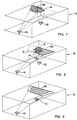
- Figures 3-8 are perspective views of the alignment technique according to the present invention.
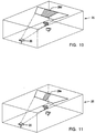
- Figures 9-11 are perspective views of an alternate alignment technique.
- Figure 12 shows a flow chart for gaining entry permission according to the present invention.
- the first is proper alignment between all of the residents so that each resident can communicate with every other resident.
- the second is permission to enter after proper alignment has been achieved.
- each of the LEDs in the transmitter portion of transceiver 20 transmits a portion of the entire illumination spot 28 on the ceiling of the room 26. All eight of the LEDs are flashed simultaneously during data transmission to increase the intensity and size of the illuminated spot and thereby reduce or eliminate transmission of errors. Nevertheless, it is possible to activate any one or group of these LEDs as desired.
- FIG 3 shows transceiver 20 located within room 26.
- Transceiver 20 projects illumination spot 28a using only the right four of its eight infrared LEDs.
- Figure 4 shows transceiver 20 projecting illumination spot 28b using only the left four of its eight LEDs.
- Each transceiver is designed so that the view of its photosensitive receiver is approximately identical to the illumination projection of its entire array of LEDs. Accordingly, the illumination projection 30 for transceiver 22 is approximately identical to the field of view which the receiving portion of transceiver 22 senses. For purposes of this explanation, it will be assumed that the transmission and receiving fields of view are identical for each transceiver. Accordingly, illumination spot 30 is also the field of view for transceiver 22.
- FIG 5 shows transceiver 22 with its illumination projection 30 and transceiver 20 with its right half illumination projection 28a.
- the field of view 30 for transceiver 22 is entirely within the right half illumination projection 28a for transceiver 20.
- Figure 6 shows that the field of view 30 is completely out of the left half illumination projection 28b for transceiver 20.
- transceiver 20 will toggle between left and right half transmissions while transceiver 22 looks within its field of view 30. While transmitting only left and right half illumination projections transceiver 20 can transmit appropriate information to indicate that only the left or right half of the array of LEDs is being utilized as appropriate. This information can be used to help center the field of view 30 for transceiver 22 as shown in Figure 7.
- One method of presenting the person aligning a unit with information useful in achieving proper alignment is to provide an indication of average received signal strength. Such an indication may be provided by the relative brightness of a visible light emitting diode.
- a new unit As a new unit is aimed at different portions of the illumination projection it will receive varying amplitude signals.
- the amplitude of these signals may be used to produce a varying level of current through a visible light emitting diode, thus producing varying brightness.
- the perceived brightness of the visible light emitting diode depends both on the magnitude of the current passing through it and the percentage of time during which the current flows. Thus two different types of information may be simultaneously provided to assist the user in aligning a unit.
- a transceiver such as transceiver 22 receives a relatively small portion of the illumination projection provided by transceiver 20. Since transceiver 22 is located relatively close to the center of the illumination projection, it receives a relatively stronger signal than units located at greater distances. By properly shaping the relationship between received signal strength and the current level flowing though the visible light emitting diode, it is possible to make the relative perceived brightness of the visible light emitting diode more dependent on the percentage of time during which the current flows than on the received signal strength variations. This is appropriate at high received signal levels and yields an aiming indication which varies approximately in proportion to the degree angular alignment.
- the shaping of the relationship between received signal strength and the current level flowing through the visible light emitting diode will produce a more linear relationship than at stronger signal levels.
- the perceived brightness of the visible light emitting diode will depend on both the percentage of time during which the current flows and on the received signal strength variations. This provides the necessary alignment information to the person aligning the more distant unit to a distant transceiver's illumination projection.
- the illumination projection and field of view 32 of transceiver 24 can be centrally aligned to illumination projection 28 of transceiver 20 as shown in Figure 8. This alignment can be repeated for each new resident that is added onto the network.
- FIG. 9 the outer two LEDs of transceiver 20 have been turned off forming illumination projection 28c.
- Figure 10 shows that the outer two LEDs at each end have been turned off forming illumination projection d.
- Figure 11 shows that the three LEDs at each end have been turned off forming illumination projection 28e.
- this technique can be used to align the illumination projection or field of view of multiple infrared transceivers to one another. As a new resident is brought into an existing network or as the first resident on a new network is brought into operation, that new member will look into its field of view for an infrared information transmission. A new resident will not transmit before observing in its field of view so that it will not cause a collision on the network.
- the announcement includes four messages:
- Number “3” now knows that there are two residents on the network. Number “3” must remain silent until it can see all the announced members on the list, i.e. both number “1” and number “2". Until that time number “3" does not have permission to enter the network. Once number “3” becomes properly aligned it can see both number “1” and number “2” announce their full messages. After number “2" has completed its full message, resident number “3” will then announce:
- Resident number "1" and resident number "2" will then both amend their list of valid residents to include resident number "3". If one of the residents drops out of the network for some reason the list of valid residents on the network for each remaining resident is amended to delete that number. Each remaining resident maintains their original valid resident number.
- a single lens with two LEDs will be positioned on the outside of the box for the aligning person to see.
- One LED will be red and the other will be green.
- the red LED will be illuminated.
- the red light is extinguished and the green light is illuminated.
- Another alternate embodiment for improved ease of alignment is to mount a receiver on either side of the transceiving apparatus.
- the phase difference measured between these two receivers can be used to properly align the transceiver to the network, in the azimuth plane.
- the amplitude difference in their received signals can be used to properly align the transceiver to the network in the elevation plane.
- a method and apparatus has been disclosed for aligning residents to a network having infrared as the communication medium.
Landscapes
- Engineering & Computer Science (AREA)
- Physics & Mathematics (AREA)
- Electromagnetism (AREA)
- Computer Networks & Wireless Communication (AREA)
- Signal Processing (AREA)
- Computing Systems (AREA)
- Optical Communication System (AREA)
- Small-Scale Networks (AREA)
- Mobile Radio Communication Systems (AREA)
Claims (3)
- Netz, wobei Infrarotübertragung das zum Verbinden von Teilnehmern (20, 22, 24) in dem Netz benutzte Medium ist und wobei jeder Teilnehmer (20, 22, 24) in dem Netz, der Information sendet, einen Infrarotsender mit einer Reihenanordnung von Sendequellen hat, gekennzeichnet durch:a. eine Einrichtung zum Ausrichten jedes Teilnehmers, um ihn dazu zu befähigen, mit jedem anderen Teilnehmer zu kommunizieren, wobei die Einrichtung zum Ausrichten jedes Teilnehmers dafür ausgebildet ist, einen ersten Teil einer Reihe von Sendequellen abwechselnd zu aktivieren, der etwa die Hälfte der Sendequellen an einem Ende der Reihe umfaßt, und dann die übrigen Sendequellen zu aktivieren; undb. eine Einrichtung, um einem voraussichtlichen neuen Teilnehmer die Zulassung zum Eintreten in das Infrarotnetz oder zum Senden von Information über das Infrarotnetz zu verweigern, bis dieser Teilnehmer jeden in dem Netz vorhandenen Teilnehmer erkennen und mit ihm kommunizieren kann.
- Verfahren zum Ausrichten mehrerer Teilnehmer (20, 22, 24) eines Netzes, wobei das Kommunikationsmedium für das Netz Infrarotstrahlung ist und jeder Teilnehmer (20, 22, 24), der Information sendet, einen Infrarotsender mit einer Reihenanordnung von Sendequellen hat, gekennzeichnet durch:a) abwechselndes Aktivieren eines Teils der Sendequellen für jeden Sender;b) Sicherstellen, daß jeder Sender (20, 22, 24) jede Teilsendung erkennen kann;c) Verhindern, daß ein voraussichtlicher neuer Teilnehmer in das Netz eintreten kann, bis er jede Teilsendung erkennen kann;d) Erteilen der Zulassung einem voraussichtlichen neuen Teilnehmer zu dem Netz, nachdem er jede Teilsendung erkennen kann;e) Veranlassen, daß ein voraussichtlicher neuer Teilnehmer ankündigt, daß er dem Netz beitritt, nachdem er überprüft hat, daß er mit jedem anderen Teilnehmer kommunizieren kann;f) Veranlassen, daß jeder Teilnehmer (20, 22, 24) des Netes periodisch ankündigt, daß er ein Teilnehmer ist, und jeden Teilnehmer, den er erkennt, identifiziert; undg) Veranlassen, daß ein Teilnehmer (20, 22, 24) weiteres Senden abbricht, wenn es ihm nicht mehr gelingt, jede Teilsendung zu erkennen.
- Verfahren zum Ausrichten von Teilnehmern eines Netzes, das ein Kommunikationsmedium in Form von Infrarotstrahlung hat, dadurch gekennzeichnet, daß ein Teilnehmer (20) wenigstens zwei voneinander beabstandete Empfänger hat zum Empfangen eines reflektierten Strahlungssignals durch Erfassen der Amplituden- und Phasendifferenz zwischen dem durch jeden Empfänger empfangenen Strahlungssignal zum Ausrichten des Teilnehmers (20) in der Elevations- und in der Azimutebene mit dem reflektierten Strahlungssignal.
Applications Claiming Priority (3)
| Application Number | Priority Date | Filing Date | Title |
|---|---|---|---|
| US07/331,607 US5119226A (en) | 1989-03-30 | 1989-03-30 | Infrared network entry permission apparatus |
| US331607 | 1989-03-30 | ||
| PCT/US1990/001566 WO1990012462A1 (en) | 1989-03-30 | 1990-03-22 | Infrared network entry permission method and apparatus |
Publications (3)
| Publication Number | Publication Date |
|---|---|
| EP0465604A1 EP0465604A1 (de) | 1992-01-15 |
| EP0465604A4 EP0465604A4 (en) | 1992-07-01 |
| EP0465604B1 true EP0465604B1 (de) | 1996-08-28 |
Family
ID=23294649
Family Applications (1)
| Application Number | Title | Priority Date | Filing Date |
|---|---|---|---|
| EP90907934A Expired - Lifetime EP0465604B1 (de) | 1989-03-30 | 1990-03-22 | Eingangszulassungsapparat in einem infraroten netz und verfahren |
Country Status (5)
| Country | Link |
|---|---|
| US (1) | US5119226A (de) |
| EP (1) | EP0465604B1 (de) |
| JP (1) | JPH0771039B2 (de) |
| DE (1) | DE69028301T2 (de) |
| WO (1) | WO1990012462A1 (de) |
Families Citing this family (17)
| Publication number | Priority date | Publication date | Assignee | Title |
|---|---|---|---|---|
| USD351158S (en) | 1992-03-10 | 1994-10-04 | Photonics Corporation | Infrared digital transceiver |
| US5371623A (en) * | 1992-07-01 | 1994-12-06 | Motorola, Inc. | High bit rate infrared communication system for overcoming multipath |
| US5602667A (en) * | 1992-10-07 | 1997-02-11 | Unisys Corporation | Extended distance fiber optic interface |
| JP3205127B2 (ja) * | 1993-06-22 | 2001-09-04 | キヤノン株式会社 | 通信制御方法及びその装置 |
| DE19728501A1 (de) * | 1997-07-03 | 1999-01-07 | Hertz Inst Heinrich | Vorrichtung zur drahtlosen Datenübertragung |
| US6985451B1 (en) | 1997-10-14 | 2006-01-10 | Alvarion Israel (2003) Ltd. | Method and apparatus for baseband transmission between a top floor unit and an outdoor unit in a terminal for a wireless metropolitan area network |
| US6907048B1 (en) | 1997-10-14 | 2005-06-14 | Alvarion Israel (2003) Ltd. | Method and apparatus for transporting ethernet data packets via radio frames in a wireless metropolitan area network |
| US6539031B1 (en) | 1997-10-14 | 2003-03-25 | Innowave Eci Wireless Systems Ltd. | Adaptive countermeasures for wireless communication of fast ethernet data packages |
| US7002941B1 (en) | 1997-10-14 | 2006-02-21 | Alvarion Israel (2003) Ltd. | Method and apparatus for synchronizing fast ethernet data packets to radio frames in a wireless metropolitan area network |
| US6665285B1 (en) | 1997-10-14 | 2003-12-16 | Alvarion Israel (2003) Ltd. | Ethernet switch in a terminal for a wireless metropolitan area network |
| US6480477B1 (en) | 1997-10-14 | 2002-11-12 | Innowave Eci Wireless Systems Ltd. | Method and apparatus for a data transmission rate of multiples of 100 MBPS in a terminal for a wireless metropolitan area network |
| DK2278744T3 (da) | 1997-10-14 | 2013-10-28 | Wi Lan Inc | Fremgangsmåde og apparat til opretholdelse af en forhåndsdefineret transmissionskvalitet i et trådløst MAN-netværk |
| US7071814B1 (en) * | 2000-07-31 | 2006-07-04 | Motorola, Inc. | Contextually aware network announcements of people |
| US20020163699A1 (en) * | 2001-02-16 | 2002-11-07 | The Penn State Research Foundation | Wireless infrared multi-spot diffusing communication system |
| US8401395B2 (en) * | 2009-11-16 | 2013-03-19 | Verizon Patent And Licensing Inc. | Free space optics broadband home network |
| EP3017555B1 (de) * | 2013-07-01 | 2020-10-28 | Nokia Technologies Oy | Gerichtete optische kommunikationen |
| US10783026B2 (en) * | 2018-02-15 | 2020-09-22 | Honeywell International Inc. | Apparatus and method for detecting network problems on redundant token bus control network using traffic sensor |
Family Cites Families (8)
| Publication number | Priority date | Publication date | Assignee | Title |
|---|---|---|---|---|
| US4330204A (en) * | 1979-11-16 | 1982-05-18 | Santa Barbara Research Center | Self-aligning laser communicator utilizing reciprocal tracking |
| US4506360A (en) * | 1982-03-29 | 1985-03-19 | Gould Inc. | Multi-station token pass communication system and method |
| JPS59235A (ja) * | 1982-06-25 | 1984-01-05 | Yokogawa Hokushin Electric Corp | 通信システム |
| JPS6123427A (ja) * | 1984-07-11 | 1986-01-31 | Matsushita Electric Ind Co Ltd | 情報伝達装置 |
| US4778238A (en) * | 1985-08-01 | 1988-10-18 | Hicks John W | Optical communications systems and process for signal amplification using stimulated brillouin scattering (SBS) and laser utilized in the system |
| JPH0797762B2 (ja) * | 1986-08-29 | 1995-10-18 | エスエムケイ株式会社 | 空間伝搬光通信における中継方法 |
| EP0290934B1 (de) * | 1987-05-14 | 1994-01-19 | Siemens Aktiengesellschaft | Verfahren zum Bilden einer Adressentabelle in einem ringförmigen Kommunikationsnetz |
| JPH01215139A (ja) * | 1988-02-23 | 1989-08-29 | Takenaka Komuten Co Ltd | 光通信システム |
-
1989
- 1989-03-30 US US07/331,607 patent/US5119226A/en not_active Expired - Fee Related
-
1990
- 1990-03-22 WO PCT/US1990/001566 patent/WO1990012462A1/en not_active Ceased
- 1990-03-22 DE DE69028301T patent/DE69028301T2/de not_active Expired - Fee Related
- 1990-03-22 EP EP90907934A patent/EP0465604B1/de not_active Expired - Lifetime
- 1990-03-22 JP JP2506754A patent/JPH0771039B2/ja not_active Expired - Lifetime
Also Published As
| Publication number | Publication date |
|---|---|
| JPH04504343A (ja) | 1992-07-30 |
| JPH0771039B2 (ja) | 1995-07-31 |
| WO1990012462A1 (en) | 1990-10-18 |
| DE69028301D1 (de) | 1996-10-02 |
| US5119226A (en) | 1992-06-02 |
| DE69028301T2 (de) | 1997-01-23 |
| EP0465604A1 (de) | 1992-01-15 |
| EP0465604A4 (en) | 1992-07-01 |
Similar Documents
| Publication | Publication Date | Title |
|---|---|---|
| US5245460A (en) | Infrared network entry permission method and apparatus | |
| US5119226A (en) | Infrared network entry permission apparatus | |
| US4977618A (en) | Infrared data communications | |
| EP3928443B1 (de) | Verfahren und system zur kommunikation mittels lichtsignalen | |
| US7421338B2 (en) | Robot system | |
| US20240430008A1 (en) | Contention-based access for optical wireless communication systems | |
| CN113405551A (zh) | 一种基于区域划分的自适应可见光室内定位方法 | |
| US7294822B2 (en) | Method and apparatus to communicate with and individually locate multiple remote devices on a two-dimensional surface | |
| CN114762273B (zh) | 一种计算设备 | |
| US5650868A (en) | Data transfer system | |
| US20200083957A1 (en) | A wireless communication link between at least one communication terminal device positioned in a predeterminable region and a communication network | |
| JP3022425B2 (ja) | 送受信光学装置 | |
| JPH10178393A (ja) | 光送受信装置 | |
| JP2007324672A (ja) | 照明光通信システムおよび端末装置 | |
| CN113163351B (zh) | 一种多级基站定位系统及方法 | |
| JP2007324671A (ja) | 照明光通信装置 | |
| JPH05206946A (ja) | 光空間伝送システム | |
| JPH0797762B2 (ja) | 空間伝搬光通信における中継方法 | |
| JPH043139B2 (de) | ||
| JPS6253032A (ja) | 光フアイバ双方向伝送方式 | |
| JPS5887932A (ja) | 空間ビ−ム通信システム | |
| JPH0797763B2 (ja) | 空間伝搬光通信における中継方法 | |
| JPH05206947A (ja) | 光空間伝送システム | |
| JPS6295033A (ja) | 光信号送信システム | |
| JPH05167537A (ja) | 光空間伝送装置 |
Legal Events
| Date | Code | Title | Description |
|---|---|---|---|
| PUAI | Public reference made under article 153(3) epc to a published international application that has entered the european phase |
Free format text: ORIGINAL CODE: 0009012 |
|
| 17P | Request for examination filed |
Effective date: 19910924 |
|
| AK | Designated contracting states |
Kind code of ref document: A1 Designated state(s): DE FR GB IT |
|
| RIN1 | Information on inventor provided before grant (corrected) |
Inventor name: ALLEN, RICHARD, C. Inventor name: STEWART, BERNARD, E. Inventor name: PICCONE, JOHN Inventor name: GRADY, ROBERT, J. Inventor name: JANIS, LOUIS, R. |
|
| A4 | Supplementary search report drawn up and despatched |
Effective date: 19920508 |
|
| AK | Designated contracting states |
Kind code of ref document: A4 Designated state(s): DE FR GB IT |
|
| 17Q | First examination report despatched |
Effective date: 19941216 |
|
| GRAG | Despatch of communication of intention to grant |
Free format text: ORIGINAL CODE: EPIDOS AGRA |
|
| GRAH | Despatch of communication of intention to grant a patent |
Free format text: ORIGINAL CODE: EPIDOS IGRA |
|
| GRAH | Despatch of communication of intention to grant a patent |
Free format text: ORIGINAL CODE: EPIDOS IGRA |
|
| GRAA | (expected) grant |
Free format text: ORIGINAL CODE: 0009210 |
|
| AK | Designated contracting states |
Kind code of ref document: B1 Designated state(s): DE FR GB IT |
|
| PG25 | Lapsed in a contracting state [announced via postgrant information from national office to epo] |
Ref country code: IT Free format text: LAPSE BECAUSE OF FAILURE TO SUBMIT A TRANSLATION OF THE DESCRIPTION OR TO PAY THE FEE WITHIN THE PRE;WARNING: LAPSES OF ITALIAN PATENTS WITH EFFECTIVE DATE BEFORE 2007 MAY HAVE OCCURRED AT ANY TIME BEFORE 2007. THE CORRECT EFFECTIVE DATE MAY BE DIFFERENT FROM THE ONE RECORDED.SCRIBED TIME-LIMIT Effective date: 19960828 Ref country code: FR Effective date: 19960828 |
|
| REF | Corresponds to: |
Ref document number: 69028301 Country of ref document: DE Date of ref document: 19961002 |
|
| EN | Fr: translation not filed | ||
| PGFP | Annual fee paid to national office [announced via postgrant information from national office to epo] |
Ref country code: GB Payment date: 19970324 Year of fee payment: 8 |
|
| PGFP | Annual fee paid to national office [announced via postgrant information from national office to epo] |
Ref country code: DE Payment date: 19970326 Year of fee payment: 8 |
|
| PLBE | No opposition filed within time limit |
Free format text: ORIGINAL CODE: 0009261 |
|
| STAA | Information on the status of an ep patent application or granted ep patent |
Free format text: STATUS: NO OPPOSITION FILED WITHIN TIME LIMIT |
|
| 26N | No opposition filed | ||
| PG25 | Lapsed in a contracting state [announced via postgrant information from national office to epo] |
Ref country code: GB Free format text: LAPSE BECAUSE OF NON-PAYMENT OF DUE FEES Effective date: 19980322 |
|
| GBPC | Gb: european patent ceased through non-payment of renewal fee |
Effective date: 19980322 |
|
| PG25 | Lapsed in a contracting state [announced via postgrant information from national office to epo] |
Ref country code: DE Free format text: LAPSE BECAUSE OF NON-PAYMENT OF DUE FEES Effective date: 19981201 |