EP0465455B1 - Verbindungsbügel für vorgefertigte, selbsttragende Bauteile - Google Patents
Verbindungsbügel für vorgefertigte, selbsttragende Bauteile Download PDFInfo
- Publication number
- EP0465455B1 EP0465455B1 EP19910870107 EP91870107A EP0465455B1 EP 0465455 B1 EP0465455 B1 EP 0465455B1 EP 19910870107 EP19910870107 EP 19910870107 EP 91870107 A EP91870107 A EP 91870107A EP 0465455 B1 EP0465455 B1 EP 0465455B1
- Authority
- EP
- European Patent Office
- Prior art keywords
- connecting bar
- beams
- superimposed
- upper face
- leg
- Prior art date
- Legal status (The legal status is an assumption and is not a legal conclusion. Google has not performed a legal analysis and makes no representation as to the accuracy of the status listed.)
- Expired - Lifetime
Links
- 238000010276 construction Methods 0.000 description 8
- 239000002184 metal Substances 0.000 description 6
- 229910052751 metal Inorganic materials 0.000 description 6
- 239000002023 wood Substances 0.000 description 6
- XEEYBQQBJWHFJM-UHFFFAOYSA-N Iron Chemical compound [Fe] XEEYBQQBJWHFJM-UHFFFAOYSA-N 0.000 description 4
- 238000000034 method Methods 0.000 description 4
- 238000006073 displacement reaction Methods 0.000 description 3
- 238000005553 drilling Methods 0.000 description 2
- 229910052742 iron Inorganic materials 0.000 description 2
- 238000004519 manufacturing process Methods 0.000 description 2
- 230000003014 reinforcing effect Effects 0.000 description 2
- 229920002994 synthetic fiber Polymers 0.000 description 2
- 208000031968 Cadaver Diseases 0.000 description 1
- 229910000831 Steel Inorganic materials 0.000 description 1
- 238000009434 installation Methods 0.000 description 1
- 238000002360 preparation method Methods 0.000 description 1
- 239000010959 steel Substances 0.000 description 1
Images

Classifications
-
- E—FIXED CONSTRUCTIONS
- E04—BUILDING
- E04B—GENERAL BUILDING CONSTRUCTIONS; WALLS, e.g. PARTITIONS; ROOFS; FLOORS; CEILINGS; INSULATION OR OTHER PROTECTION OF BUILDINGS
- E04B2/00—Walls, e.g. partitions, for buildings; Wall construction with regard to insulation; Connections specially adapted to walls
- E04B2/56—Load-bearing walls of framework or pillarwork; Walls incorporating load-bearing elongated members
- E04B2/70—Load-bearing walls of framework or pillarwork; Walls incorporating load-bearing elongated members with elongated members of wood
- E04B2/701—Load-bearing walls of framework or pillarwork; Walls incorporating load-bearing elongated members with elongated members of wood with integrated supporting and obturation function
- E04B2/704—Load-bearing walls of framework or pillarwork; Walls incorporating load-bearing elongated members with elongated members of wood with integrated supporting and obturation function with longitudinal horizontal elements shorter than the length of a wall
-
- E—FIXED CONSTRUCTIONS
- E04—BUILDING
- E04B—GENERAL BUILDING CONSTRUCTIONS; WALLS, e.g. PARTITIONS; ROOFS; FLOORS; CEILINGS; INSULATION OR OTHER PROTECTION OF BUILDINGS
- E04B2/00—Walls, e.g. partitions, for buildings; Wall construction with regard to insulation; Connections specially adapted to walls
- E04B2/02—Walls, e.g. partitions, for buildings; Wall construction with regard to insulation; Connections specially adapted to walls built-up from layers of building elements
- E04B2/04—Walls having neither cavities between, nor in, the solid elements
- E04B2/06—Walls having neither cavities between, nor in, the solid elements using elements having specially-designed means for stabilising the position
- E04B2/08—Walls having neither cavities between, nor in, the solid elements using elements having specially-designed means for stabilising the position by interlocking of projections or inserts with indentations, e.g. of tongues, grooves, dovetails
-
- E—FIXED CONSTRUCTIONS
- E04—BUILDING
- E04B—GENERAL BUILDING CONSTRUCTIONS; WALLS, e.g. PARTITIONS; ROOFS; FLOORS; CEILINGS; INSULATION OR OTHER PROTECTION OF BUILDINGS
- E04B2/00—Walls, e.g. partitions, for buildings; Wall construction with regard to insulation; Connections specially adapted to walls
- E04B2/02—Walls, e.g. partitions, for buildings; Wall construction with regard to insulation; Connections specially adapted to walls built-up from layers of building elements
- E04B2002/0202—Details of connections
- E04B2002/0204—Non-undercut connections, e.g. tongue and groove connections
- E04B2002/0208—Non-undercut connections, e.g. tongue and groove connections of trapezoidal shape
-
- E—FIXED CONSTRUCTIONS
- E04—BUILDING
- E04B—GENERAL BUILDING CONSTRUCTIONS; WALLS, e.g. PARTITIONS; ROOFS; FLOORS; CEILINGS; INSULATION OR OTHER PROTECTION OF BUILDINGS
- E04B2/00—Walls, e.g. partitions, for buildings; Wall construction with regard to insulation; Connections specially adapted to walls
- E04B2/02—Walls, e.g. partitions, for buildings; Wall construction with regard to insulation; Connections specially adapted to walls built-up from layers of building elements
- E04B2002/0202—Details of connections
- E04B2002/0204—Non-undercut connections, e.g. tongue and groove connections
- E04B2002/0228—Non-undercut connections, e.g. tongue and groove connections with tongues next to each other on one end surface and grooves next to each other on opposite end surface
-
- E—FIXED CONSTRUCTIONS
- E04—BUILDING
- E04B—GENERAL BUILDING CONSTRUCTIONS; WALLS, e.g. PARTITIONS; ROOFS; FLOORS; CEILINGS; INSULATION OR OTHER PROTECTION OF BUILDINGS
- E04B2/00—Walls, e.g. partitions, for buildings; Wall construction with regard to insulation; Connections specially adapted to walls
- E04B2/02—Walls, e.g. partitions, for buildings; Wall construction with regard to insulation; Connections specially adapted to walls built-up from layers of building elements
- E04B2002/0202—Details of connections
- E04B2002/0243—Separate connectors or inserts, e.g. pegs, pins or keys
- E04B2002/0245—Pegs or pins
Definitions
- the invention relates to a connecting bracket made of a metal or synthetic material rod, bent at a right angle for making corners.
- It also relates to a method for making or reinforcing a corner in a prefabricated self-supporting construction, in particular in prefabricated constructions for habitation, masts and garden houses whose walls are formed of beams or logs arranged one at a time. above others.
- Document BE-A-871.546 discloses a metal corner piece for prefabricated housing, and more particularly for masts whose walls are formed by superimposed beams.
- Each beam is provided along its upper edge by a longitudinal projecting edge, while the lower edge is provided with a groove which cooperates with the projecting edge to form an assembly of the tenon and mortise type.
- This construction has the drawback of facilitating the splitting of wood already during the slightest movement or displacement of beams or walls.
- the present invention aims to remedy this drawback and proposes a corner construction which allows rapid assembly of the walls, so to speak without preparations. It relates to a connecting bracket made up of a metal or synthetic material rod, bent at a right angle for the production of corner joints, characterized in that it comprises three consecutive straight elbows which extend perpendicularly to one another. other in planes perpendicular to each other, so as to form adjacent squares which stand perpendicular to each other in orthogonal dihedrons.
- the steel rod is a concrete iron. In this way the production costs become approximately cheaper by about a third compared to those of the corner fittings comprising two flanges perpendicular to each other.
- the connecting stirrup has legs of equal length.
- the connecting stirrup according to the invention is very easily manufactured using a folding machine common in the building sector.
- the mounting of the connecting bracket is also easy.
- the preparatory work is limited to drilling only one hole in each of the concurrent beams at a very precise distance from the end of each beam.
- One leg of the square is pushed completely into a hole until the body of the connecting piece is embedded in a mortise of the beam.
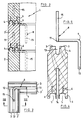
- the walls 1 of a self-supporting construction are formed of beams wood 2, 2 'which are arranged one above the other.
- the beams 2,2 ′ are provided on their upper face with two projecting edges 3, 3 ′ arranged lengthwise and whose edges 4 are bevelled, while the lower face of each beam 2, 2 ′ provided with two grooves 5, 5 'is placed on the edges 3, 3' of a lower beam 2 and they can cooperate so as to form a connection of the tenon and mortise type in order to prevent the lateral sliding of the two beams 2 l ' one relative to the other (see also Figure 4).
- a groove 6 is provided on either side of the groove 5 to give elasticity to the edges 7 of the groove 5.
- the connecting stirrup 8 is formed of a metal rod bent at a right angle, in particular a concrete iron of the type generally used in the building industry (FIG. 5).
- the rod comprises three consecutive straight elbows 9, 10, 11 which extend perpendicular to one another in planes perpendicular to each other, so as to form adjacent brackets which stand perpendicular to each other.
- Two adjoining elbows are included in planes which stand perpendicular to each other and form a right dihedral.
- the depth of the groove 5 is greater than the height of the edge 3 so that after having superimposed two beams, a suitable gap is maintained between the tenon and the mortise for the mounting of the connecting bracket 8 according to l 'invention.
- a hole 14 is provided in the bottom of the groove 5, 5 ′ of each beam 2, at a precise distance from the corner.
- a leg 15 of the connecting stirrup according to the invention is introduced into the hole 14 until the first and the second elbow 9, 10 are underlying converging or concurrent beams. Only the beams arranged perpendicular to each other are connected by a connecting stirrup.
- the connecting bracket gives great rigidity to the corner without causing tension in the wooden beams.
- Each hole 14 formed in the beam 2 is optionally provided with a conical edge 16 to facilitate the introduction of a leg 15 of the connecting stirrup 8.
- the leg 15 of the connecting stirrup 8 is pressed in. using a hammer on the first elbow until the body drowns in the two grooves that form the corner.
Landscapes
- Engineering & Computer Science (AREA)
- Architecture (AREA)
- Physics & Mathematics (AREA)
- Electromagnetism (AREA)
- Civil Engineering (AREA)
- Structural Engineering (AREA)
- Joining Of Building Structures In Genera (AREA)
Claims (7)
- Verbindungsbügel bestehend aus einer zur Bildung von Eckwinkeln rechtwinklig gebogenen Stange aus Metall oder Kunststoffmaterial, dadurch gekennzeichnet, daß er drei aufeinanderfolgende rechtwinklige Bögen (9, 10, 11) aufweist, die in zueinander senkrechten Ebenen zueinander senkrecht derart verlaufen, daß sie benachbarte Winkelstücke bilden, die senkrecht zueinander in orthogonale Dieder passen.
- Verbindungsbügel nach Anspruch 1, dadurch gekennzeichnet, daß die Metallstange ein Betoneisen ist.
- Verbindungsbügel nach einem der vorhergehenden Ansprüche, dadurch gekennzeichnet, daß die benachbarten Bögen (9, 10, 11) Schenkel (15) gleicher Länge aufweisen.
- Verbindungsbügel nach einem der vorhergehenden Ansprüche, dadurch gekennzeichnet, daß die Länge eines Schenkels (15) der Metallstange wenigstens gleich der Hälfte der Höhe des Trägers (2) ist.
- Verfahren zum Verstärken eines Eckwinkels einer selbsttragenden Konstruktion, bei der die Wände aus übereinandergelegten Trägern gebildet sind, deren Oberseite mit einer Nut (13) versehen sind, unter Verwendung eines Verbindungsbügels nach einem der vorhergehenden Ansprüche, gekennzeichnet durch die folgenden Schritte:1) Bohren eines einzelnen Lochs in der Oberseite oder der Unterseite jedes Trägers (2) in vorbestimmter Entfernung von jedem Ende des Trägers (2);2) Einführen eines Schenkels (15) des Verbindungsbügels in das gebohrte Loch bis der Körper des Verbindungsbügels in den Nuten der sich kreuzenden oder schneidenden Träger eingesetzt ist; und3) Anordnen eines Trägers auf dem aufragenden Ende des Verbindungsbügels.
- Verfahren nach Anspruch 5, dadurch gekennzeichnet, daß die übereinandergelegten Träger (2) mittels einer Zapfenlochanordnung befestigt.
- Verfahren nach Anspruch 5 oder 6, dadurch gekennzeichnet, daß der Verbindungsbügel (8) in einem Zwischenraum (13) zwischen der Oberseite eines Stegs (3) und dem Boden einer Nut (5) zweier übereinanderliegender Träger (2, 2') angeordnet wird.
Applications Claiming Priority (2)
| Application Number | Priority Date | Filing Date | Title |
|---|---|---|---|
| BE9000688 | 1990-07-05 | ||
| BE9000688A BE1004503A6 (nl) | 1990-07-05 | 1990-07-05 | Verbindingsbeugel voor zelfdragend gebouw in systeembouw. |
Publications (2)
| Publication Number | Publication Date |
|---|---|
| EP0465455A1 EP0465455A1 (de) | 1992-01-08 |
| EP0465455B1 true EP0465455B1 (de) | 1995-02-01 |
Family
ID=3884861
Family Applications (1)
| Application Number | Title | Priority Date | Filing Date |
|---|---|---|---|
| EP19910870107 Expired - Lifetime EP0465455B1 (de) | 1990-07-05 | 1991-07-04 | Verbindungsbügel für vorgefertigte, selbsttragende Bauteile |
Country Status (2)
| Country | Link |
|---|---|
| EP (1) | EP0465455B1 (de) |
| BE (1) | BE1004503A6 (de) |
Families Citing this family (3)
| Publication number | Priority date | Publication date | Assignee | Title |
|---|---|---|---|---|
| US7661239B2 (en) * | 2003-10-17 | 2010-02-16 | Alliance Concrete Concepts Inc. | Masonry brick |
| FR2917105B1 (fr) * | 2007-06-05 | 2009-09-04 | Marc Simon Degorre | Jeu de madriers pour constructions de murs en bois. |
| BE1020097A5 (nl) * | 2010-10-08 | 2013-05-07 | Betaalbare Woning Nv De | Isolerende constructie voor de aanbouw van woningen en werkwijze hiervoor. |
Family Cites Families (1)
| Publication number | Priority date | Publication date | Assignee | Title |
|---|---|---|---|---|
| FR1270034A (fr) * | 1960-07-08 | 1961-08-25 | élément de construction préfabriqué |
-
1990
- 1990-07-05 BE BE9000688A patent/BE1004503A6/nl not_active IP Right Cessation
-
1991
- 1991-07-04 EP EP19910870107 patent/EP0465455B1/de not_active Expired - Lifetime
Also Published As
| Publication number | Publication date |
|---|---|
| BE1004503A6 (nl) | 1992-12-01 |
| EP0465455A1 (de) | 1992-01-08 |
Similar Documents
| Publication | Publication Date | Title |
|---|---|---|
| FR2529627A1 (fr) | Dispositif de fixation de pieces de montage a une paroi beton | |
| FR2570404A1 (fr) | Assemblage d'elements de type treteau pour agencements de plein air | |
| EP0465455B1 (de) | Verbindungsbügel für vorgefertigte, selbsttragende Bauteile | |
| EP2206855A1 (de) | Schalungspaneel für eine dünnen Betonschicht, Einheit aus zwei dieser Schlaungspaneelen sowie Verfahren zum Zusammenbauen dieser Schalungspaneelen | |
| FR2502671A1 (fr) | Dispositif de liaison pour planches d'echafaudages | |
| BE1003902A3 (fr) | Dispositif pour la liaison de poutres de constructions prefabriquees en treillis. | |
| EP1783302A2 (de) | Verbindungsmitteln eines Abstützbeines eine Gerüstes, Abstützbein eines Gerüstes mit solchen Verbindungsmitteln | |
| KR102157417B1 (ko) | 난간시스템 | |
| FR3057290A1 (fr) | Systeme de coffrage, organe de liaison specialement adapte pour un tel systeme de coffrage et procede de realisation d'une dalle d'un batiment mettant en œuvre un tel systeme de coffrage | |
| FR2500869A1 (fr) | Structure porteuse pour toitures ou hangars montables et demontables | |
| JP7326068B2 (ja) | 平行クランプ | |
| FR2861113A1 (fr) | Piece de liaison entre un poteau et une traverse et utilisation de cette piece de liaison pour la construction de clotures | |
| EP0440567A1 (de) | Einzelne und doppelte Träger und Pfosten, bestehend aus der Zusammensetzung von Z-Trägern, die insbesondere die Realisierung eines Rahmens oder einer Kniestütze für den Bau eines Gebäudes erlauben | |
| FR2718776A1 (fr) | Tôle de coffrage. | |
| FR2989398A1 (fr) | Dispositif de charpente metallique pour realiser des superstructures d'immeubles et des superstructures sommitales d'immeubles | |
| JP3668541B2 (ja) | 建材接続金具 | |
| US7311178B2 (en) | Work piece support hinge assembly | |
| FR2917104A1 (fr) | Assemblage de gabions juxtaposes et/ou superposes | |
| BE897841R (fr) | Palette a plancher | |
| EP1908897B1 (de) | Zaunanlage | |
| BE672249A (de) | ||
| FR2568297A1 (fr) | Coffrage metallique et procede pour couler un grand reservoir en beton a l'aide d'un tel coffrage | |
| FR2621340A1 (fr) | Charpente metallique | |
| FR2746432A1 (fr) | Dispositif de support pour un agencement formant plancher sur des parois peripheriques d'une structure | |
| CH368919A (fr) | Cloison |
Legal Events
| Date | Code | Title | Description |
|---|---|---|---|
| PUAI | Public reference made under article 153(3) epc to a published international application that has entered the european phase |
Free format text: ORIGINAL CODE: 0009012 |
|
| AK | Designated contracting states |
Kind code of ref document: A1 Designated state(s): BE CH ES LI |
|
| 17P | Request for examination filed |
Effective date: 19920625 |
|
| 17Q | First examination report despatched |
Effective date: 19930715 |
|
| GRAA | (expected) grant |
Free format text: ORIGINAL CODE: 0009210 |
|
| AK | Designated contracting states |
Kind code of ref document: B1 Designated state(s): BE CH ES LI |
|
| PG25 | Lapsed in a contracting state [announced via postgrant information from national office to epo] |
Ref country code: ES Free format text: THE PATENT HAS BEEN ANNULLED BY A DECISION OF A NATIONAL AUTHORITY Effective date: 19950201 |
|
| PG25 | Lapsed in a contracting state [announced via postgrant information from national office to epo] |
Ref country code: LI Effective date: 19950731 Ref country code: CH Effective date: 19950731 |
|
| PLBE | No opposition filed within time limit |
Free format text: ORIGINAL CODE: 0009261 |
|
| STAA | Information on the status of an ep patent application or granted ep patent |
Free format text: STATUS: NO OPPOSITION FILED WITHIN TIME LIMIT |
|
| 26N | No opposition filed | ||
| REG | Reference to a national code |
Ref country code: CH Ref legal event code: PL |
|
| PGFP | Annual fee paid to national office [announced via postgrant information from national office to epo] |
Ref country code: BE Payment date: 19980130 Year of fee payment: 7 |
|
| PG25 | Lapsed in a contracting state [announced via postgrant information from national office to epo] |
Ref country code: BE Free format text: LAPSE BECAUSE OF NON-PAYMENT OF DUE FEES Effective date: 19980731 |
|
| BERE | Be: lapsed |
Owner name: VANBEVEREN JACQUES Effective date: 19980731 |