EP0465413B1 - Vorrichtung für die Aufhängung von Zwischendecken - Google Patents
Vorrichtung für die Aufhängung von Zwischendecken Download PDFInfo
- Publication number
- EP0465413B1 EP0465413B1 EP91810478A EP91810478A EP0465413B1 EP 0465413 B1 EP0465413 B1 EP 0465413B1 EP 91810478 A EP91810478 A EP 91810478A EP 91810478 A EP91810478 A EP 91810478A EP 0465413 B1 EP0465413 B1 EP 0465413B1
- Authority
- EP
- European Patent Office
- Prior art keywords
- suspension
- anchorage
- suspension rod
- tunnel
- der
- Prior art date
- Legal status (The legal status is an assumption and is not a legal conclusion. Google has not performed a legal analysis and makes no representation as to the accuracy of the status listed.)
- Expired - Lifetime
Links
Images

Classifications
-
- E—FIXED CONSTRUCTIONS
- E21—EARTH OR ROCK DRILLING; MINING
- E21F—SAFETY DEVICES, TRANSPORT, FILLING-UP, RESCUE, VENTILATION, OR DRAINING IN OR OF MINES OR TUNNELS
- E21F1/00—Ventilation of mines or tunnels; Distribution of ventilating currents
- E21F1/003—Ventilation of traffic tunnels
-
- E—FIXED CONSTRUCTIONS
- E04—BUILDING
- E04B—GENERAL BUILDING CONSTRUCTIONS; WALLS, e.g. PARTITIONS; ROOFS; FLOORS; CEILINGS; INSULATION OR OTHER PROTECTION OF BUILDINGS
- E04B9/00—Ceilings; Construction of ceilings, e.g. false ceilings; Ceiling construction with regard to insulation
- E04B9/18—Means for suspending the supporting construction
- E04B9/20—Means for suspending the supporting construction adjustable
-
- E—FIXED CONSTRUCTIONS
- E21—EARTH OR ROCK DRILLING; MINING
- E21D—SHAFTS; TUNNELS; GALLERIES; LARGE UNDERGROUND CHAMBERS
- E21D11/00—Lining tunnels, galleries or other underground cavities, e.g. large underground chambers; Linings therefor; Making such linings in situ, e.g. by assembling
- E21D11/003—Linings or provisions thereon, specially adapted for traffic tunnels, e.g. with built-in cleaning devices
Definitions
- the present invention relates to a device for suspending false ceilings, in particular but not exclusively from false ceilings in tunnels, according to the preamble of patent claim 1.
- an intermediate ceiling is hung between the tunnel vault and the tunnel carriageway slab in order to separate the tunnel cross-section used by traffic from the cross-sections used by the ventilation and ventilation ducts and the other infrastructure ducts.
- the safety requirements placed on the suspensions used are very high.However, it must be ensured that even in the event of extraordinary occurrences and loads, the false ceiling does not fall onto the road surface, thereby endangering or even slamming tunnel users.
- the suspension In addition to ensuring the safety of tunnel users, the suspension must also have a durable construction.
- the present invention is therefore based on the object of providing a device for suspending false ceilings which meet all current and also expected future legal requirements.
- the suspension according to the invention should also be controllable and replaceable and not load-bearing Show welds. Furthermore, the pretensionability of the hanging rods and the non-destructive testing regarding corrosion by means of potential measurement should be guaranteed.
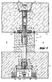
- FIG. 1 schematically shows a cross section through a tunnel vault 1, into which an intermediate ceiling 3 is suspended above the carriageway slab 2, parallel to it.
- the cavity between the tunnel vault 1 and false ceiling 3 is, as usual, through a vertical partition 4 in a ventilation and a ventilation channel 5, respectively. 6 divided.
- the false ceiling 3 is suspended from the tunnel vault 1 by means arranged in the intermediate wall 4 in the form of devices 7 according to the invention.
- the lateral connections 8 of the false ceiling 3 to the tunnel arch 1 are not taken into account in the context of the present invention, although they are important for the safety of the entire construction also play a significant role. The same also applies to the constructions of the tunnel vault 1 and the false ceiling 3 and the intermediate wall 4.
- the device 7 according to the invention for hanging the false ceiling 3 on the tunnel vault 1 essentially consists of three units, namely one upper anchoring 9 in the tunnel vault 1, a hanging unit 10 in the intermediate wall 4 and a lower anchoring 11 in the false ceiling 3.
- the structural details of these three units will be discussed in more detail below in connection with FIGS. 2 and 3.
- the upper anchoring 9 essentially consists of an advantageously cross-shaped anchoring bracket or pot 12 embedded in the tunnel vault concrete, to which a threaded sleeve 13 is connected, which extends into the region of the lower boundary of the concreted tunnel vault 1, where it joins with a lower end plate 14, advantageously by means of a screw 13 c, is connected.
- the end plate 14 is used, inter alia, in the manufacture of the tunnel arch 1 to nail the upper anchor 9 onto the formwork of the tunnel arch 1 by means of nail holes 15 provided for it.
- the end plate 14 serves as a stop for a pipe section 17 provided with a flange 16 and attachment by the pipe section 17 by means of set screws 18 which can be screwed into blind holes 20 provided with internal threads. Washers 19 are advantageously used for this purpose.
- connection of the anchoring bracket 12 with the threaded sleeve 13 is advantageously carried out by means of a threaded bolt 21 which, on the one hand, into an upper internal thread 13 a Threaded sleeve 13 is screwed and on the other hand, the anchoring bracket 12 is screwed from above by means of a nut 22 and a washer 23.
- a flexible hose 26 is advantageously inserted into these concrete parts, which extends from within the pipe section 17 down to a lower one, which is described in detail below Anchoring 11 connected pipe 27 extends.
- the lower anchor 11 which is embedded in the false ceiling 3 from below, essentially consists of a housing 28, advantageously with lateral reinforcing ribs 29, which serves as a receptacle for a ball joint plate 30.
- the latter is intended for interaction with a hemisphere 31 through which the hanging rod 24 passes and against which it is braced by means of a clamping nut 32 and advantageously a washer 33 and a lock nut 34.
- the inside diameter of the tube 27 is chosen larger on the one hand than that of the pipe section 17 and on the other hand, a seal 37 between the pipe 27 and hose 26 is provided.
- the housing 28 of the lower anchoring 11 is advantageously not axially symmetrical to the longitudinal axis of the hanging rod 24, but advantageously has an extension 38 on one side, which makes it easier to attach the wrench screwing the hanging rod 24 and tightening the clamping nut 32 and the lock nut 34 is used.
- a cover 40 is provided, which is advantageously provided in threaded blind holes 41 in the lateral reinforcing ribs 29 screw-in self-tapping screws 42 can be screwed tightly onto the housing 28 from below.
- the invention makes it possible to accommodate the suspension of the false ceiling 3 on the tunnel vault, completely isolated from the environment, essentially within concrete parts, without this making it impossible to check the load-bearing hanging rods 24. It is also essential that the invention makes it possible to individually pretension each hanging bar 24 and to load it with a predetermined load when the false ceiling 3 is suspended. As mentioned above, the invention also allows, to a certain extent, angular errors, which can arise, in particular, from an incorrect positioning of the upper anchor 9 in the tunnel vault 1, without compensating for the supporting parts.
- the device according to the invention is economical since even with varying Hanging height can be worked in a wide range with one and the same type of hanging bar.
- the person skilled in the art further recognizes that the ability to pretension the hanging rods 24 prevents the partition 3 from tearing off in the region of the tunnel arch 1 even in the event of fluctuations in load. As a result, it may be possible to dispense with the installation of a putty joint 43 at this point.
- the device according to the invention fulfills all the requirements placed on suspensions for false ceilings in tunnels and ensures that no load-bearing welds are present and that all parts of the false ceiling suspension that are critical in terms of safety can be checked at any time with relatively little effort and without destruction. It is economical and enables the individual parts to be largely standardized. It can also be used without problems with a false ceiling 3 designed as a vault, which increases the safety of the entire construction.
Landscapes
- Engineering & Computer Science (AREA)
- Mining & Mineral Resources (AREA)
- Architecture (AREA)
- Civil Engineering (AREA)
- Geochemistry & Mineralogy (AREA)
- Geology (AREA)
- General Life Sciences & Earth Sciences (AREA)
- Life Sciences & Earth Sciences (AREA)
- Structural Engineering (AREA)
- Physics & Mathematics (AREA)
- Electromagnetism (AREA)
- Lining And Supports For Tunnels (AREA)
- Supports Or Holders For Household Use (AREA)
- Mirrors, Picture Frames, Photograph Stands, And Related Fastening Devices (AREA)
Applications Claiming Priority (2)
| Application Number | Priority Date | Filing Date | Title |
|---|---|---|---|
| CH2265/90A CH681646A5 (enExample) | 1990-07-06 | 1990-07-06 | |
| CH2265/90 | 1990-07-06 |
Publications (2)
| Publication Number | Publication Date |
|---|---|
| EP0465413A1 EP0465413A1 (de) | 1992-01-08 |
| EP0465413B1 true EP0465413B1 (de) | 1995-03-15 |
Family
ID=4229729
Family Applications (1)
| Application Number | Title | Priority Date | Filing Date |
|---|---|---|---|
| EP91810478A Expired - Lifetime EP0465413B1 (de) | 1990-07-06 | 1991-06-20 | Vorrichtung für die Aufhängung von Zwischendecken |
Country Status (5)
| Country | Link |
|---|---|
| EP (1) | EP0465413B1 (enExample) |
| AT (1) | ATE119969T1 (enExample) |
| CH (1) | CH681646A5 (enExample) |
| DE (1) | DE59104942D1 (enExample) |
| ES (1) | ES2071964T3 (enExample) |
Families Citing this family (4)
| Publication number | Priority date | Publication date | Assignee | Title |
|---|---|---|---|---|
| DE102004038595A1 (de) * | 2004-08-06 | 2006-03-16 | Ed. Züblin Ag | Zwischendeckenkonstruktion im Tunnelbau und Verfahren zur Herstellung |
| KR101005605B1 (ko) | 2010-06-07 | 2011-02-07 | 김태균 | 아치형 프리캐스트 콘크리트 풍도 슬래브 및 이의 시공방법 |
| WO2013044433A1 (en) * | 2011-09-26 | 2013-04-04 | Empire Technology Development Llc | Suspension mould |
| AT14430U1 (de) * | 2014-07-08 | 2015-11-15 | Stu Stettin Hoch Und Tiefbau Gmbh | Vorrichtung zur abgehängten Befestigung einer Zwischendecke eines Tunnels |
Family Cites Families (1)
| Publication number | Priority date | Publication date | Assignee | Title |
|---|---|---|---|---|
| CH471287A (de) * | 1968-08-14 | 1969-04-15 | Beton Ag | Zwischendecken- und Trennwandkonstruktion für Tunnelbelüftungen |
-
1990
- 1990-07-06 CH CH2265/90A patent/CH681646A5/de not_active IP Right Cessation
-
1991
- 1991-06-20 AT AT91810478T patent/ATE119969T1/de not_active IP Right Cessation
- 1991-06-20 ES ES91810478T patent/ES2071964T3/es not_active Expired - Lifetime
- 1991-06-20 DE DE59104942T patent/DE59104942D1/de not_active Expired - Fee Related
- 1991-06-20 EP EP91810478A patent/EP0465413B1/de not_active Expired - Lifetime
Also Published As
| Publication number | Publication date |
|---|---|
| EP0465413A1 (de) | 1992-01-08 |
| ES2071964T3 (es) | 1995-07-01 |
| CH681646A5 (enExample) | 1993-04-30 |
| DE59104942D1 (de) | 1995-04-20 |
| ATE119969T1 (de) | 1995-04-15 |
Similar Documents
| Publication | Publication Date | Title |
|---|---|---|
| DE69613924T2 (de) | Variabel einzubettender Anker und Verfahren | |
| EP0465413B1 (de) | Vorrichtung für die Aufhängung von Zwischendecken | |
| DE69607395T2 (de) | A-förmige ankerschiene | |
| EP0697489A1 (de) | Trittschalldämmendes Auflagerelement | |
| EP0004345A1 (de) | Vorgespanntes Stahlbetonseil und Verfahren zur Anwendung von vorgespannten Stahlbetonseilen bei der Herstellung einer Hängebrücke | |
| EP2042657B1 (de) | Vorrichtung zur Verankerung von Kappen am Überbau von Bauwerken | |
| DE102023108875A1 (de) | Verfahren zum Herstellen einer Holz-Beton-Verbunddecke, Holz-Beton-Verbunddecke, Schraube und Markierungsteil | |
| DE2908405A1 (de) | Vorrichtung zum befestigen eines geruests an einer gebaeudewand | |
| EP0253141B1 (de) | Vorfabriziertes Bauelement sowie Treppenhaus | |
| EP2507450B1 (de) | Pfostenverankerung system züblin auf ingenieurbauwerken mit kugelscheiben-kegelpfannensystem | |
| AT286584B (de) | Auflager an senkrechten, tragenden Bauteilen | |
| DE29909395U1 (de) | Vorrichtung zur Eckbefestigung einer Leibungsplatte | |
| DE3305128A1 (de) | Momentdosierender, daempfungsfaehiger stuetz-traeger anschluss | |
| DE9307041U1 (de) | Horizontalträger für Bauwerke | |
| DE19738320B4 (de) | Kniestock-Wandelement zum Anbringen an industriell vorfertigbaren Gebäudeteilen | |
| CH676370A5 (en) | Anchor member for balustrade - consists of tube with central threaded section internally and non-threaded sections on both sides of that section | |
| DE29502816U1 (de) | Balkon | |
| DE8108672U1 (de) | Wiedergewinnbares schalungsteil fuer den verankerungsbereich eines spannglieds in einem betonbauteil | |
| DE2754371A1 (de) | Vorrichtung zur justierung und befestigung von messplatten, laufschienen u.dgl. | |
| DE2648477A1 (de) | Komplexer schachtausbau fuer den bergbau | |
| DE29713336U1 (de) | Tragelement | |
| DE9106281U1 (de) | Gerüstverankerungskonsole für die hinterlüfteten Fassaden | |
| EP0331642A2 (de) | Vorgefertigtes Eisenbeton-Bauelement | |
| DE202005004015U1 (de) | Befestigungsmittel für Geländer | |
| DE2264717A1 (de) | Verankerungsvorrichtung von gelaendern, leitplanken od. dgl. in bruecken od. dgl. |
Legal Events
| Date | Code | Title | Description |
|---|---|---|---|
| PUAI | Public reference made under article 153(3) epc to a published international application that has entered the european phase |
Free format text: ORIGINAL CODE: 0009012 |
|
| 17P | Request for examination filed |
Effective date: 19910715 |
|
| AK | Designated contracting states |
Kind code of ref document: A1 Designated state(s): AT BE CH DE DK ES FR GB IT LI LU NL SE |
|
| 17Q | First examination report despatched |
Effective date: 19931022 |
|
| GRAA | (expected) grant |
Free format text: ORIGINAL CODE: 0009210 |
|
| AK | Designated contracting states |
Kind code of ref document: B1 Designated state(s): AT BE CH DE DK ES FR GB IT LI LU NL SE |
|
| PG25 | Lapsed in a contracting state [announced via postgrant information from national office to epo] |
Ref country code: NL Free format text: LAPSE BECAUSE OF NON-PAYMENT OF DUE FEES Effective date: 19950315 Ref country code: DK Effective date: 19950315 Ref country code: BE Effective date: 19950315 |
|
| REF | Corresponds to: |
Ref document number: 119969 Country of ref document: AT Date of ref document: 19950415 Kind code of ref document: T |
|
| ITF | It: translation for a ep patent filed | ||
| REF | Corresponds to: |
Ref document number: 59104942 Country of ref document: DE Date of ref document: 19950420 |
|
| PG25 | Lapsed in a contracting state [announced via postgrant information from national office to epo] |
Ref country code: LU Free format text: LAPSE BECAUSE OF NON-PAYMENT OF DUE FEES Effective date: 19950630 |
|
| REG | Reference to a national code |
Ref country code: ES Ref legal event code: FG2A Ref document number: 2071964 Country of ref document: ES Kind code of ref document: T3 |
|
| ET | Fr: translation filed | ||
| GBT | Gb: translation of ep patent filed (gb section 77(6)(a)/1977) |
Effective date: 19950621 |
|
| NLV1 | Nl: lapsed or annulled due to failure to fulfill the requirements of art. 29p and 29m of the patents act | ||
| PLBE | No opposition filed within time limit |
Free format text: ORIGINAL CODE: 0009261 |
|
| 26N | No opposition filed | ||
| PGFP | Annual fee paid to national office [announced via postgrant information from national office to epo] |
Ref country code: GB Payment date: 19990611 Year of fee payment: 9 |
|
| PGFP | Annual fee paid to national office [announced via postgrant information from national office to epo] |
Ref country code: SE Payment date: 19990616 Year of fee payment: 9 Ref country code: FR Payment date: 19990616 Year of fee payment: 9 |
|
| PGFP | Annual fee paid to national office [announced via postgrant information from national office to epo] |
Ref country code: ES Payment date: 19990625 Year of fee payment: 9 |
|
| PG25 | Lapsed in a contracting state [announced via postgrant information from national office to epo] |
Ref country code: GB Free format text: LAPSE BECAUSE OF NON-PAYMENT OF DUE FEES Effective date: 20000620 |
|
| PG25 | Lapsed in a contracting state [announced via postgrant information from national office to epo] |
Ref country code: SE Free format text: LAPSE BECAUSE OF NON-PAYMENT OF DUE FEES Effective date: 20000621 Ref country code: ES Free format text: THE PATENT HAS BEEN ANNULLED BY A DECISION OF A NATIONAL AUTHORITY Effective date: 20000621 |
|
| PGFP | Annual fee paid to national office [announced via postgrant information from national office to epo] |
Ref country code: DE Payment date: 20000626 Year of fee payment: 10 |
|
| PGFP | Annual fee paid to national office [announced via postgrant information from national office to epo] |
Ref country code: AT Payment date: 20000629 Year of fee payment: 10 |
|
| GBPC | Gb: european patent ceased through non-payment of renewal fee |
Effective date: 20000620 |
|
| EUG | Se: european patent has lapsed |
Ref document number: 91810478.7 |
|
| PG25 | Lapsed in a contracting state [announced via postgrant information from national office to epo] |
Ref country code: FR Free format text: LAPSE BECAUSE OF NON-PAYMENT OF DUE FEES Effective date: 20010228 |
|
| REG | Reference to a national code |
Ref country code: FR Ref legal event code: ST |
|
| PG25 | Lapsed in a contracting state [announced via postgrant information from national office to epo] |
Ref country code: AT Free format text: LAPSE BECAUSE OF NON-PAYMENT OF DUE FEES Effective date: 20010620 |
|
| REG | Reference to a national code |
Ref country code: ES Ref legal event code: FD2A Effective date: 20020204 |
|
| PG25 | Lapsed in a contracting state [announced via postgrant information from national office to epo] |
Ref country code: DE Free format text: LAPSE BECAUSE OF NON-PAYMENT OF DUE FEES Effective date: 20020403 |
|
| PGFP | Annual fee paid to national office [announced via postgrant information from national office to epo] |
Ref country code: CH Payment date: 20030516 Year of fee payment: 13 |
|
| PG25 | Lapsed in a contracting state [announced via postgrant information from national office to epo] |
Ref country code: LI Free format text: LAPSE BECAUSE OF NON-PAYMENT OF DUE FEES Effective date: 20040630 Ref country code: CH Free format text: LAPSE BECAUSE OF NON-PAYMENT OF DUE FEES Effective date: 20040630 |
|
| REG | Reference to a national code |
Ref country code: CH Ref legal event code: PL |
|
| PG25 | Lapsed in a contracting state [announced via postgrant information from national office to epo] |
Ref country code: IT Free format text: LAPSE BECAUSE OF NON-PAYMENT OF DUE FEES;WARNING: LAPSES OF ITALIAN PATENTS WITH EFFECTIVE DATE BEFORE 2007 MAY HAVE OCCURRED AT ANY TIME BEFORE 2007. THE CORRECT EFFECTIVE DATE MAY BE DIFFERENT FROM THE ONE RECORDED. Effective date: 20050620 |