EP0465413B1 - Device for the suspension of intermediate ceilings - Google Patents
Device for the suspension of intermediate ceilings Download PDFInfo
- Publication number
- EP0465413B1 EP0465413B1 EP91810478A EP91810478A EP0465413B1 EP 0465413 B1 EP0465413 B1 EP 0465413B1 EP 91810478 A EP91810478 A EP 91810478A EP 91810478 A EP91810478 A EP 91810478A EP 0465413 B1 EP0465413 B1 EP 0465413B1
- Authority
- EP
- European Patent Office
- Prior art keywords
- suspension
- anchorage
- suspension rod
- tunnel
- der
- Prior art date
- Legal status (The legal status is an assumption and is not a legal conclusion. Google has not performed a legal analysis and makes no representation as to the accuracy of the status listed.)
- Expired - Lifetime
Links
Images

Classifications
-
- E—FIXED CONSTRUCTIONS
- E21—EARTH DRILLING; MINING
- E21F—SAFETY DEVICES, TRANSPORT, FILLING-UP, RESCUE, VENTILATION, OR DRAINING IN OR OF MINES OR TUNNELS
- E21F1/00—Ventilation of mines or tunnels; Distribution of ventilating currents
- E21F1/003—Ventilation of traffic tunnels
-
- E—FIXED CONSTRUCTIONS
- E04—BUILDING
- E04B—GENERAL BUILDING CONSTRUCTIONS; WALLS, e.g. PARTITIONS; ROOFS; FLOORS; CEILINGS; INSULATION OR OTHER PROTECTION OF BUILDINGS
- E04B9/00—Ceilings; Construction of ceilings, e.g. false ceilings; Ceiling construction with regard to insulation
- E04B9/18—Means for suspending the supporting construction
- E04B9/20—Means for suspending the supporting construction adjustable
-
- E—FIXED CONSTRUCTIONS
- E21—EARTH DRILLING; MINING
- E21D—SHAFTS; TUNNELS; GALLERIES; LARGE UNDERGROUND CHAMBERS
- E21D11/00—Lining tunnels, galleries or other underground cavities, e.g. large underground chambers; Linings therefor; Making such linings in situ, e.g. by assembling
- E21D11/003—Linings or provisions thereon, specially adapted for traffic tunnels, e.g. with built-in cleaning devices
Definitions
- the present invention relates to a device for suspending false ceilings, in particular but not exclusively from false ceilings in tunnels, according to the preamble of patent claim 1.
- an intermediate ceiling is hung between the tunnel vault and the tunnel carriageway slab in order to separate the tunnel cross-section used by traffic from the cross-sections used by the ventilation and ventilation ducts and the other infrastructure ducts.
- the safety requirements placed on the suspensions used are very high.However, it must be ensured that even in the event of extraordinary occurrences and loads, the false ceiling does not fall onto the road surface, thereby endangering or even slamming tunnel users.
- the suspension In addition to ensuring the safety of tunnel users, the suspension must also have a durable construction.
- the present invention is therefore based on the object of providing a device for suspending false ceilings which meet all current and also expected future legal requirements.
- the suspension according to the invention should also be controllable and replaceable and not load-bearing Show welds. Furthermore, the pretensionability of the hanging rods and the non-destructive testing regarding corrosion by means of potential measurement should be guaranteed.
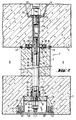
- FIG. 1 schematically shows a cross section through a tunnel vault 1, into which an intermediate ceiling 3 is suspended above the carriageway slab 2, parallel to it.
- the cavity between the tunnel vault 1 and false ceiling 3 is, as usual, through a vertical partition 4 in a ventilation and a ventilation channel 5, respectively. 6 divided.
- the false ceiling 3 is suspended from the tunnel vault 1 by means arranged in the intermediate wall 4 in the form of devices 7 according to the invention.
- the lateral connections 8 of the false ceiling 3 to the tunnel arch 1 are not taken into account in the context of the present invention, although they are important for the safety of the entire construction also play a significant role. The same also applies to the constructions of the tunnel vault 1 and the false ceiling 3 and the intermediate wall 4.
- the device 7 according to the invention for hanging the false ceiling 3 on the tunnel vault 1 essentially consists of three units, namely one upper anchoring 9 in the tunnel vault 1, a hanging unit 10 in the intermediate wall 4 and a lower anchoring 11 in the false ceiling 3.
- the structural details of these three units will be discussed in more detail below in connection with FIGS. 2 and 3.
- the upper anchoring 9 essentially consists of an advantageously cross-shaped anchoring bracket or pot 12 embedded in the tunnel vault concrete, to which a threaded sleeve 13 is connected, which extends into the region of the lower boundary of the concreted tunnel vault 1, where it joins with a lower end plate 14, advantageously by means of a screw 13 c, is connected.
- the end plate 14 is used, inter alia, in the manufacture of the tunnel arch 1 to nail the upper anchor 9 onto the formwork of the tunnel arch 1 by means of nail holes 15 provided for it.
- the end plate 14 serves as a stop for a pipe section 17 provided with a flange 16 and attachment by the pipe section 17 by means of set screws 18 which can be screwed into blind holes 20 provided with internal threads. Washers 19 are advantageously used for this purpose.
- connection of the anchoring bracket 12 with the threaded sleeve 13 is advantageously carried out by means of a threaded bolt 21 which, on the one hand, into an upper internal thread 13 a Threaded sleeve 13 is screwed and on the other hand, the anchoring bracket 12 is screwed from above by means of a nut 22 and a washer 23.
- a flexible hose 26 is advantageously inserted into these concrete parts, which extends from within the pipe section 17 down to a lower one, which is described in detail below Anchoring 11 connected pipe 27 extends.
- the lower anchor 11 which is embedded in the false ceiling 3 from below, essentially consists of a housing 28, advantageously with lateral reinforcing ribs 29, which serves as a receptacle for a ball joint plate 30.
- the latter is intended for interaction with a hemisphere 31 through which the hanging rod 24 passes and against which it is braced by means of a clamping nut 32 and advantageously a washer 33 and a lock nut 34.
- the inside diameter of the tube 27 is chosen larger on the one hand than that of the pipe section 17 and on the other hand, a seal 37 between the pipe 27 and hose 26 is provided.
- the housing 28 of the lower anchoring 11 is advantageously not axially symmetrical to the longitudinal axis of the hanging rod 24, but advantageously has an extension 38 on one side, which makes it easier to attach the wrench screwing the hanging rod 24 and tightening the clamping nut 32 and the lock nut 34 is used.
- a cover 40 is provided, which is advantageously provided in threaded blind holes 41 in the lateral reinforcing ribs 29 screw-in self-tapping screws 42 can be screwed tightly onto the housing 28 from below.
- the invention makes it possible to accommodate the suspension of the false ceiling 3 on the tunnel vault, completely isolated from the environment, essentially within concrete parts, without this making it impossible to check the load-bearing hanging rods 24. It is also essential that the invention makes it possible to individually pretension each hanging bar 24 and to load it with a predetermined load when the false ceiling 3 is suspended. As mentioned above, the invention also allows, to a certain extent, angular errors, which can arise, in particular, from an incorrect positioning of the upper anchor 9 in the tunnel vault 1, without compensating for the supporting parts.
- the device according to the invention is economical since even with varying Hanging height can be worked in a wide range with one and the same type of hanging bar.
- the person skilled in the art further recognizes that the ability to pretension the hanging rods 24 prevents the partition 3 from tearing off in the region of the tunnel arch 1 even in the event of fluctuations in load. As a result, it may be possible to dispense with the installation of a putty joint 43 at this point.
- the device according to the invention fulfills all the requirements placed on suspensions for false ceilings in tunnels and ensures that no load-bearing welds are present and that all parts of the false ceiling suspension that are critical in terms of safety can be checked at any time with relatively little effort and without destruction. It is economical and enables the individual parts to be largely standardized. It can also be used without problems with a false ceiling 3 designed as a vault, which increases the safety of the entire construction.
Abstract
Description
Die vorliegende Erfindung betrifft eine Vorrichtung für die Aufhängung von Zwischendecken, insbesondere aber nicht ausschliesslich von Zwischendecken in Tunneln, gemäss dem Oberbegriff des Patentanspruchs 1.The present invention relates to a device for suspending false ceilings, in particular but not exclusively from false ceilings in tunnels, according to the preamble of
Insbesondere beim Tunnelbau und hier vorwiegend im Autobahntunnelbau wird zwischen dem Tunnelgewölbe und der Tunnelfahrbahnplatte eine Zwischendecke eingehängt, um den durch den Verkehr verwendeten Tunnelquerschnitt von den durch die Be- und Entlüftungskanäle sowie die sonstigen Infrastrukturkanäle verwendeten Querschnitten abzutrennen. Die Sicherheitsanforderungen, die an die dafür verwendeten Aufhängungen gestellt werden, sind aus naheliegenden und verständlichen Gründen sehr hoch, muss doch sichergestellt werden, dass auch bei ausserordentlichen Vorkommnissen und Belastungen die Zwischendecke nicht auf die Fahrbahnplatte herunterstürzt und dadurch Tunnelbenützer gefährdet oder gar erschlagen werden. Neben der Gewährleistung der Sicherheit der Tunnelbenützer muss die Aufhängung auch eine dauerhafte Konstruktion aufweisen. Diese sowie weitere Anforderungen an Zwischendeckenaufhängungen werden durch die heute üblicherweise zum Einsatz gelangenden Aufhängungen in Form von Hängestangen und Ankern nur teilweise erfüllt.In tunnel construction in particular, and predominantly in motorway tunnel construction, an intermediate ceiling is hung between the tunnel vault and the tunnel carriageway slab in order to separate the tunnel cross-section used by traffic from the cross-sections used by the ventilation and ventilation ducts and the other infrastructure ducts. For obvious and understandable reasons, the safety requirements placed on the suspensions used are very high.However, it must be ensured that even in the event of extraordinary occurrences and loads, the false ceiling does not fall onto the road surface, thereby endangering or even slamming tunnel users. In addition to ensuring the safety of tunnel users, the suspension must also have a durable construction. These and other requirements for false ceiling suspensions are only partially met by the suspensions in the form of hanging rods and anchors that are commonly used today.
Der vorliegenden Erfindung liegt daher die Aufgabe zugrunde, eine Vorrichtung zur Aufhängung von Zwischendecken zu schaffen, die sämtliche gegenwärtigen und auch erwartete künftige gesetzliche Anforderungen erfüllen. In diesem Sinne soll die erfindungsgemässe Aufhängung auch kontrollier- und auswechselbar sein und keine tragenden Schweissstellen aufweisen. Weiter soll die Vorspannbarkeit der Hängestangen und die zerstörungsfreie Prüfung betreffend Korrosion mittels Potentialmessung gewährleistet sein.The present invention is therefore based on the object of providing a device for suspending false ceilings which meet all current and also expected future legal requirements. In this sense, the suspension according to the invention should also be controllable and replaceable and not load-bearing Show welds. Furthermore, the pretensionability of the hanging rods and the non-destructive testing regarding corrosion by means of potential measurement should be guaranteed.
Diese Aufgabe und weitere, sich aus der folgenden Beschreibung ergebende Bedingungen werden erfindungsgemäss durch eine Vorrichtung gemäss Patentanspruch 1 erfüllt.This object and further conditions resulting from the following description are achieved according to the invention by a device according to
Im Folgenden wird eine vorteilhafte Ausführungsvariante einer erfindungsgemässen Vorrichtung anhand der Zeichnung beschrieben. In letzterer zeigt
- Fig. 1 schematisch den Querschnitt durch ein Tunnelgewölbe, in das eine Zwischendecke eingehängt ist,
- Fig. 2 einen parziellen Längsschnitt durch eine erfindungsgemässe Vorrichtung in Form einer Aufhängung, und
- Fig. 3 einen parziellen Längsschnitt durch die untere Verankerung der Aufhängung in einer gegenüber der Schnittebene nach Fig. 2 um 90° geschwenkten Schnittebene.
- 1 schematically shows the cross section through a tunnel vault, in which an intermediate ceiling is suspended,
- Fig. 2 shows a partial longitudinal section through an inventive device in the form of a suspension, and
- 3 shows a partial longitudinal section through the lower anchoring of the suspension in a section plane pivoted by 90 ° with respect to the section plane according to FIG. 2.
Aus Fig. 1 erkennt man schematisch einen Querschnitt durch ein Tunnelgewölbe 1, in das oberhalb der Fahrbahnplatte 2, parallel dazu, eine Zwischendecke 3 eingehängt ist. Der zwischen Tunnelgewölbe 1 und Zwischendecke 3 liegende Hohlraum ist wie üblich durch eine senkrechte Zwischenwand 4 in einen Be- und einen Entlüftungskanal 5, resp. 6 aufgeteilt. Schematisch angedeutet ist, dass die Zwischendecke 3 durch in der Zwischenwand 4 angeordneten Mitteln in Form von erfindungsgemässen Vorrichtungen 7 am Tunnelgewölbe 1 aufgehängt ist. In diesem Zusammenhang ist zu erwähnen, dass die seitlichen Anschlüsse 8 der Zwischendecke 3 an das Tunnelgewölbe 1 im Rahmen der vorliegenden Erfindung unberücksichtigt bleiben, obwohl sie für die Sicherheit der gesamten Konstruktion ebenfalls eine nicht unwesentliche Rolle spielen. Entsprechendes gilt auch für die Konstruktionen des Tunnelgewölbes 1 und der Zwischendecke 3 sowie der Zwischenwand 4. Aus Fig. 1 erkennt man demgegenüber andeutungsweise, dass die erfindungsgemässe Vorrichtung 7 für das Aufhängen der Zwischendecke 3 am Tunnelgewölbe 1 im wesentlichen aus drei Einheiten besteht, nämlich einer oberen Verankerung 9 im Tunnelgewölbe 1, einer Hängeeinheit 10 in der Zwischenwand 4 und einer unteren Verankerung 11 in der Zwischendecke 3. Auf die konstruktiven Einzelheiten dieser drei Einheiten wird weiter unten im Zusammenhang mit den Fig. 2 und 3 näher eingegangen.1 schematically shows a cross section through a
In Fig. 2 ist eine oben im Tunnelgewölbe 1 und unten in der Zwischendecke 3 verankerte erfindungsgemässe Vorrichtung 7 mit verkürzter, in der Zwischenwand 4 verlaufender Hängeeinheit 10 dargestellt. Man erkennt, dass die obere Verankerung 9 im wesentlichen aus einem vorteilhafterweise kreuzförmigen im Tunnelgewölbebeton eingelassenen Verankerungsbügel oder -topf 12 besteht, mit dem eine Gewindehülse 13 verbunden ist, die bis in den Bereich der unteren Begrenzung des betonierten Tunnelgewölbes 1 reicht, wo sie mit einer unteren Endplatte 14, vorteilhafterweise mittels einer Verschraubung 13 c, verbunden ist. Die Endplatte 14 dient unter anderem bei der Herstellung des Tunnelgewölbes 1 dem Aufnageln der oberen Verankerung 9 auf die Schalung des Tunnelgewölbes 1 mittels dafür vorgesehenen Nagellöchern 15. Nach dem Ausschalen des Tunnengewölbes 1 dient die Endplatte 14 einem mit einem Flansch 16 versehenen Rohrstück 17 als Anschlag und Befestigung, indem das Rohrstück 17 mittels Stellschrauben 18, die in mit Innengewinden versehene Sacklöcher 20 eingeschraubt werden können. Vorteilhafterweise werden dazu Unterlagsscheiben 19 verwendet.2 shows a
Die Verbindung des Verankerungsbügels 12 mit der Gewindehülse 13 erfolgt vorteilhafterweise mittels eines Gewindebolzens 21, der einerseits in ein oberes Innengewinde 13 a der Gewindehülse 13 eingeschraubt ist und auf den andererseits von oben der Verankerungsbügel 12 mittels einer Mutter 22 und einer Unterlagsscheibe 23 aufgeschraubt ist.The connection of the
Der Fachmann erkennt, dass sämtliche Komponenten der oberen Verankerung 9 vor Umwelteinflüssen geschützt im Beton des Tunnelgewölbes 1 untergebracht sind und daher weitestgehend vor Korrosion geschützt sind.The person skilled in the art recognizes that all components of the
In ein unteres Innengewinde 13 b der Gewindehülse 13 ist eine sich im Rohrstück 17 erstreckende, ein vorteilhafterweise aufgerolltes oberes Aussengewinde 24 a aufweisende Hängestange 24 aus korrosionsfestem Stahl eingeschraubt, die durch die Zwischenwand 4 und die Zwischendecke 3 bis in die untere Verankerung 11 hinabreicht. Um der Hängestange 24 in der Zwischenwand 4 und in der Zwischendecke 3 einen vordefinierten Bewegungsspielraum 25 zu gewährleisten, ist vorteilhafterweise ein flexibler Schlauch 26 in diese Betonteile eingelegt, der sich von innerhalb des Rohrstückes 17 bis hinab in ein mit der weiter unten im Detail beschriebenen unteren Verankerung 11 verbundenes Rohr 27 erstreckt.In a lower internal thread 13 b of the threaded
Die untere Verankerung 11, die von unten her in der Zwischendecke 3 eingelassen ist, besteht im wesentlichen aus einem Gehäuse 28, vorteilhafterweise mit seitlichen Verstärkungsrippen 29, das als Aufnahme für eine Kugelgelenkplatte 30 dient. Letztere ist für das Zusammenwirken mit einer Halbkugel 31 vorgesehen, durch die die Hängestange 24 hindurchtritt und gegen die sie mittels einer Spannmutter 32 und vorteilhafterweise einer Unterlagsscheibe 33 sowie einer Gegenmutter 34 verspannt wird. Dazu bedarf es eines unteren, vorteilhafterweise ebenfalls aufgerollten Aussengewindes 24 b auf der Hängestange 24.The
Um die Hängestange 24 von unten her, durch die Zwischendecke 3 und die Zwischenwand 4 hindurch in die Gewindehülse 13 im Tunnelgewölbe 1 einschrauben zu können, weist diese an ihrem unteren Ende vorteilhafterweise eine Schlüsselanfräsung 35 auf.In order to be able to screw the hanging
Um für die Hängestange 24 und den flexiblen Schlauch 26 im Rohr 27 einen zusätzlichen Bewegungsspielraum 36 zu schaffen, ohne dass dadurch unerwünschte Verunreinigungen oder während dem Betonieren der Zwischendecke 3 flüssiger Beton in den Schlauch 26 eindringen können, wird einerseits der Innendurchmesser des Rohres 27 grösser gewählt als jener des Rohrstückes 17 und andererseits eine Abdichtung 37 zwischen Rohr 27 und Schlauch 26 vorgesehen.In order to create additional freedom of
Die Bewegungsspielräume 25 und 36 sowie das aus Kugelgelenkplatte 30 und Halbkugel 31 bestehende Kugelgelenk, an dem die Hängestange 24 unten festgelegt ist, ermöglichen es, ohne ungewünschte Verspannungen und Materialüberbeanspruchungen Winkelfehler von ca. 5° der Hängestangenmittelachse bezüglich der Senkrechten der Zwischendecke 3 zu kompensieren.The freedom of
Wie aus dem Vergleich von Fig. 3 mit Fig. 2 ersichtlich ist, ist das Gehäuse 28 der unteren Verankerung 11 vorteilhafterweise nicht achssymmetrisch zu der Längsachse der Hängestange 24 ausgebildet, sondern weist vorteilhafterweise einseitig eine Erweiterung 38 auf, die dem einfacheren Ansetzen der Schraubenschlüssel für das Einschrauben der Hängestange 24 sowie das Festziehen der Spannmutter 32 und der Gegenmutter 34 dient. Um ein ungewolltes Verdrehen der Hängestange 24, beispielsweise durch Erschütterungen der Zwischendecke 3 zu verhindern, ist es unter Umständen vorteilhaft, eine an der Kugelgelenkplatte 30 festlegbare Fixation 39 vorzusehen. Um das Eindringen von Schmutz und korrosionsfördernden Gasen in den das untere Ende der Hängestange 24 sowie die Spannmutter 32, die Gegenmutter 34 und das Kugelgelenk 30/31 enthaltenden Hohlraum des Gehäuses 28 zu verhindern, ist ein Deckel 40 vorgesehen, der vorteilhafterweise mittels in Gewindesacklöcher 41 in den seitlichen Verstärkungsrippen 29 einschraubbare Parkerschrauben 42 von unten dicht auf das Gehäuse 28 aufschraubbar ist.As can be seen from the comparison of FIG. 3 with FIG. 2, the
Der Fachmann erkennt, dass die Erfindung es ermöglicht, die Aufhängung der Zwischendecke 3 am Tunnelgewölbe völlig von der Umwelt isoliert im wesentlichen innerhalb von Betonteilen unterzubringen, ohne dass dadurch aber eine Kontrolle der tragenden Hängestangen 24 verunmöglicht würde. Wesentlich ist auch, dass die Erfindung es ermöglicht, jede Hängestange 24 individuell vorzuspannen und beim Aufhängen der Zwischendecke 3 mit einer vorbestimmten Last zu belasten. Wie weiter oben erwähnt, gestattet es die Erfindung auch, in gewissem Umfange Winkelfehler, die insbesondere durch ein nicht völlig korrektes Versetzen der oberen Verankerung 9 im Tunnelgewölbe 1 entstehen können, ohne Nachteie für die tragenden Teile auszugleichen.A person skilled in the art recognizes that the invention makes it possible to accommodate the suspension of the
Um ein einfaches und sicheres Kontrollieren der einzelnen Hängestangen 24 auch nach dem Einbau sicherzustellen, ist es einerseits notwendig, deren Belastungsgrenze so hoch anzusetzen, dass die beiden an die zu kontollierende und damit teilweise auszubauende Aufhängung angrenzenden Aufhängungen die durch den Ausbau einer Hängestange 24 entstehende Mehrbelastung gefahrlos aufnehmen können. Weiter ist es notwendig, vor dem Einschrauben der Hängestangen 24 und dem Vorspannen derselben mittels der Spann- und der Gegenmutter 32, resp. 34 die Gewindeteile 13 a, 13 b, 24 a, 24 b zu fetten, um ein Festklemmen derselben zu verhindern.In order to ensure that the
Da die Hängestangen 24 sowohl oben, in der Gewindehülse 13, als in gewissen Grenzen auch unten, in der unteren Verankerung 11 ohne Beeinträchtigung der Festigkeit der Verschraubungen und damit der Sicherheit der Aufhängung mehr oder weniger eingeschraubt werden können, ist die erfindungsgemässe Vorrichtung wirtschaftlich, da selbst bei variierender Hängehöhe in weiten Bereichen mit ein und demselben Hängestangentyp gearbeitet werden kann.Since the hanging
Der Fachmann erkennt weiter, dass durch die Möglichkeit, die Hängestangen 24 vorspannen zu können, ein Abreissen der Zwischenwand 3 im Bereich des Tunnelgewölbes 1 auch bei Belastungsschwankungen verhindert werden kann. Dadurch kann unter Umständen auf das Anbringen einer Kittfuge 43 an dieser Stelle verzichtet werden.The person skilled in the art further recognizes that the ability to pretension the hanging
Die erfindungsgemässe Vorrichtung erfüllt sämtliche an Aufhängungen für Zwischendecken in Tunnels gestellte Anforderungen und stellt sicher, dass keinerlei tragende Schweissungen vorhanden sind und alle in punto Sicherheit kritischen Teile der Zwischendeckenaufhängung jederzeit mit verhältnismässig kleinem Aufwand und zerstörungsfrei kontollierbar sind. Sie ist wirtschaftlich und ermöglicht weitestgehende Normierung der Einzelteile. Sie kann problemlos auch mit einer als Gewölbe ausgebildeten Zwischendecke 3 verwendet werden, was die Sicherheit der gesamten Konstruktion erhöht.The device according to the invention fulfills all the requirements placed on suspensions for false ceilings in tunnels and ensures that no load-bearing welds are present and that all parts of the false ceiling suspension that are critical in terms of safety can be checked at any time with relatively little effort and without destruction. It is economical and enables the individual parts to be largely standardized. It can also be used without problems with a
Die erfindungsgemässe Vorrichtung ermöglicht ein sinnvolles Vorgehen beim Bau von Tunneln, kann doch folgender Arbeitsablauf eingehalten werden:
- Massgenaues lotrechtes Versetzen der
oberen Verankerung 9 auf der Schalung desTunnelgewölbes 1. Nach dem Ausschalen muss lediglich ein vorteilhafterweise vorhandener Abdeckkleber von derEndplatte 14 entfernt werden. - Verschrauben des
Flansches 16 mit derEndplatte 14. - Schalen der
Zwischendecke 3. - Einschrauben der
Hängestange 24 in dieGewindehülse 13 deroberen Verankerung 9. - Überziehen des
flexiblen Schlauches 26 über dieHängestange 24 bis in das Rohrstück 17 hinein. - Montage des
Gehäuses 28 derunteren Verankerung 11 mit derKugelgelenkplatte 30 auf der Schalung derZwischendecke 3. - Zusammenbau des Kugelgelenkes und Richten und Fixieren der
Hängestange 24 in derunteren Verankerung 11. - Fixation und Abdichtung des
flexiblen Schlauches 26 imRohr 27 derunteren Verankerung 11. - Betonieren und Ausschalen der
Zwischendecke 3. - Schalen, armieren, betonieren und ausschalen der Zwischenwand 4.
Vorspannen der Hängestangen 24 mittels der Spannmuttern 32.Montage der Gegenmuttern 34 und derDeckel 40.
- Accurate vertical displacement of the
upper anchoring 9 on the formwork of thetunnel vault 1. After stripping, only an advantageously existing cover adhesive has to be removed from theend plate 14. - Screwing the
flange 16 to theend plate 14. - Shells of the
false ceiling 3. - Screwing the hanging
rod 24 into the threadedsleeve 13 of theupper anchor 9. - Pull the
flexible hose 26 over the hangingrod 24 into the pipe section 17. - Assembly of the
housing 28 of thelower anchor 11 with the balljoint plate 30 on the formwork of thefalse ceiling 3. - Assembling the ball joint and aligning and fixing the hanging
rod 24 in thelower anchorage 11. - Fixation and sealing of the
flexible hose 26 in thetube 27 of thelower anchor 11. - Concrete and formwork the
false ceiling 3. - Formwork, armoring, concreting and stripping the partition 4.
- Preloading the hanging
rods 24 by means of the clamping nuts 32. - Assemble the
lock nuts 34 and thecover 40.
Der Fachmann erkennt, dass die erfindungsgemässe Vorrichtung Vorteile gegenüber den bisherigen Vorrichtungen aufweist und sehr wirtschaftlich ist.The person skilled in the art recognizes that the device according to the invention has advantages over the previous devices and is very economical.
Claims (4)
- Device for the suspension of intermediate ceilings (3) in tunnels, including an upper anchorage (9) operatively associated with the tunnel roof (1) and a lower anchorage (11) operatively associated with the intermediate ceiling (3), as well as a suspension rod (24) which firmly connects these two mechanically, characterized in that the upper anchorage (9) includes an anchoring stirrup (12) embedded in the tunnel roof (1) and operatively associated with a threaded bush (13) and, by means of the latter, with an end plate (14) disposed on the inside of the tunnel roof (1), and in that the lower anchorage (11) includes a housing (28) which is embedded in the intermediate ceiling (3) and is accessible from the underside thereof, and which serves as a seat for a ball-and-socket joint (30/31), and in that a suspension rod (24) extends between the threaded bush (13) and the ball-and-socket joint (30/31) and, at one end, is screwed into the threaded bush (3) and, at the other end, is prestressed against the ball-and-socket joint (30/31) by means of a tensioning nut (32).
- Device according to Claim 1, characterized in that a pipe element (17) with a flange (16) is screwed onto the underside of the end plate (14), and in that the upper end of a flexible tube (26), which surrounds the suspension rod (24) between the pipe element (17) and a pipe (27) connected to the lower anchorage (11), projects into the tubular element (17).
- Device according to Claim 1, characterized in that the housing (28) comprises lateral reinforcing ribs (29) and can be closed in a leakproof manner by means of a cover (40).
- Device according to Claim 2, characterized in that there is a clearance (25) for movement between the tube (26) and the suspension rod (24).
Applications Claiming Priority (2)
| Application Number | Priority Date | Filing Date | Title |
|---|---|---|---|
| CH2265/90A CH681646A5 (en) | 1990-07-06 | 1990-07-06 | |
| CH2265/90 | 1990-07-06 |
Publications (2)
| Publication Number | Publication Date |
|---|---|
| EP0465413A1 EP0465413A1 (en) | 1992-01-08 |
| EP0465413B1 true EP0465413B1 (en) | 1995-03-15 |
Family
ID=4229729
Family Applications (1)
| Application Number | Title | Priority Date | Filing Date |
|---|---|---|---|
| EP91810478A Expired - Lifetime EP0465413B1 (en) | 1990-07-06 | 1991-06-20 | Device for the suspension of intermediate ceilings |
Country Status (5)
| Country | Link |
|---|---|
| EP (1) | EP0465413B1 (en) |
| AT (1) | ATE119969T1 (en) |
| CH (1) | CH681646A5 (en) |
| DE (1) | DE59104942D1 (en) |
| ES (1) | ES2071964T3 (en) |
Families Citing this family (4)
| Publication number | Priority date | Publication date | Assignee | Title |
|---|---|---|---|---|
| DE102004038595A1 (en) * | 2004-08-06 | 2006-03-16 | Ed. Züblin Ag | Tile-deck construction in tunnel construction and manufacturing method |
| KR101005605B1 (en) | 2010-06-07 | 2011-02-07 | 김태균 | Arch type wind duct slab and method for constructing wind duct of tunnel |
| WO2013044433A1 (en) * | 2011-09-26 | 2013-04-04 | Empire Technology Development Llc | Suspension mould |
| AT14430U1 (en) | 2014-07-08 | 2015-11-15 | Stu Stettin Hoch Und Tiefbau Gmbh | Device for the suspended attachment of a false ceiling of a tunnel |
Family Cites Families (1)
| Publication number | Priority date | Publication date | Assignee | Title |
|---|---|---|---|---|
| CH471287A (en) * | 1968-08-14 | 1969-04-15 | Beton Ag | Suspended ceiling and partition wall construction for tunnel ventilation |
-
1990
- 1990-07-06 CH CH2265/90A patent/CH681646A5/de not_active IP Right Cessation
-
1991
- 1991-06-20 ES ES91810478T patent/ES2071964T3/en not_active Expired - Lifetime
- 1991-06-20 AT AT91810478T patent/ATE119969T1/en not_active IP Right Cessation
- 1991-06-20 DE DE59104942T patent/DE59104942D1/en not_active Expired - Fee Related
- 1991-06-20 EP EP91810478A patent/EP0465413B1/en not_active Expired - Lifetime
Also Published As
| Publication number | Publication date |
|---|---|
| ATE119969T1 (en) | 1995-04-15 |
| EP0465413A1 (en) | 1992-01-08 |
| CH681646A5 (en) | 1993-04-30 |
| ES2071964T3 (en) | 1995-07-01 |
| DE59104942D1 (en) | 1995-04-20 |
Similar Documents
| Publication | Publication Date | Title |
|---|---|---|
| EP0311884A2 (en) | Manhole cover | |
| EP0545854B1 (en) | Shear mandrel connector device | |
| EP0465413B1 (en) | Device for the suspension of intermediate ceilings | |
| DE2519664A1 (en) | SPATIAL FRAMEWORK | |
| DE102008039965A1 (en) | Arrangement for fixing posts for protective walls | |
| EP0697489A1 (en) | Footfall sound damming supporting element | |
| EP2042657B1 (en) | Device for anchoring caps to the superstructure of buildings | |
| DE3201582A1 (en) | Device for securing people working on roofs, in particular flat roofs, against falling | |
| DE2908405A1 (en) | Scaffolding to building wall fixture - uses plug screwed threaded bar through hole in unit with splayed feet | |
| DE4423379C1 (en) | External balcony for existing building | |
| EP0253141B1 (en) | Prefabricated building element in particular staircase | |
| DE4215435A1 (en) | Noise damping connector for tread plate and stain check - has blind bore starting from check inside with conical widening towards base for bolt with expansion cone | |
| EP2507450B1 (en) | Züblin post anchoring system on engineering structures having a spherical washer/conical seat system | |
| AT286584B (en) | Support on vertical, load-bearing components | |
| EP1295839A1 (en) | Method and template to instal a landing door of an elevator | |
| DE3305128A1 (en) | Moment-proportioning, damping bearer/beam connection | |
| DE4116635A1 (en) | Fixing of cladding with rear ventilation space - using bracket bolted to base surface and projection which holds cladding off the surface | |
| DE8108672U1 (en) | RECOVERABLE SHUTTERING PART FOR THE ANCHORING AREA OF A TENSION LINK IN A CONCRETE COMPONENT | |
| DE202022001776U1 (en) | trapezoidal sheet metal fastening | |
| DE2648477A1 (en) | COMPLEX SHAFT EXPANSION FOR MINING | |
| DE2912131B1 (en) | garage | |
| EP0872604A1 (en) | Anchoring device for embedding in concrete and process for its manufacturing | |
| CH676370A5 (en) | Anchor member for balustrade - consists of tube with central threaded section internally and non-threaded sections on both sides of that section | |
| EP3660221A1 (en) | Building element and construction | |
| EP1236831A2 (en) | Method for constructing a wall, in particular a concrete wall on a bridge |
Legal Events
| Date | Code | Title | Description |
|---|---|---|---|
| PUAI | Public reference made under article 153(3) epc to a published international application that has entered the european phase |
Free format text: ORIGINAL CODE: 0009012 |
|
| 17P | Request for examination filed |
Effective date: 19910715 |
|
| AK | Designated contracting states |
Kind code of ref document: A1 Designated state(s): AT BE CH DE DK ES FR GB IT LI LU NL SE |
|
| 17Q | First examination report despatched |
Effective date: 19931022 |
|
| GRAA | (expected) grant |
Free format text: ORIGINAL CODE: 0009210 |
|
| AK | Designated contracting states |
Kind code of ref document: B1 Designated state(s): AT BE CH DE DK ES FR GB IT LI LU NL SE |
|
| PG25 | Lapsed in a contracting state [announced via postgrant information from national office to epo] |
Ref country code: NL Free format text: LAPSE BECAUSE OF NON-PAYMENT OF DUE FEES Effective date: 19950315 Ref country code: DK Effective date: 19950315 Ref country code: BE Effective date: 19950315 |
|
| REF | Corresponds to: |
Ref document number: 119969 Country of ref document: AT Date of ref document: 19950415 Kind code of ref document: T |
|
| ITF | It: translation for a ep patent filed |
Owner name: DR. ING. AUSSERER ANTON |
|
| REF | Corresponds to: |
Ref document number: 59104942 Country of ref document: DE Date of ref document: 19950420 |
|
| PG25 | Lapsed in a contracting state [announced via postgrant information from national office to epo] |
Ref country code: LU Free format text: LAPSE BECAUSE OF NON-PAYMENT OF DUE FEES Effective date: 19950630 |
|
| REG | Reference to a national code |
Ref country code: ES Ref legal event code: FG2A Ref document number: 2071964 Country of ref document: ES Kind code of ref document: T3 |
|
| ET | Fr: translation filed | ||
| GBT | Gb: translation of ep patent filed (gb section 77(6)(a)/1977) |
Effective date: 19950621 |
|
| NLV1 | Nl: lapsed or annulled due to failure to fulfill the requirements of art. 29p and 29m of the patents act | ||
| PLBE | No opposition filed within time limit |
Free format text: ORIGINAL CODE: 0009261 |
|
| STAA | Information on the status of an ep patent application or granted ep patent |
Free format text: STATUS: NO OPPOSITION FILED WITHIN TIME LIMIT |
|
| 26N | No opposition filed | ||
| PGFP | Annual fee paid to national office [announced via postgrant information from national office to epo] |
Ref country code: GB Payment date: 19990611 Year of fee payment: 9 |
|
| PGFP | Annual fee paid to national office [announced via postgrant information from national office to epo] |
Ref country code: SE Payment date: 19990616 Year of fee payment: 9 Ref country code: FR Payment date: 19990616 Year of fee payment: 9 |
|
| PGFP | Annual fee paid to national office [announced via postgrant information from national office to epo] |
Ref country code: ES Payment date: 19990625 Year of fee payment: 9 |
|
| PG25 | Lapsed in a contracting state [announced via postgrant information from national office to epo] |
Ref country code: GB Free format text: LAPSE BECAUSE OF NON-PAYMENT OF DUE FEES Effective date: 20000620 |
|
| PG25 | Lapsed in a contracting state [announced via postgrant information from national office to epo] |
Ref country code: SE Free format text: LAPSE BECAUSE OF NON-PAYMENT OF DUE FEES Effective date: 20000621 Ref country code: ES Free format text: THE PATENT HAS BEEN ANNULLED BY A DECISION OF A NATIONAL AUTHORITY Effective date: 20000621 |
|
| PGFP | Annual fee paid to national office [announced via postgrant information from national office to epo] |
Ref country code: DE Payment date: 20000626 Year of fee payment: 10 |
|
| PGFP | Annual fee paid to national office [announced via postgrant information from national office to epo] |
Ref country code: AT Payment date: 20000629 Year of fee payment: 10 |
|
| GBPC | Gb: european patent ceased through non-payment of renewal fee |
Effective date: 20000620 |
|
| EUG | Se: european patent has lapsed |
Ref document number: 91810478.7 |
|
| PG25 | Lapsed in a contracting state [announced via postgrant information from national office to epo] |
Ref country code: FR Free format text: LAPSE BECAUSE OF NON-PAYMENT OF DUE FEES Effective date: 20010228 |
|
| REG | Reference to a national code |
Ref country code: FR Ref legal event code: ST |
|
| PG25 | Lapsed in a contracting state [announced via postgrant information from national office to epo] |
Ref country code: AT Free format text: LAPSE BECAUSE OF NON-PAYMENT OF DUE FEES Effective date: 20010620 |
|
| REG | Reference to a national code |
Ref country code: ES Ref legal event code: FD2A Effective date: 20020204 |
|
| PG25 | Lapsed in a contracting state [announced via postgrant information from national office to epo] |
Ref country code: DE Free format text: LAPSE BECAUSE OF NON-PAYMENT OF DUE FEES Effective date: 20020403 |
|
| PGFP | Annual fee paid to national office [announced via postgrant information from national office to epo] |
Ref country code: CH Payment date: 20030516 Year of fee payment: 13 |
|
| PG25 | Lapsed in a contracting state [announced via postgrant information from national office to epo] |
Ref country code: LI Free format text: LAPSE BECAUSE OF NON-PAYMENT OF DUE FEES Effective date: 20040630 Ref country code: CH Free format text: LAPSE BECAUSE OF NON-PAYMENT OF DUE FEES Effective date: 20040630 |
|
| REG | Reference to a national code |
Ref country code: CH Ref legal event code: PL |
|
| PG25 | Lapsed in a contracting state [announced via postgrant information from national office to epo] |
Ref country code: IT Free format text: LAPSE BECAUSE OF NON-PAYMENT OF DUE FEES;WARNING: LAPSES OF ITALIAN PATENTS WITH EFFECTIVE DATE BEFORE 2007 MAY HAVE OCCURRED AT ANY TIME BEFORE 2007. THE CORRECT EFFECTIVE DATE MAY BE DIFFERENT FROM THE ONE RECORDED. Effective date: 20050620 |