EP0464383A2 - Plasma neutralisation cathode - Google Patents
Plasma neutralisation cathode Download PDFInfo
- Publication number
- EP0464383A2 EP0464383A2 EP91109114A EP91109114A EP0464383A2 EP 0464383 A2 EP0464383 A2 EP 0464383A2 EP 91109114 A EP91109114 A EP 91109114A EP 91109114 A EP91109114 A EP 91109114A EP 0464383 A2 EP0464383 A2 EP 0464383A2
- Authority
- EP
- European Patent Office
- Prior art keywords
- holder
- thermal emitter
- passage
- heater
- interior
- Prior art date
- Legal status (The legal status is an assumption and is not a legal conclusion. Google has not performed a legal analysis and makes no representation as to the accuracy of the status listed.)
- Granted
Links
Images
Classifications
-
- H—ELECTRICITY
- H01—ELECTRIC ELEMENTS
- H01J—ELECTRIC DISCHARGE TUBES OR DISCHARGE LAMPS
- H01J3/00—Details of electron-optical or ion-optical arrangements or of ion traps common to two or more basic types of discharge tubes or lamps
- H01J3/02—Electron guns
- H01J3/025—Electron guns using a discharge in a gas or a vapour as electron source
Abstract
Description
- This invention relates generally to glowing compensation cathodes, and more particularly to plasma compensation cathodes.
- There is known a glowing cathode (cf., Schats M.F."Heaterless Ignition of Inert Gas. Ion Thruster Hollow Cathodes" AJAA Paper, 1985) comprising a casing a cylindrical insert secured to the inner surface of the casing and functioning as thermal emitter, a heater secured at the outer side of the casing, and an orifice secured to end face of the casing and acting as the outlet hole of the cathode. This construction of cathode requires high power heaters to heat thermal emitter to a temperature ensuring thermoionic emission sufficient for maintaining a stable discharge.
- There is also known a plasma compensation cathode (cf., L.A. Artsimovich, et al "Razrabotka statsionarnogo plazmennogo dvigatelya i ego ispytanie na iskusstvennom sputnike Zemli Meteor", Kosmicheskie issledovania, 1974, tom XII, vyp. 3, pages 455 and 456, Fig. 5). This compensation cathode has a casing with an outlet hole at one wall thereof, the casing accommodating coaxially to its outlet hole a tubular holder receiving a thermal emitter with a central through passage. The compensation cathode also includes a heater embracing the tubular holder, and heat screens positioned between the holder and casing walls. Connected to the tubular holder is a pipe for feeding gas to the interior of the casing and to the passage of thermal emitter through its inlet portion. This pipe is secured in the casing through an insulator.
- During operation of the compensation cathode gas is conveyed through the tubular holder to the passage of the thermal emitter. Heated to a high temperature, the thermal emitter ensures emission of electrons sufficient for maintaining stable electric discharge between the inner surface of the thermal emitter and anode of the plasma source. After bringing the device to steady-state operation conditions the heater is deenergized, and the compensation cathode continues to operate automatically, whereby the preferred temperature level is ensured by the energy liberated in the catholyte layer approximating to the product of ionic current resulting from discharge by the potential drop at the cathode. However, in the course of operation the discharge can move from the passage of thermal emitter to the interior of tubular holder resulting in evaporation of the material of the holder and fouling of the passage with holder material to almost complete clogging. As a result, thermoemission surfaces tend to degrade, and thermoemission current tends to decrease thereby reducing the service life of the compensation cathode to only tens of hours. In addition, direct connection of the holder of thermal emitter to the gas feeding pipe leads to vigorous heat transfer from the emitter to outer structural parts, and consequently to move prominent catholyte potential drop ensuring the energy necessary for maintaining automatic operating conditions. More prominent catholyte potential drop also leads to reduced service life of the thermal emitter because of intensified ionic bombardment. In addition, tight contact of thermoemissive materials with the holder at high working temperatures is accompanied by active chemical interaction, such as penetration of boron followed by formation of metal borides, which in turn causes embrittlement and cracking of the holder material and thermal emitter to result in irreversible deformation of the holder. This disadvantageous effect is especially pronounced at starting operating conditions accompanied by the highest temperature levels, which limits the service life and reduces the total number of engagements of the compensation cathode. Also, the helical heater embracing the tubular holder is characterized by low rigidity to result in sagging and deformation of its coils resulting in possible contact of the coils with the holder or thermal screens and short-circuiting of the heater. This in turn leads to fewer engagements of the compensation cathode and reduced service life thereof. In addition, the working gas can contain negligeable qualntities of such admixtures as oxygen, water, or the like, tending to react at high working temperatures with the material of the thermal emitter and affecting the thermoemissive characteristics of the material. Extended operation for tens or hundreds of hours makes this disadvantageous effect even more prominent to reduce the service life of the compensation cathode.
- The present invention aims at providing a plasma compensation cathode which would be so constructed as to lock discharge zone in the passage of the thermal emitter, prevent chemical interaction of the thermal emitter with the material of the holder and with the thermal system maintaining automatically the poreferred temperature of the thermal emitter at minimised cathodic potential drop, and also to increase the rigidity of the heater and facilitate additional cleaning of gas from impurities.
- The aim of the invention is attained by that in a plasma compensation cathode comprising a casing accommodating coaxially with its outlet hole a hollow holder and thermal emitter having a central passage communicating with the interior of the holder, a heater embracing the holder, heat screens positioned between the heater and walls of the casing, and a pipe for feeding gas to the interior of the holder secured in a support insulator, according to the invention, the central passage of the thermal emitter is blind at the side of admission of gas and is communicated with the interior of the holder by way of a through passage made in the wall of the thermal emitter so that its axis intersects the axis of the central passage, and longitudinal grooves provided at the side surface of the thermal emitter at the location of inlet holes of the through passage, whereas the interior of the holder communicates with the gas feeding pipe through a sealed cavity defined by clearances between the coaxial heat screens successively interconnected by spacer rings and secured at the gas feeding pipe, underlying the holder in this cavity is a getter positioned between mechanical filters, the space between the inner surface of the holder and side surface of the thermal emitter accommodating a layer of material chemically inert at high working temperatures to the materials of the holder and thermal emitter, whereas the heater has a support ring located at its midportion and secured in an insulation sleeve separating the heater from the heat screens.
- The use in the proposed plasma compensation cathode of a thermal emitter with a special passage for feeding gas, a layer of chimically inert material, a system of coaxial heat screens, a support ring, an insulation sleeve, a getter, and mechanical filters makes it possible to substantially extend the service life and increase the total number of actuations of the cathode.
- The invention will now be described in greater detail with reference to a specific embodiment thereof taken in conjunction with the accompanying drawings, in which:
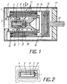
- Fig. 1 shows a general view of the proposed plasma compensation cathode; and
- Fig. 2 is a section taken along line 11 in Fig. 1
- A plasma compensation cathode comprises a casing 1 (Fig. 1) having an
inlet hole 2. The casing accommodates coaxially ahollow holder 3 and athermal emitter 4 with acentral passage 5. Theholder 3 is positioned insidecasing 1 coaxially with theoutlet hole 2 and embraced by aheater 6 fashioned as a spiral one end of which is secured to the casing and the other to theholder 3. Theheater 6 is provided with asupport ring 7 located at its midportion and functioning as an additional support point. - The
central passage 5 ofthermal emitter 4 is blind at the side of admission of gas, and is communicated with the interior of theholder 3 by way of a central passage 8 (Fig. 2) made in the wall of thethermal emitter 4, the axis of this passage extending perpendicularly to the axis of thecentral passage 5, andlongitudinal grooves 9 provided at the side surface of thethermal emitter 4 at location of the inlet holes of thethrough passage 8. Occupying the space between the inner surface of theholder 3 and side surface of thethermal emitter 4 is a layer 10 (Fig. 1) of material chemically inert at high temperatures to the materials of theholder 3 andthermal emitter 4. Positioned between theheater 6 and walls ofcasing 1 is a system of coaxial heat screens 11 connected successively throughspacer rings 12 and secured atpipe 13 for feeding gas to define a sealedcavity 14 wherethrough the interior of theholder 3 communicates with thegas feeding pipe 13. A space between theholder 3 andpipe 13 accommodates agetter 15 positioned betweenmechanical filters 16, whereas thepipe 13 is secured in asupport insulator 17. Theheater 6 is separated from the system of heat screens 11 by aninsulation sleeve 18 in which thesupport ring 7 is secured. - In operation of the proposed plasma compensation cathode the gas flows along the
pipe 13 through thegetter 15 andmechanical filters 16 to the interior of theholder 3, and then through thegrooves central passage 5 of thethermal emitter 4. Theheater 6 acts to heat thethermal emitter 4 to a temperature ensuring emission of electrons sufficient for sustaining a stable electric decharge between the inner surface of thethermal emitter 4 and anode (not shown) of a plasma source. After bringing the device to steady state operating conditions theheater 6 is deenergized and compensation cathode operates automatically, whereby the required temperature level of thethermal emitter 4 is ensured thanks to the energy resulting from the discharge. - When the
central passage 5 at the side of admission of gas is blind, the electric discharge inpassage 5 can be stabilized by changing the pressure of gas and dimensions of thepassage 5. This prevents fixation of discharge at the walls ofholder 3 resulting in fouling and clogging ofpassage 5 of thethermal emitter 4, which facilitates maintaining the initial thermal emission from the inner surface of thethermal emitter 4 and substantially increases the service life of the compensation cathode. Positioning between the inner surface ofholder 3 and side surface of thethermal emitter 4 oflayer 10 of material chemically inert to the material of holder andthermal emitter 4 obviates chemical interaction and diffusion of materials thereby making impossible irreversible deformation ofholder 3 and cracking ofholder 3 andthermal emitter 4. The accompanying advantage is substantially increased number of actuations and extended service life of the cathode. - The system of coaxial heat screens 11 defining with
gas feeding pipe 13 and holder 3 sealedcavity 14 makes it possible to substantially reduce the heat flow fromholder 3 of thethermal emitter 4 to outer parts of the cathode structure and, as a consequence, to reduce the potential drop at the cathode to the level of gas ionization potential and substantially extend the service life of the compensation cathode. - Provision of the
support ring 7 secured in theinsulation sleeve 18 allows to increase rigidity of the spiral ofheater 6, prevent short-circuiting of the spiral of heater 6 (viz., engagement of the spiral coils withholder 3 or screens 11) even at a substantial deformation of spiral coils due to multiple engagement thermocycles. This again enables to increase the number of actuations and extend the service life of the compensation cathode. - Provision of the proposed compensation cathode with
getter 15 positioned betweenmechanical filters 16 immediately at the location where the gas is admitted to the interior of theholder 3 affords extra fine chemical cleaning of gas from admixtures of oxygen, water, and the like, and ensures more stable thermoemission characteristics ofthermal emitter 4 resulting in an extended service life of the compensation cathode. - The invention can be used for neutralizing ion beams in accelerators with closed electron drift and extended acceleration zone, in accelerators with anodic layer and narow acceleration zone, in plasma-ion accelerators, and also for compensating space and surface discharges.
Claims (1)
- A plasma compensation cathode comprising a casing (1) accommodating coaxially with its outlet hole (2) a hollow holder (3) and thermal emitter (4) with a central passage (5) communicating with interior of the holder (3), heat screens (11) interposed between the heater (6) and walls of the casing (1), and a pipe (13) for feeding a gas to the interior of the holder (3) secured in a support insulator (17), CHARACTERIZED in that the central passage (5) of thermal emitter (4) is blind at the side of gas admission, and is communicated with the interior of the holder (3) by way of a through passage (8) made in the wall of the thermal emitter (4) so that its axis intersects the axis of the central passage (5), and longitudinal grooves (9) made at the side surface of the thermal emitter (4) at the location of inlet holes of the through passage (8), whereas the interior of the holder (3) communicates with gas feeding pipe (13) through a sealed cavity (14) defined by clearances between the coaxial heat screens (11) successively connected by spacer rings (12) and secured at the gas feeding pipe (13), the cavity (14) accommodating a getter (15) positioned under the holder (3) between mechanical filters (16), a space between the inner surface of the holder (3) and side surface of the thermal emitter (4) accommodating a layer (10) of material chemically inert at high temperatures to the material of the holder (3) and thermal emitter (4), whereas the heater (6) is provided with a support ring (7) at its midportion and secured in an insulation sleeve (18) separating the heater (6) from the thermal screens (11).
Applications Claiming Priority (2)
| Application Number | Priority Date | Filing Date | Title |
|---|---|---|---|
| SU904843045A RU2012946C1 (en) | 1990-06-26 | 1990-06-26 | Plasma cathode-compensator |
| SU4843045 | 1990-06-26 |
Publications (3)
| Publication Number | Publication Date |
|---|---|
| EP0464383A2 true EP0464383A2 (en) | 1992-01-08 |
| EP0464383A3 EP0464383A3 (en) | 1992-07-15 |
| EP0464383B1 EP0464383B1 (en) | 1994-09-21 |
Family
ID=21523026
Family Applications (1)
| Application Number | Title | Priority Date | Filing Date |
|---|---|---|---|
| EP91109114A Expired - Lifetime EP0464383B1 (en) | 1990-06-26 | 1991-06-04 | Plasma neutralisation cathode |
Country Status (5)
| Country | Link |
|---|---|
| EP (1) | EP0464383B1 (en) |
| JP (1) | JP2963903B2 (en) |
| AT (1) | ATE112096T1 (en) |
| DE (1) | DE69104142T2 (en) |
| RU (1) | RU2012946C1 (en) |
Cited By (5)
| Publication number | Priority date | Publication date | Assignee | Title |
|---|---|---|---|---|
| WO1999050878A2 (en) * | 1998-03-27 | 1999-10-07 | Forschungszentrum Karlsruhe Gmbh | Method for generating a pulsed electron beam and a trigger plasma source for carrying out said method |
| CN101390454B (en) * | 2006-02-23 | 2015-11-25 | 法国原子能委员会 | Transferred-arc plasma torch |
| CN113371233A (en) * | 2021-07-29 | 2021-09-10 | 哈尔滨工业大学 | Anode structure and cusp field thruster |
| CN114320801A (en) * | 2021-12-28 | 2022-04-12 | 哈尔滨工业大学 | Cold cathode capable of being started quickly |
| CN114458564A (en) * | 2022-04-12 | 2022-05-10 | 国科大杭州高等研究院 | Hall thruster ring type partial pressure gas path insulation structure |
Families Citing this family (9)
| Publication number | Priority date | Publication date | Assignee | Title |
|---|---|---|---|---|
| CN102355791A (en) * | 2011-09-28 | 2012-02-15 | 南京创能电力科技开发有限公司 | Device for insulation connecting between cathode and anode of plasma generator |
| RU2502238C2 (en) * | 2012-02-07 | 2013-12-20 | Федеральное государственное унитарное предприятие "Опытное конструкторское бюро "Факел" | Plasma cathode |
| CN105626410B (en) * | 2015-12-25 | 2018-08-03 | 上海空间推进研究所 | A kind of space electric thruster plume averager |
| RU2667155C1 (en) * | 2017-03-28 | 2018-09-17 | Федеральное государственное унитарное предприятие "Опытное конструкторское бюро "Факел" ФГУП "ОКБ "Факел" | Hollow cathode |
| RU2662795C1 (en) * | 2017-04-18 | 2018-07-31 | Федеральное государственное унитарное предприятие "Опытное конструкторское бюро "Факел" ФГУП "ОКБ "Факел" | Hollow cathode |
| RU2684633C2 (en) * | 2017-05-10 | 2019-04-11 | Федеральное государственное унитарное предприятие "Опытное конструкторское бюро "Факел" (ФГУП "ОКБ "Факел") | Cathode-compensator |
| RU2684309C1 (en) * | 2018-03-14 | 2019-04-08 | Федеральное государственное унитарное предприятие "Опытное конструкторское бюро "Факел" ФГУП "ОКБ "Факел" | Plasma hollow cathode |
| CN111720281B (en) * | 2020-06-24 | 2021-07-23 | 遨天科技(北京)有限公司 | Array coaxial type vacuum arc thruster device |
| CN115681054B (en) * | 2023-01-03 | 2023-05-09 | 国科大杭州高等研究院 | Self-maintaining Hall thruster |
Citations (2)
| Publication number | Priority date | Publication date | Assignee | Title |
|---|---|---|---|---|
| JPS58102440A (en) * | 1981-12-14 | 1983-06-18 | Toshiba Corp | Hollow-cathode electric-discharge device |
| JPS58169752A (en) * | 1982-03-30 | 1983-10-06 | Toshiba Corp | Hollow-cathode discharge device |
-
1990
- 1990-06-26 RU SU904843045A patent/RU2012946C1/en active
-
1991
- 1991-06-04 DE DE69104142T patent/DE69104142T2/en not_active Expired - Fee Related
- 1991-06-04 AT AT91109114T patent/ATE112096T1/en active
- 1991-06-04 EP EP91109114A patent/EP0464383B1/en not_active Expired - Lifetime
- 1991-06-25 JP JP3180134A patent/JP2963903B2/en not_active Expired - Lifetime
Patent Citations (2)
| Publication number | Priority date | Publication date | Assignee | Title |
|---|---|---|---|---|
| JPS58102440A (en) * | 1981-12-14 | 1983-06-18 | Toshiba Corp | Hollow-cathode electric-discharge device |
| JPS58169752A (en) * | 1982-03-30 | 1983-10-06 | Toshiba Corp | Hollow-cathode discharge device |
Non-Patent Citations (3)
| Title |
|---|
| PATENT ABSTRACTS OF JAPAN vol. 7, no. 204 (E-197)(1349) 9 September 1983 & JP-A-58 102 440 ( TOKYO SHIBAURA DENKI K K ) 18 June 1983 * |
| PATENT ABSTRACTS OF JAPAN vol. 7, no. 292 (E-219)(1437) 27 December 1983 & JP-58 169 752 ( TOKYO SHIBAURA DENKI K K ) 6 October 1983 * |
| PROCEEDINGS OF THE 8TH SYMPOSIUM ON ENGENEERING PROBLEMS OF FUSION RESEARCH vol. 2, 1979, NEW YORK pages 1038 - 1043; D.E. SCHECTER: 'HOLLOW CATHODE FOR POSITIVE ION SOURCES' * |
Cited By (7)
| Publication number | Priority date | Publication date | Assignee | Title |
|---|---|---|---|---|
| WO1999050878A2 (en) * | 1998-03-27 | 1999-10-07 | Forschungszentrum Karlsruhe Gmbh | Method for generating a pulsed electron beam and a trigger plasma source for carrying out said method |
| WO1999050878A3 (en) * | 1998-03-27 | 2001-12-20 | Karlsruhe Forschzent | Method for generating a pulsed electron beam and a trigger plasma source for carrying out said method |
| CN101390454B (en) * | 2006-02-23 | 2015-11-25 | 法国原子能委员会 | Transferred-arc plasma torch |
| CN113371233A (en) * | 2021-07-29 | 2021-09-10 | 哈尔滨工业大学 | Anode structure and cusp field thruster |
| CN113371233B (en) * | 2021-07-29 | 2022-08-30 | 哈尔滨工业大学 | Anode structure and cusp field thruster |
| CN114320801A (en) * | 2021-12-28 | 2022-04-12 | 哈尔滨工业大学 | Cold cathode capable of being started quickly |
| CN114458564A (en) * | 2022-04-12 | 2022-05-10 | 国科大杭州高等研究院 | Hall thruster ring type partial pressure gas path insulation structure |
Also Published As
| Publication number | Publication date |
|---|---|
| JP2963903B2 (en) | 1999-10-18 |
| DE69104142T2 (en) | 1995-01-19 |
| RU2012946C1 (en) | 1994-05-15 |
| EP0464383B1 (en) | 1994-09-21 |
| JPH04299000A (en) | 1992-10-22 |
| EP0464383A3 (en) | 1992-07-15 |
| ATE112096T1 (en) | 1994-10-15 |
| DE69104142D1 (en) | 1994-10-27 |
Similar Documents
| Publication | Publication Date | Title |
|---|---|---|
| EP0464383B1 (en) | Plasma neutralisation cathode | |
| US5359254A (en) | Plasma compensation cathode | |
| US5241243A (en) | Device with unheated hollow cathode for the dynamic generation of plasma | |
| US8143788B2 (en) | Compact high current rare-earth emitter hollow cathode for hall effect thrusters | |
| US4301391A (en) | Dual discharge plasma device | |
| CN111120234B (en) | Graphite high-temperature cathode device for electric thruster | |
| US4157471A (en) | High temperature ion source for an on-line isotope separator | |
| US6870321B2 (en) | High-frequency electron source | |
| US3311769A (en) | Gaseous discharge lamp with internally cooled eletrodes | |
| FI68928C (en) | CATHODIC FOER LYSROER | |
| US3683295A (en) | Gas laser discharge tube | |
| US4954751A (en) | Radio frequency hollow cathode | |
| US3304456A (en) | Slot cathode | |
| CN100482030C (en) | Extreme UV and soft x ray generator | |
| RU2662795C1 (en) | Hollow cathode | |
| US2053002A (en) | Vacuum vessel | |
| US3100272A (en) | Low pressure mercury plasma discharge tube | |
| CN218160268U (en) | Tantalum tube insulating part structure of hollow cathode ion source neutralizer | |
| GB2194673A (en) | Apparatus for forming an electron beam sheet | |
| US20240062995A1 (en) | Hollow cathode system for generating a plasma and method for operating such a hollow cathode system | |
| US11937361B1 (en) | Annular hollow cathode | |
| US20240014014A1 (en) | High current heaterless hollow cathode | |
| RU2816693C1 (en) | Plasma source of electrons with system for automatic ignition of glow discharge in hollow cathode, operating in medium vacuum | |
| RU2139590C1 (en) | Cathode unit | |
| JPH10158823A (en) | Ion plating device and formation of thin film by this device |
Legal Events
| Date | Code | Title | Description |
|---|---|---|---|
| PUAI | Public reference made under article 153(3) epc to a published international application that has entered the european phase |
Free format text: ORIGINAL CODE: 0009012 |
|
| AK | Designated contracting states |
Kind code of ref document: A2 Designated state(s): AT CH DE FR GB IT LI NL |
|
| PUAL | Search report despatched |
Free format text: ORIGINAL CODE: 0009013 |
|
| AK | Designated contracting states |
Kind code of ref document: A3 Designated state(s): AT CH DE FR GB IT LI NL |
|
| 17P | Request for examination filed |
Effective date: 19920826 |
|
| 17Q | First examination report despatched |
Effective date: 19940126 |
|
| GRAA | (expected) grant |
Free format text: ORIGINAL CODE: 0009210 |
|
| AK | Designated contracting states |
Kind code of ref document: B1 Designated state(s): AT CH DE FR GB IT LI NL |
|
| REF | Corresponds to: |
Ref document number: 112096 Country of ref document: AT Date of ref document: 19941015 Kind code of ref document: T |
|
| ITF | It: translation for a ep patent filed |
Owner name: BARZANO' E ZANARDO MILANO S.P.A. |
|
| REF | Corresponds to: |
Ref document number: 69104142 Country of ref document: DE Date of ref document: 19941027 |
|
| ET | Fr: translation filed | ||
| PG25 | Lapsed in a contracting state [announced via postgrant information from national office to epo] |
Ref country code: GB Effective date: 19950604 Ref country code: AT Effective date: 19950604 |
|
| PG25 | Lapsed in a contracting state [announced via postgrant information from national office to epo] |
Ref country code: LI Effective date: 19950630 Ref country code: CH Effective date: 19950630 |
|
| PLBE | No opposition filed within time limit |
Free format text: ORIGINAL CODE: 0009261 |
|
| STAA | Information on the status of an ep patent application or granted ep patent |
Free format text: STATUS: NO OPPOSITION FILED WITHIN TIME LIMIT |
|
| 26N | No opposition filed | ||
| PG25 | Lapsed in a contracting state [announced via postgrant information from national office to epo] |
Ref country code: NL Effective date: 19960101 |
|
| GBPC | Gb: european patent ceased through non-payment of renewal fee |
Effective date: 19950604 |
|
| PG25 | Lapsed in a contracting state [announced via postgrant information from national office to epo] |
Ref country code: FR Effective date: 19960229 |
|
| REG | Reference to a national code |
Ref country code: CH Ref legal event code: PL |
|
| NLV4 | Nl: lapsed or anulled due to non-payment of the annual fee |
Effective date: 19960101 |
|
| PG25 | Lapsed in a contracting state [announced via postgrant information from national office to epo] |
Ref country code: DE Effective date: 19960301 |
|
| REG | Reference to a national code |
Ref country code: FR Ref legal event code: ST |
|
| PG25 | Lapsed in a contracting state [announced via postgrant information from national office to epo] |
Ref country code: IT Free format text: LAPSE BECAUSE OF NON-PAYMENT OF DUE FEES;WARNING: LAPSES OF ITALIAN PATENTS WITH EFFECTIVE DATE BEFORE 2007 MAY HAVE OCCURRED AT ANY TIME BEFORE 2007. THE CORRECT EFFECTIVE DATE MAY BE DIFFERENT FROM THE ONE RECORDED. Effective date: 20050604 |